
Induction Heater - Series Resonant - uC/PLL Tuning [ReactorForge]
Josh Campbell, Tue Jun 19 2012, 03:51AM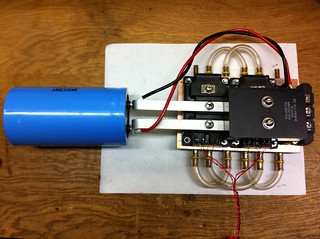
************************************************** **********
Github Repository: https://github.com/ThingEngineer/ReactorForge
************************************************** **********
Photos: Flickr - Induction Heater (updated as I progress)
Goal: Replace dirty coal forge and heat producing propane forge in my brothers blacksmith shop for work on smaller items.
Primary Requirements:
- Heat .5 inch square carbon steel to 2200-2400 °F DONE
- Easy and safe to use by non technical users Easy DONE, working on safe
- Draw under 30 Amps at 120V Update: 60A at 240V DONE
- Water cooled work coil DONE
- Water or air cooled electronics DONE
- Thermal readout of water temperature, power supply, and inverter DONE
- Mains current usage readout DONE
- Auto shutdown and warning for an over temperature condition DONE
- Operate in the 30-100KHz range DONE
- Fully automatic - No user tuning required DONE
- Working coil changeable by user without opening case DONE
- Foot switch operation DONE
Secondary Requirements:
- Heat .5 inch square carbon steel to 2600–2800 °F DONE
- Thermal display (LED or LCD) DONE
- Built in power control for operating at less than 100% powerDONE
- Multiple resonant tank frequencies via capacitor or working coil inductor changes without system recalibration DONE
- EMI filtering DONE
- Unity power factor DONE (.97 to .99)
Type: uP/PLL tuned inverter coupled to a series resonant tank via a toroidal coupling transformer, .5-1.5 uH work coil
Resources:
- All the other great IHs on this site of course!
************************************************** **********
************************************************** **********
Progress: (See Flickr gallery for full-size photos, and more photos not shown here.)
- 12/29/2017
Another video, this one goes over the basic functionality of the machine. Not how to use it but more how it works on a high-level. I'll be making videos of each component/system and how they specifically work individually, this is more a walkthrough of how they all work together. (And don't worry, I'll get a microphone before making those videos.)
Have a great weekend everyone!
Here is the link if the embeded video doesn't work.
https://youtu.be/q-JiucZY7mM
- 12/29/2017 Here is a video update from today.

I ran into an issue with the IGBT drivers. And rather than trying to patch the prototype boards up AGAIN I think it's time to get some real boards made for the ReactorForge.
- 12/16/2017
Wow, jump forward in time again and here we are. I have been busy over the years but I have never given up or complete stopped work on the ReactorForge. I am making an active effort to continue this project now.
I've got it hooked up to a decent chiller now. No more pond pump and the 5-gallon bucket with a small computer fan radiator. Although that worked quite well.

I also set the whole thing up on a rolling metal cart from Sam's Club. This was perfect, lots of room on the bottom for the chiller, a small area for spare coils and a shallow top for the induction heater to sit.
I'm now working on the new firmware. If you follow the GitHub (click watch) you'll see the progress.
Since the scope of this project has gotten quite large I needed a bit more room than one forum thread so I have also been posting updates on the blog and on Patreon. But I will continue to update this thread and be active on here as well. Thank you all for your input and help over the years!
- 6/13/2014
It's been a while since my last update here but I've been busy with this project and my day job. Since the last update, my brother has quit his day job, built a big new shop and is now full time making tools using an updated induction heater model as his sole heat source (no coal or gas forge).
In an effort to give back to the open source community I have organized the older project files into a repository on GitHub that I am making publicly available under the project name ReactorForge. This repository includes all schematics and code for my first 2 induction heaters (the second of which has been in operation full time for over a year). Over the coming weeks I will be organizing and releasing the information for the new version seen in the video below. This will be the last update to this thread as it has been focused on the older model. The newest prototype is much different and I will be starting a new thread to cover it.
The video below is of the mark III beta prototype (code name: CriticalMass) in operation.
- 2/15/2012
My brothers company he started, Argyll Hammer is doing well on eBay and he's starting to get customer orders now. He just posted this one today on his Facebook page:
"Big order, 40 pairs of tongs going to the guys at Trackers Earth, a wilderness survival/outdoor skills school in Oregon. They will be doing some blacksmithing classes soon now too and needed tools."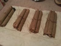
The pressure is on to get the next version up and running. Just working on the case and refining the coupling transformer.
- 01/2013:
I updated this thread so that the newest updates are on top and the old ones are on bottom since it was getting so long. I'll remember to do that in the future since it was a pain inverting the list items.
I've added a cooling solution to the IH to eliminate the need for running hoses to and from it before use.
I also added a small high CFM fan with a push button switch powered from the 12V cooling fan supply to pull away fumes when heating a work piece. This came as a request from my brother who was surprised this was not an add on feature for commercial units.
Pump 1/2HP 650GPH
Radiator for 4 x 120mm
High RPM 12V Fan 120mm x 4
12V Power Supply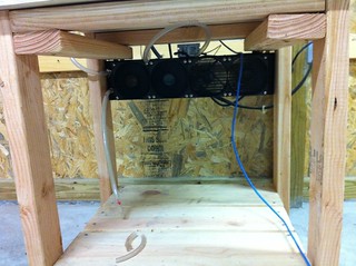
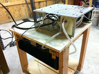
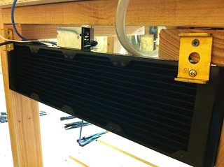
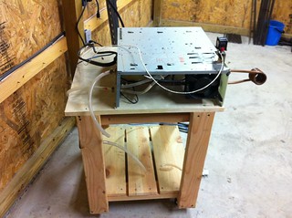
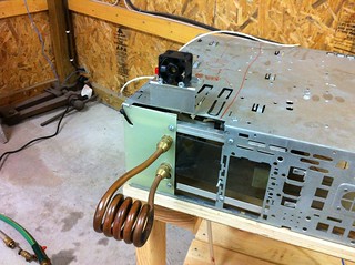
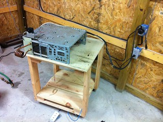
What's next? Well not much for this unit. I've been working on the next one which is an LCLR tank topology vs this series resonant version. The entire unit is more robust and much simpler. I've eliminated the PLL drive and am driving each of 4 individual gate drivers with a high frequency PWM (64MHz base F) power stage controller. This has eliminated the touch analog circuitry, and most important allowed me to phase shift the full-bridge for perfectly smooth power control from 0 to 100%.
I'll be compiling that project in it's own topic most likely since it is vastly different from this one. I'll also circle back and update the schematics and code for this one. The field testing and heavy use my brother has put on the unit has reviled much and yielded beneficial changes.
On another note, my brother sold his Habañero Chile Grande -
Not because it didn't work as intended but because it was more expensive and vastly less convenient to use than the IH. He also went part time on his day job and is now making more selling custom tools than he is in his career position. So the pressure is on to get a more reliable, higher power unit going! Not to mention a backup.
- 8/18/2012:
My brother made a video of his shop progress and did a big portion of it on the IH, it was cool seeing it used by someone besides myself when I was not there to baby it which was really the biggest goal.
When he is talking he is addressing some online blacksmith community. A quick warning, he is a big dork which is not the same as us nerds and geeks. :)
update: I think he deleted the video.
Work in progress UPDATE: COMPLETE:
A few of the items I'm working on right now:- The next tank setup which will eliminate case heating by reducing inductance and raise tank efficiency.
- A new control board with lots of upgrades including a micro-controller that will do the phase locking (on its own, no FPGA, working on a breadboard now with a small LV test tank, just needs some more tweaking). This is big not because there is an issue with the PLL, that thing works like a champ. But because it will allow me to have a tunable range with no center frequency, basically a PLL that can set it's own tunable range each time it runs allowing the user to switch coils out without retuning the PLL circuit. I know I could accomplish this to some degree using a varactor (C1) and two digitally set potentiometers (R1,R2) on the PLL but that's adding more failure points to an already touchy circuit in my opinion.
- I'm also redesigning the IGBT driver to be more like a commercial driver with isolated DC/DC converters for each transistor, fault sensing and protection to detect over-current and short-circuit conditions, adjustable blocking time, desaturation protection and better common mode rejection... to name a few.
- 9/16/2012: So exciting day today, finally got the IH set up in my brother shop for some real life tests and heavy use. After using it for only a few minutes I think he was ready to git rid of his $1500 propane forge he just bought.
There was a lot more I wanted to work on such as better current limiting, current readout on the LCD, program timed cycles, temperature sensing and safety cutoffs, etc. Although the unit can run at a 20KW (.99PF) at 100% duty cycle indefinitely with no over heating as long as the water is running even with no work piece in the coil. Much more over 20KW and the coupling coil heats up above 130F so that will be the first thing that gets upgraded. I'm going to let him keep this one and build a new one with a new board and better tank setup and see how far I can go. He would like to be able to melt about 5-10lbs of material for making his own steel, seems easily do able.
Anyway here are a few pics and videos, nothing really technical just the results of a semi-permanent setup in the shop. I left the case off to allow some tweaking if needed and because there is a bit of inductive heating in the case where the tank is close to the metal, a cleaner tank setup will probably solve that. Copper stock on order!
Messing with a 1/2 bar at 10-20KW (10 cold, 18-20 hot)
Pulling apart a 1/2" bar with an induction heater at about 12 KW
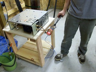
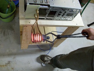
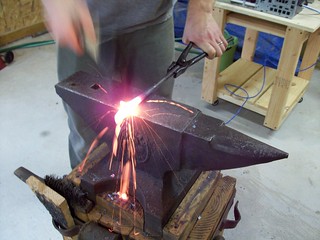
More in the Flickr album of course...
9-12-2011: Here is the current schematic for the control board and a few photos of the first prototype board, good bye noisy breadboard!
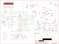
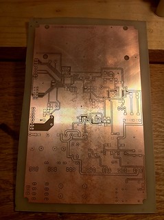
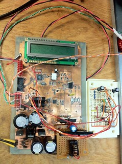
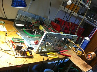
The small breadboard on the side was for testing an active filter/amplifier for mains current sensing (which is a pure sine wave with Fo embedded in it) that is currently using a ratiometric hall effect sensor: ACS756SCA-100B. There were a few other tweaks and additions I made after the board was fabricated as with most prototypes, but the schematic is updated.
Also it now supports small controlled fusion reactions. ;)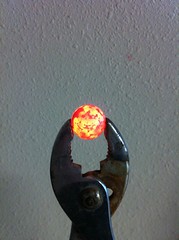
- 8/24/2012: Ok it's been a while since my last update, these things take time to create and well time is money. I received the hall effect sensors (Allegro's ACS758ECB-200B-PSS-T) and have those hooked up to monitor mains current so I can implement current limiting and power factor correction. These are very easy to use, the output is ratiometric to Vcc so it remains accurate in a noisy environment and with temperature fluctuations.
The main reason for current monitoring was to be able to implement some form of current limiting. At the moment I am using a simple zero point detector circuit to signal to the uController the beginning of an AC cycle. A time delay is then imposed before reading the current with an ADC channel to ensure that the reading is taken at the peak of each cycle.
2mS Scale
Top trace: Top half of the 20V-peak AC on the low voltage power supply
Bottom trace: 5V squared representation of the mains AC inverted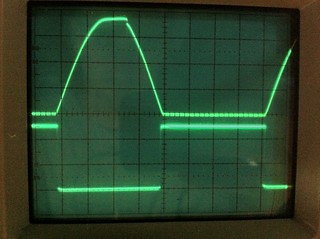
So using falling edge detection to fire an interupt in the uController we can now measure the current at any phase angle on the positive current slop.
1mS Scale
Top trace: Top half of the 20V-peak AC on the low voltage power supply
Bottom trace: 5V test pulse generated 4mS after the beginning of the positive going AC slope putting the test pulse roughly at the peak of the half cycle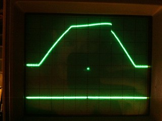
Shown below is the 240VAC waveform along with the mains current waveform. Since we are using a rectifier and a filter capacitor we have this horrible non-linier current wave form. To measure the peak current we need to sample it at exactly 2mS into the positive half cycle. We can not simply cut off the bottom of the current waveform and smooth it with a low pass filter since the waveform is non-linier. Doing so would give us an average current reading, but I am interested in the peak current. This is where some reading up on Power Factor would be good if you do not already understand the benefits of having a unity power factor.
Power factor on Wikipedia
Power Factor Basics <-- very good one
2mS Scale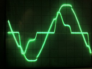
There was a problem with measuring the current at a set phase angle, depending on the load the current waveform can shift or change shape entirely as seen below.
2uS Scale
120VAC waveform along with the mains current waveform. This is a better power factor than running on 240V at higher power levels but still below .80.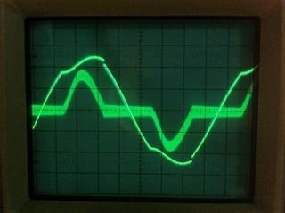
So I need to measure the current at any point from 0-90 or 0-4mS from the positive slop trigger point. I decided to run the ADC continuously after triggered by the falling edge of the inverted square AC waveform, keeping track of two values. 1: the highest current value read since the beginning of this phase and 2: the average current value since the beginning of this phase. The ADC keeps running until the average level begins to drop, a 5 amp drop was a good point to avoid prematurely stoping the ADC due to fluctuation. This means the zero point detector is no longer needed for current reading, but I still have something else in mind that will require it later... active power factor correction.
Power factor is a big deal when you are drawing a lot of current. Say running at 240VAC your peak current is 100A but your current wave form is non-linear, you have a lot of wasted power or KVAR. If your power factor is .75 then then your true power or KW is only 18,000, the KVAR is 6,000, and the total KVA is 24,000. Your machine is making use of 18,000 watts of power or 75A but your breaker, rectifier, and filter cap all need to be able to handle 24,000 watts or 100A. If you could bring your power factor closer to unity or 1 then your reactive power (KVAR) to true power (KW) would be zero and the current used in the system would equal the current supplied to the system. So no energy would be wasted as reactive power.
There are many ways to go about correcting power factor depending on if you have an inductive, capacitive, or non-linear voltage to current phase relationship. The method I had chosen, although it would require a fairly large inductor was a buck-boost type which to put it simply uses a switch to short the rectifier output across an inductor. The inductor holds a charge that is then released back into the filter capacitor through a diode. The switching rate is varied to force the capacitor to draw charging current in phase with the AC mains. Not a terribly complex idea and not complex to implement. But it does require another switch either MOSFET or IGBT since the switching rate is still fairly low which means another driver. And it requires a large inductor to store energy and a diode to direct the flow of that energy. It will also require uProcessor time to read the current waveform and adjust the pulse rate to correct as needed, or a stand alone buck-boost power factor correction chip which will require another handful of passive components. In short I'm trying to keep this project simple and cost effective but still with incorporate some valuable features like power factor correction.
This lead me to start at the root of the problem (which is why it has been a while since my last update). What causes bad power factors. A lightbulb which presents a purely resistive load on the AC mains has a perfect power factor of .98 to 1. (Some stray inductance here and there, and probably a very small amount in the filament coil.) But nearly perfect by any measure. So what is causing my big amp sucking DC power supply to have such a crap current waveform. The rectifier itself doesn't draw any current or affect current draw of the load, hook one up to AC and you get 120Hz out. Hook a light bulb up to that and you still get a power factor of 1.
AC Mains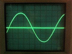
Rectifier output (Inverter input) No Load / Load
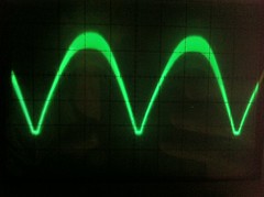
Hook a filter capacitor up to that same circuit and bam, the power factor drops to about .70. This is because the capacitor does not re-charge in phase with the voltage. Rather the current begins to rise early in the phase and peaks just before the peak of the voltage so the current leads the voltage. Any capacitive reactance causes current to lead voltage. We could counter act that capacitive reactance with inductive reactance, similar to what is happening in the tank circuit at resonance. But we have the same problem here as we did trying to read the current at the peak of the waveform, depending on the load that the IH is drawing the effect of capacitive reactance varies because there are other factors involved besides a simple XL/XC circuit, so we would need to vary the inductance. Again requiring the need to read the complex waveform and adjust.
Let's go back to the light bulb hooked up to the AC mains through a rectifier with no filter capacitor. Why can't I do that with the induction heater? Rather than a feeding a fixed DC voltage of 340V (240 x √2) to the IGBTs and getting a consistent square wave output of pulsed 340V we feed 120Hz 340V peak into the IGBT inverter and the output is a 120Hz envelope containing the resonant high frequency component. Well I say I can do that. There can be issues with under voltage IGBT's turning on from an off state but since we are pulsing them at a frequency much higher than the frequency of the input voltage this effect is non-existant or does not affect IH operation at least.
Power Factor reading on a Kill-a-Watt meter (While running on 120V about 10A)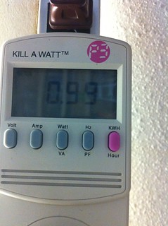
240VAC mains input and current waveforms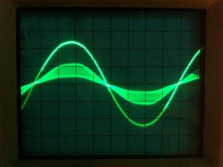
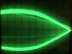
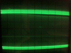
Same as above but zoomed in on the high frequency resonant component of the current waveform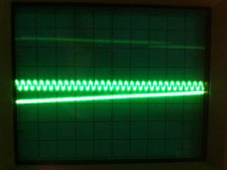
Inverter drive Fo and mains current waveform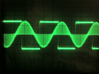
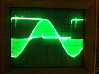
Inverter output showing the resonant component Fo inside of the 120Hz envelope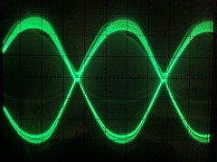
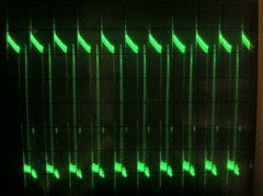
Another feature I added was soft starting and stopping of the inverter Fo by ramping the PWM output feeding the VCO from 15V (Max VCO Fo) down until a resonant lock is achieved, and when the stoping the IH the VCO is ramped up from it's current setting back to VCO max be for disabling the PLL VCO using pin 5 of the PLL. This gives a nice smooth start and stop of the inverter with no bucking or large in-rush current.
So far I have not been able to find any negative side effects in running the inverter like this, only one big positive. Which is 25% less current draw while still maintaining the same output power both by measurement and by results.
1/2 Bar white hot and sparking in 10 seconds from cold. Melted in half at about 12 seconds.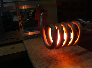
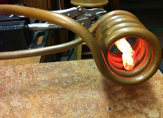
In this video I pulse the IH on and off to keep the metal from just melting and falling off but keep it hot enough to burn it away. I am going to add a code to allow the user to change the maximum current so pulsing to do this type of heating will not be necessary.
Melting 1/2 carbon steel
Time for some fun:
Penny Fire:
Zinc has a fairly low ignition temperature, seen here is the zinc oxide left behind from a penny fire! I had a vacuum ventilating to outdoors for this. I would have taken a picture of the fire but I was to busy making sure it was contained. It was a brilliant white (similar to burning magnesium) with a ting of green. Out of the fire spewed long strands of smokey blue zinc oxide.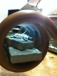
Another way to use the work coil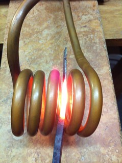
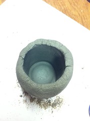
Quickie furnace cement crucible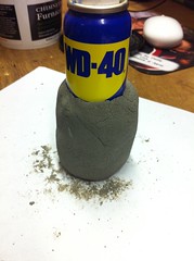
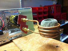
Molten zinc in a crucible and the effect of the magnetic field on the zinc.
Molten Al, Cu, Zn alloy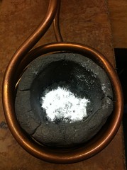
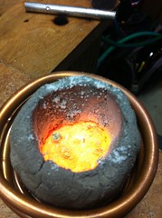
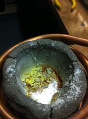
Cooled Al,Cu,Zn alloy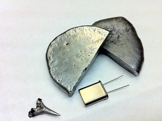
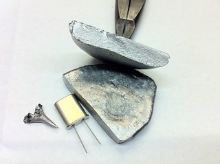
Alloy: 75% Al - 20% Cu - 5% Zn : This ended up being a very interesting alloy, with a dark sheen and heavy feel, very brital even though it was cooled slowly and has a beautiful crystalline structure.
Alloys of Al Cu and Zn are very common and among some of the hardest and lightest known to man. With a little precipitation hardening this one would be much less brittle but it has much more copper than most alloys of this type to be useful for much.
- 8/9/2012: I've migrated away from the MOSFETs to IGBT's using a simple driver setup, TC4421A/22A's driving a P0585NL gate transformer which is controlling the gates of 4 x 30W discreet MOSFETs which are in turn driving a custom wound 1:1:1:1:1 gate transformer that can handle about 30 watts to drive the IGBTs directly. I chose to go ahead and do this before working on the current limiting for two reasons. One because IGBT's will be used in the final design so it has to happen anyway and two because I'm waiting on some single IGBT blocks for the current limiting circuit. I'm not going to use SCR's like originally planned. I'm either going to detune the tank or use an IGBT to PWM the the DC bus output between the rectifier and filter cap.
Water block construction: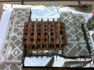
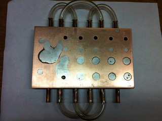
IGBT setup on water block with the 3 Phase rectifier, filter cap, snubber cap, and bus connections:
New IGBT inverter mounted: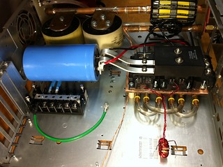
IGBT driver test setup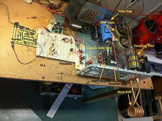
Currently I'm running two 580V 3.75uF Eurofarad tank capacitors with a .864uH work coil for an uploaded Fo of 62.5Khz. Unloaded this setup pulls 50A when feed with 120VAC single phase and 125A when feed with 240VAC single phase. With 200A IGBT's I won't be trying it on 3 phase.
Videos:
Testing 1/4" square on 120V peaking at about 35A Sparkling white hot in about 25 sec
1/4" square bar @ 25KVA
1/2" round bar @ 25KVA
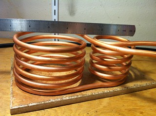
- 7/30/2012: Over the weekend I got the resonant control working with the micro controller and PLL and changed to a larger coil (4 uH) which lowered the resonant frequency to around 41KHz. I still need to do some work on the coupling transformer, I don't have an issue with the wires heating just the toroid cores.
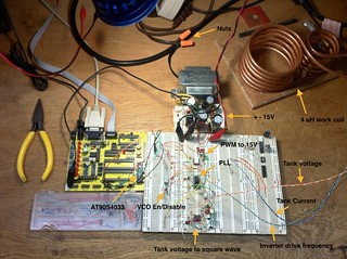
- 7-30-2012: I had a noisy ground issues that was causing the uProcessor to reset when the unit hit about 12 amps of current draw from the mains but solved it last night when I rearranged the test setup so that the control lines were all leading away from the tank. I also removed the variac and hooked directly to a 30A circuit breaker through 6AWG wire. With this setup the unit draws about 20A with a cold work piece and 30 to 32 past curie.
Something else interesting is that I no longer seem to have a problem with the toroids in the coupling transformer heating up. This was after a 5 minute run at 3000VA. Will take a closer look at this later.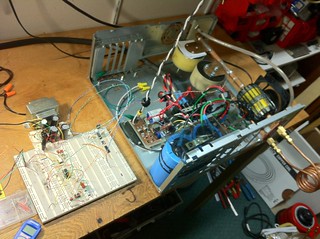
The next addition to the unit (after I complete the current sensing circuit and code) will be to replace the MOSFETs with IGBT bricks (200 or 400A). My brothers original power requirements were a bit limiting but he now has available a 240V 60A circuit so I can up this to a 15KW unit.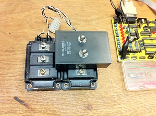
- 7/25/12: So it's been a while since my last update, I tend get caught up in the process and don't make time to document my progress. Once it's complete I'll have a nice summary of the whole project. Since the last update I made and stuffed an inverter board. This board was initially just for testing so I could complete the control logic and work with the basic signals that are present in this type of IH. Well I wasn't happy with it. I had trace heating at higher power levels and and melted solder resulted in a flash over from tank output to ground taking out a few components near it's path. I redesigned the inverter board routing the HV manually on larger bus lines, seperated the HV from LV control, and added some latch up protection on the now larger TO-220 drivers (from SOIC-8). I also made the inverter ground and LV ground connection optional and clearly defined. All signals look beautiful and I can safely run at 15Amps (off of 120V mains using the voltage doubler power supply) for long periods using the now water cooled MOSFETs. Even with the cooling water around 90-95 degrees F the FETs hover around 115-130 degrees when pulling 15A at resonance.
Flash over: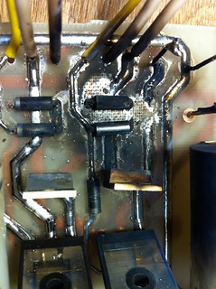
New inverter board, water block for bridge and MOSFETs, coupling tx (trying different toroids and wire), tank setup (removed loop intended for current balancing an MMC), terminal strip for connections.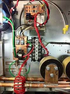
Test setup with Inverter logic drive in, Inverter current out, and tank voltage out. Will get some cleaner pics up as well as all the scope tracings.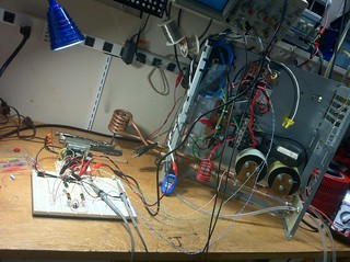
New Inverter (V2.1):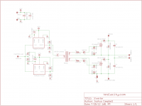
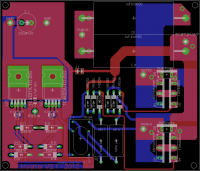
Updated eagle project files for the inverter: ]ih-inverter.zip[/file]
As always there are more pics in the Flicker album not shown here. Since these pictures I have removed one of the tank capacitors and raised the work coil inductance slightly, the resonance frequency is still around 65KHz. More to come soon on the PLL/uController resonance lock.
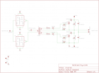
- 7/2/12: Completed initial schematic and board design for the Inverter Power Supply, Low Voltage Power Supply, & Inverter. All control logic will remain on a breadboard until I work out how I want to control resonance, manage power, and what needs monitoring. I'll make the boards on the 5th and stuff them on on the 6th when the last of the components arrive. That leaves the weekend for the fun part, putting it all together and making it work!
Images and Eagle project files:]ih-power-inverter.zip[/file]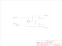
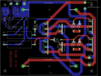
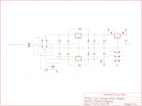
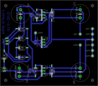
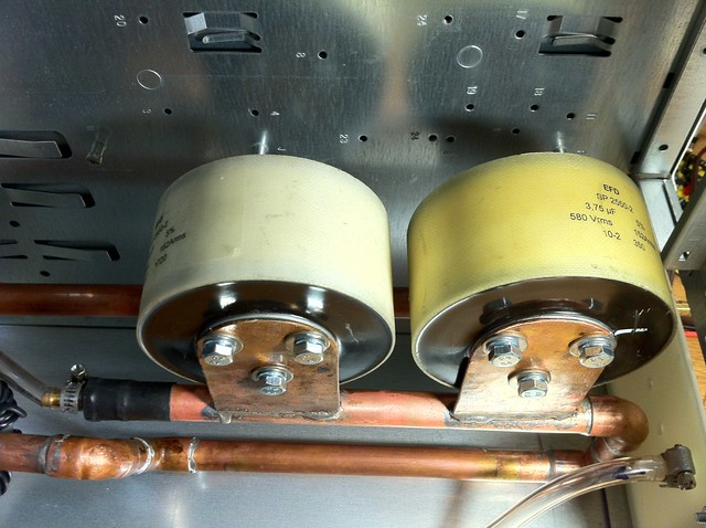
- 6/28/12: Bonded tank cap mounts to the tank cooling pipes and mounted the caps. A little No-Ox on the copper plates between the caps to keep the connection clean. The brackets are made from 1/16" rigid coper and are short to allow the capacitors to dissipate heat via the cooling water running through the pipes just below them.
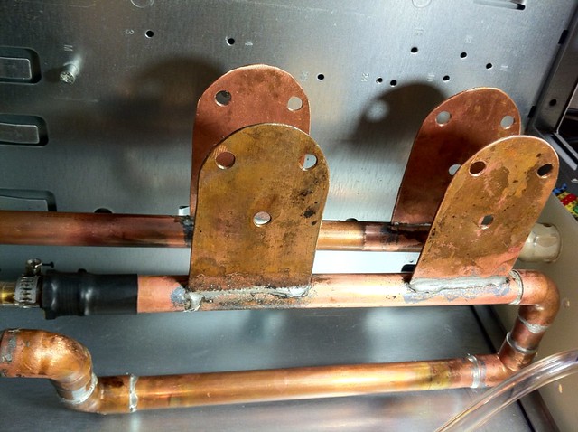
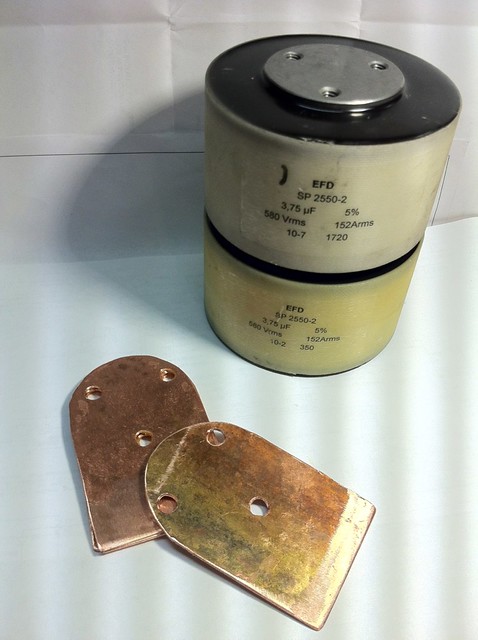
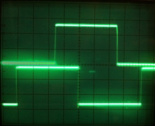
- 6/27/12: Assembled the first coupling transformer (will use litz wire when it arrives), and capacitor mounting brackets for the Eurofarad tank caps. Working on a phase monitoring set up to possibly eliminate the PLL. Basically I'm using a comparator to turn the wave form of a current transformer (at the output of the inverter going to the coupling transformer) into a square wave, changing states at the zero cross points. This is fed into one port of the uP. Another comparator set up connected across the tank capacitor sends a similar square wave to the uP, this one shows the phase of the voltage across the capacitor. Since we know that the current and voltage are in phase in the tank at resonance we can use these inputs to determine if we are at resonance and if not which way to tune. The comparators outputs are shown in the photo below, I on top and E on bottom. I'm not sure yet if I want to generate the inverter driver frequency with a uP interrupt or a VCO of some type, we'll see. I'll have schematics and results up here as soon as I complete them.

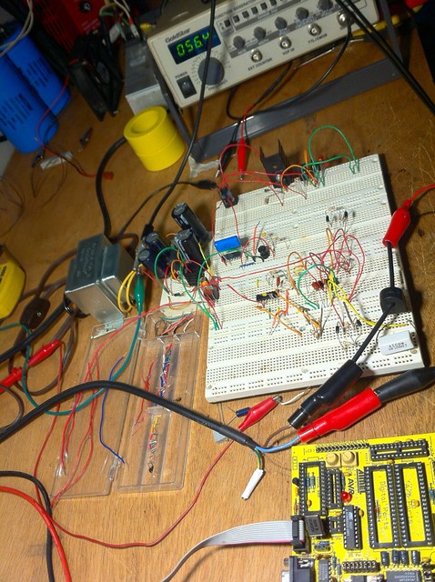
- 6/23/12 - 6/25/12: Built the PLL/uProcessor circuit on a bread board to test and work out a final schematic design for the resonant frequency range needed. (Currently 45-100KHz) - Received lots of toroids, caps, and other fun stuff, most of the parts that I don't have in stock are here now.
- 6/20/12: Received rectifiers (1000V 50A) and caps for HV supply. Wired up the HV multiplier power supply for testing. AC IN:DC OUT = about 1:2.85 so 120VAC in yields about 340VDC out.
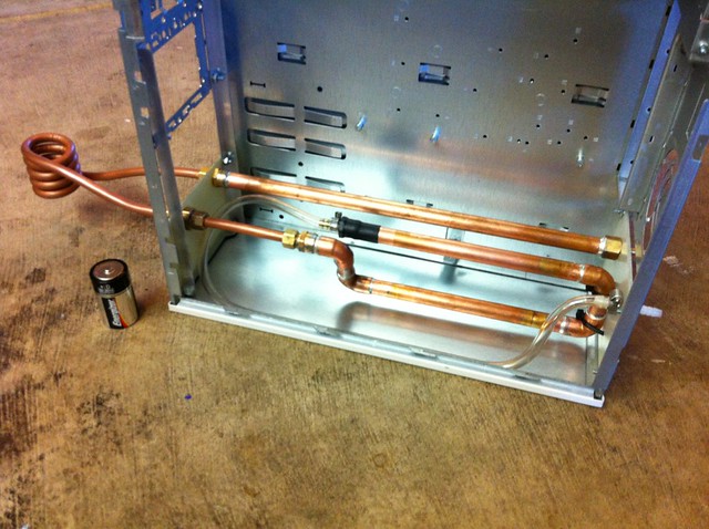
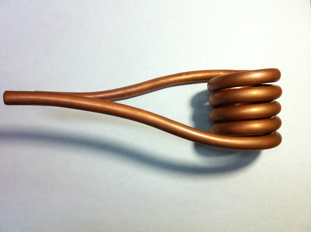
- 6/16/12 - 6/18/12: Obtained the remaining copper parts needed to assemble the tank. Cleaned out an old ATX computer case and modified to work as a case for the Induction heater. Fabricated and mounted working coil and internal plumbing for tank capacitor mounting, coupling transformer mounting, and water cooling. Most of the parts will be arriving this week form Digikey, Mouser, Newark, OnlineComponents, AliExpress, and of course eBay
Re: Induction Heater - Series Resonant - uC/PLL Tuning [ReactorForge]
Dr. ISOTOP, Tue Jun 19 2012, 04:54AM
How are you planning to control power? Bus voltage control, phase shifting the legs, detuning, pulse-skipping?
Dr. ISOTOP, Tue Jun 19 2012, 04:54AM
How are you planning to control power? Bus voltage control, phase shifting the legs, detuning, pulse-skipping?
Re: Induction Heater - Series Resonant - uC/PLL Tuning [ReactorForge]
Josh Campbell, Tue Jun 19 2012, 05:30PM
I'll most likely adjust the phase angle before the HV bridge rectifier using large Eupec PowerBlock SCR's:
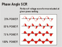
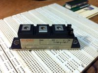
Other options I will want to try are making a fully-controled SCR bridge rectifier in place of the standard one. Or making a variable tap coupling transformer.
Did you ever incorporate any type of power control into yours, have any suggestions or pointers?
Josh Campbell, Tue Jun 19 2012, 05:30PM
I'll most likely adjust the phase angle before the HV bridge rectifier using large Eupec PowerBlock SCR's:


Other options I will want to try are making a fully-controled SCR bridge rectifier in place of the standard one. Or making a variable tap coupling transformer.
Did you ever incorporate any type of power control into yours, have any suggestions or pointers?
Re: Induction Heater - Series Resonant - uC/PLL Tuning [ReactorForge]
Dr. ISOTOP, Tue Jun 19 2012, 08:33PM
I had a 4-tap transformer to control power for different work piece materials, and I detuned the driver for finer control. Its not good for the bridge, but I was using watercooled CM400's, which dealt with it fine.
Dr. ISOTOP, Tue Jun 19 2012, 08:33PM
2bytes wrote ...
I'll most likely adjust the phase angle before the HV bridge rectifier using large Eupec PowerBlock SCR's:


Other options I will want to try are making a fully-controled SCR bridge rectifier in place of the standard one. Or making a variable tap coupling transformer.
Did you ever incorporate any type of power control into yours, have any suggestions or pointers?
I'll most likely adjust the phase angle before the HV bridge rectifier using large Eupec PowerBlock SCR's:


Other options I will want to try are making a fully-controled SCR bridge rectifier in place of the standard one. Or making a variable tap coupling transformer.
Did you ever incorporate any type of power control into yours, have any suggestions or pointers?
I had a 4-tap transformer to control power for different work piece materials, and I detuned the driver for finer control. Its not good for the bridge, but I was using watercooled CM400's, which dealt with it fine.
Re: Induction Heater - Series Resonant - uC/PLL Tuning [ReactorForge]
Dr. Dark Current, Sat Jul 14 2012, 10:11AM
Remember to use an inductor if you are controlling a capacitive load with a SCR.
Dr. Dark Current, Sat Jul 14 2012, 10:11AM
Remember to use an inductor if you are controlling a capacitive load with a SCR.
Re: Induction Heater - Series Resonant - uC/PLL Tuning [ReactorForge]
Josh Campbell, Wed Jul 25 2012, 07:32PM
Josh Campbell, Wed Jul 25 2012, 07:32PM
Dr. Dark Current wrote ...
Remember to use an inductor if you are controlling a capacitive load with a SCR.
Definitely! But thank you for the reminder, sometimes I'm only reminded of subtle things like this AFTER catastrophic component failure. I would like to actually cancel out any reactance using a boost type converter and correct the power factor to 1 so the SCR's would only see a resistive load. But this is obviously not a major requirement in order for the IH to work properly so it will probably be the very last thing I do, if I do it at al, for now denting above resonance works just fine.Remember to use an inductor if you are controlling a capacitive load with a SCR.
Re: Induction Heater - Series Resonant - uC/PLL Tuning [ReactorForge]
Josh Campbell, Thu Aug 09 2012, 11:30PM
I was really looking for a reason to use these SCRs in something but I don't think I want to use them just for the sake of using them when driving an IGBT is so much easier and more flexible. I am going to test using an IGBT to PWM the DC bus before the filter cap, will update with results soon. I do need to do some type of current limiting for sure since when connected to 240V it pulls about 125 amps with no work piece to load it, which is about twice what my brother has available where this is going.
Check out the new vids, nothing new really (glowing stuff) but it does show the working PLL/uP tuning in use. I'll get some videos of the scope and the IH together while in use to show that part a little better. One button operation is really nice, rather not say how many MOSFETs I blew tuning it manually during testing. :)
Videos:
Testing 1/4" square on 120V peaking at about 35A (Sparkling white hot in about 25 sec)
1/4" square bar @ 25KVA
1/2" round bar @ 25KVA
Re: Induction Heater - Series Resonant - uC/PLL Tuning [ReactorForge]
Gabriel35, Fri Aug 10 2012, 12:21PM
Pretty Impressive!!!
I hope that someday I can reach something like that!!!
Gabriel35, Fri Aug 10 2012, 12:21PM
Pretty Impressive!!!
I hope that someday I can reach something like that!!!
Re: Induction Heater - Series Resonant - uC/PLL Tuning [ReactorForge]
Josh Campbell, Fri Aug 10 2012, 11:19PM
Appreciate it Gabriel, once I finish the closed loop hall effect current sensing/limiting portion I'll get the rest of the schematics and pcb layouts up along with descriptions and walk throughs. And after I refine the Atmel code I'll post it up here as well. So far I've made the prototype boards but once I get a revised "final" version I'll have some made and probably post the rest of them up here just to offset the cost of ordering multiples. As of now it will have a low voltage ps board and then all the control and driver circuitry on another board. With a possibility of having the driver circuitry on it's own board as well, we'll see, there's not much to that part now that I'm using IGBT's.
Josh Campbell, Fri Aug 10 2012, 11:19PM
Gabriel35 wrote ...
Pretty Impressive!!!
I hope that someday I can reach something like that!!!
Pretty Impressive!!!
I hope that someday I can reach something like that!!!
Appreciate it Gabriel, once I finish the closed loop hall effect current sensing/limiting portion I'll get the rest of the schematics and pcb layouts up along with descriptions and walk throughs. And after I refine the Atmel code I'll post it up here as well. So far I've made the prototype boards but once I get a revised "final" version I'll have some made and probably post the rest of them up here just to offset the cost of ordering multiples. As of now it will have a low voltage ps board and then all the control and driver circuitry on another board. With a possibility of having the driver circuitry on it's own board as well, we'll see, there's not much to that part now that I'm using IGBT's.
Re: Induction Heater - Series Resonant - uC/PLL Tuning [ReactorForge]
Jrz126, Sat Aug 11 2012, 07:05PM
Looks great.
Where'd you get the ferrite cores for the coupling transformer? What material is it?
Jrz126, Sat Aug 11 2012, 07:05PM
Looks great.
Where'd you get the ferrite cores for the coupling transformer? What material is it?
Re: Induction Heater - Series Resonant - uC/PLL Tuning [ReactorForge]
Josh Campbell, Sat Aug 11 2012, 08:33PM
The grey ones are iron powder toroids material type 3 with a frequency range of 50 to 500KHz distributed by Amidon.
T225-3 Iron Powder Toroid
The yellow ones are also iron powder toroids material type 26 for use as high temperature transformer cores. They are similar in quality to Micrometal's type 26 cores but I'm unsure of the manufacturer. These are nice to have around as they take a lot to saturate at sub 100KHz Fo ranges.
AT225-26B High Temperature Iron Powder Ferrite Core
The coupling transformer configuration isn't final but it is working very well at high power levels. For example running near 10KVA (240VAC in limited to 40A) the toroid core never passed 115 degrees F on long runs. I have an assortment of power conversion rated powdered iron toroid cores from Micrometals that I need to experiment with. I may end up using a type 52 for the final stage gate transformer (that's actually what's on it now) and for the coupling/matching transformer as they seem to perform much better than the type 26 material up to 250KHz and have lower losses than the 26 below 100KHz (Their design tool is pretty useful.)
I have a BOM of all the parts and suppliers that I'll list once I finalize it all.
Josh Campbell, Sat Aug 11 2012, 08:33PM
Jrz126 wrote ...
Looks great.
Where'd you get the ferrite cores for the coupling transformer? What material is it?
Looks great.
Where'd you get the ferrite cores for the coupling transformer? What material is it?
The grey ones are iron powder toroids material type 3 with a frequency range of 50 to 500KHz distributed by Amidon.
T225-3 Iron Powder Toroid
The yellow ones are also iron powder toroids material type 26 for use as high temperature transformer cores. They are similar in quality to Micrometal's type 26 cores but I'm unsure of the manufacturer. These are nice to have around as they take a lot to saturate at sub 100KHz Fo ranges.
AT225-26B High Temperature Iron Powder Ferrite Core
The coupling transformer configuration isn't final but it is working very well at high power levels. For example running near 10KVA (240VAC in limited to 40A) the toroid core never passed 115 degrees F on long runs. I have an assortment of power conversion rated powdered iron toroid cores from Micrometals that I need to experiment with. I may end up using a type 52 for the final stage gate transformer (that's actually what's on it now) and for the coupling/matching transformer as they seem to perform much better than the type 26 material up to 250KHz and have lower losses than the 26 below 100KHz (Their design tool is pretty useful.)
I have a BOM of all the parts and suppliers that I'll list once I finalize it all.
Re: Induction Heater - Series Resonant - uC/PLL Tuning [ReactorForge]
teravolt, Mon Aug 13 2012, 03:59AM
do your tank caps get hot and are you still just using the one
teravolt, Mon Aug 13 2012, 03:59AM
do your tank caps get hot and are you still just using the one
Re: Induction Heater - Series Resonant - uC/PLL Tuning [ReactorForge]
Josh Campbell, Mon Aug 13 2012, 02:21PM
Right now I'm using both of them since I have a a smaller H work coil attached. With both of them attached and running from 240VAC mains limited to 50-60A they run only slightly warm, showing around 115-130° F on the IR thermometer. The front cap does get a bit more warm than the back one, the next tank I build I'll put them equidistant from the work coil rather than front to back like they are now. I'll post some vids or pics of a long run and show the temperatures of the working components.
Re: Induction Heater - Series Resonant - uC/PLL Tuning [ReactorForge]
teravolt, Mon Aug 13 2012, 04:52PM
if you switch the caps will the front one still get hot? what do you think the circulating current is?
teravolt, Mon Aug 13 2012, 04:52PM
if you switch the caps will the front one still get hot? what do you think the circulating current is?
Re: Induction Heater - Series Resonant - uC/PLL Tuning [ReactorForge]
Josh Campbell, Mon Aug 13 2012, 07:52PM
If the caps are arranged to be an equal distance from the work coil then they will heat evenly since the current will not favor one or the other as is the case with one being closer. (The cap closest to the work coil will be carrying the most current.)
When running at 10KVA my 300A clamp on meter pegs out hard when attached just behind the work coil. I'll do some tests with the variac at reduced power levels and plot a graph of tank current as supply voltage increases.
I have some hall effect current sensors on the way that I will be using to determine mains draw current and maybe for fun, tank current at high power levels.
Re: Induction Heater - Series Resonant - uC/PLL Tuning [ReactorForge]
Dr. Dark Current, Mon Aug 13 2012, 09:05PM
You can measure the current by putting a small cap in parallel to the tank caps and measure the current through it (if the cap is 1000 times smaller than the tank one, you will get 1000 times lower current).
Dr. Dark Current, Mon Aug 13 2012, 09:05PM
You can measure the current by putting a small cap in parallel to the tank caps and measure the current through it (if the cap is 1000 times smaller than the tank one, you will get 1000 times lower current).
Re: Induction Heater - Series Resonant - uC/PLL Tuning [ReactorForge]
Josh Campbell, Tue Aug 14 2012, 02:14PM
I'll try that, although I may have to wait until the caps are rearranged to be an equal distance from the coil or take one out since the placement of the small cap relative to the tank cap(s) would likely make a difference in current reading. I should also be able to work it out mathematically since I know the input V & I along with the peak tank voltage from the scope readings. Hall effect sensors will be here today too!
I'm working on finishing the control board to get everything off of the breadboard, once that is finished I'll have more time to look at interesting things like tank current.
Josh Campbell, Tue Aug 14 2012, 02:14PM
Dr. Dark Current wrote ...
You can measure the current by putting a small cap in parallel to the tank caps and measure the current through it (if the cap is 1000 times smaller than the tank one, you will get 1000 times lower current).
You can measure the current by putting a small cap in parallel to the tank caps and measure the current through it (if the cap is 1000 times smaller than the tank one, you will get 1000 times lower current).
I'll try that, although I may have to wait until the caps are rearranged to be an equal distance from the coil or take one out since the placement of the small cap relative to the tank cap(s) would likely make a difference in current reading. I should also be able to work it out mathematically since I know the input V & I along with the peak tank voltage from the scope readings. Hall effect sensors will be here today too!
I'm working on finishing the control board to get everything off of the breadboard, once that is finished I'll have more time to look at interesting things like tank current.
Re: Induction Heater - Series Resonant - uC/PLL Tuning [ReactorForge]
klugesmith, Tue Aug 14 2012, 03:15PM
For tank current measurement, a permanently installed Rogowski coil might be well suited.
Its sensitivity (in units of nH) can be calculated from geometry. An integrator to give you voltage proportional to current could be passive and trivial. Especially in your narrow frequency range of interest.
If you're interested, I could give you one of my PCB Rogowski coils as described here:

Re: Induction Heater - Series Resonant - uC/PLL Tuning [ReactorForge]
Josh Campbell, Tue Aug 14 2012, 03:47PM
A standard closed loop CT would obviously not work due to inductive heating of the core, my clamp on was quite hot after just clamping it on and removing it in under a second or two. But an open loop Rogowski coil would work great, good idea! And since the Rog coil has no iron core to saturate, it's response is very fast. I used something similar to measure magnetic fields in another project. The pcb is a very cool idea but I think i would rather have the coil on a flexible substrate so I could wrap it around the 1/2" tank bus tube. I wrapped the wire on a 1/4" flexible pvc tube in the past.
Josh Campbell, Tue Aug 14 2012, 03:47PM
klugesmith wrote ...
For tank current measurement, a permanently installed Rogowski coil might be well suited.
Its sensitivity (in units of nH) can be calculated from geometry. An integrator to give you voltage proportional to current could be passive and trivial. Especially in your narrow frequency range of interest.
If you're interested, I could give you one of my PCB Rogowski coils as described here:

A standard closed loop CT would obviously not work due to inductive heating of the core, my clamp on was quite hot after just clamping it on and removing it in under a second or two. But an open loop Rogowski coil would work great, good idea! And since the Rog coil has no iron core to saturate, it's response is very fast. I used something similar to measure magnetic fields in another project. The pcb is a very cool idea but I think i would rather have the coil on a flexible substrate so I could wrap it around the 1/2" tank bus tube. I wrapped the wire on a 1/4" flexible pvc tube in the past.
Re: Induction Heater - Series Resonant - uC/PLL Tuning [ReactorForge]
Gabriel35, Tue Sept 04 2012, 12:02PM
How are you measuring those waveforms on your scope? Using Differential probes right?
Gabriel35, Tue Sept 04 2012, 12:02PM
How are you measuring those waveforms on your scope? Using Differential probes right?
Re: Induction Heater - Series Resonant - uC/PLL Tuning [ReactorForge]
Josh Campbell, Tue Sept 04 2012, 03:52PM
One would think so but no. The my differential probe has been shot for a while, a scope upgrade is in my near future so I'm waiting until then to get new probes. I just isolated the scopes ground and was careful which grounds I connected together with the scope probes. I usually leave my o-scope floating anyway to avoid ground loops.
Josh Campbell, Tue Sept 04 2012, 03:52PM
Gabriel35 wrote ...
How are you measuring those waveforms on your scope? Using Differential probes right?
How are you measuring those waveforms on your scope? Using Differential probes right?
One would think so but no. The my differential probe has been shot for a while, a scope upgrade is in my near future so I'm waiting until then to get new probes. I just isolated the scopes ground and was careful which grounds I connected together with the scope probes. I usually leave my o-scope floating anyway to avoid ground loops.
Re: Induction Heater - Series Resonant - uC/PLL Tuning [ReactorForge]
teravolt, Wed Sept 05 2012, 04:14AM
hi 2bytes I recently aquired some celem caps and I am trying to make a decision on a 4046 circiut and I am interested how you integrated the pll with the micro and did you use a arduino?
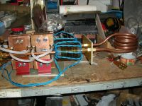
it could have other applications for driving other circuits like DRSSTC
what is the advantages of using a micro with the 4046?
teravolt, Wed Sept 05 2012, 04:14AM
hi 2bytes I recently aquired some celem caps and I am trying to make a decision on a 4046 circiut and I am interested how you integrated the pll with the micro and did you use a arduino?

it could have other applications for driving other circuits like DRSSTC
what is the advantages of using a micro with the 4046?
Re: Induction Heater - Series Resonant - uC/PLL Tuning [ReactorForge]
Josh Campbell, Sun Sept 09 2012, 05:46PM
Hey Nathan sorry for the delay, I've been working on a really fun RGB LED project for a client and got side tracked from HV. :)
I'll post my current control schematic and a couple new photos in the OP. Basically I just have the uC inserted as the low pass filter for the PLL. The micro controller takes in the output of the the Phase Comparator I out through a low pass filter. From this we know what the current phase difference is between Fo (inverter drive frequency) and Tce (Voltage across tank the tank capacitor). As I'm sure you already know the tank voltage should lag behind the inverter drive F by 90 degrees at resonance. The uC simply outputs an analog voltage via filtered PWM to feed VCO in on the PLL. This allows us to do much more than a simple low pass filter. Soft starting/stoping, and current control by detuning to name a couple.
The original code was written in C using AVR Studio 6 when I was using the bread board and STK200. I moved to Bascom for the new board once I knew the hardware was working well because it makes it so quick and easy. Although the resulting code is not as optimized imo so I will eventually rewrite the basic for the final product in C.
I'm not a fan of Arduino, I guess because I've been using Atmel products for 10+ years, long before that thing came along. Plus I just make my own boards or have them made for less than the cost of an Arduino. But there is definitely value in them for the beginner or when in a hurry I suppose.
Josh Campbell, Sun Sept 09 2012, 05:46PM
teravolt wrote ...
hi 2bytes I recently aquired some celem caps and I am trying to make a decision on a 4046 circiut and I am interested how you integrated the pll with the micro and did you use a arduino?

it could have other applications for driving other circuits like DRSSTC
what is the advantages of using a micro with the 4046?
hi 2bytes I recently aquired some celem caps and I am trying to make a decision on a 4046 circiut and I am interested how you integrated the pll with the micro and did you use a arduino?

it could have other applications for driving other circuits like DRSSTC
what is the advantages of using a micro with the 4046?
Hey Nathan sorry for the delay, I've been working on a really fun RGB LED project for a client and got side tracked from HV. :)
I'll post my current control schematic and a couple new photos in the OP. Basically I just have the uC inserted as the low pass filter for the PLL. The micro controller takes in the output of the the Phase Comparator I out through a low pass filter. From this we know what the current phase difference is between Fo (inverter drive frequency) and Tce (Voltage across tank the tank capacitor). As I'm sure you already know the tank voltage should lag behind the inverter drive F by 90 degrees at resonance. The uC simply outputs an analog voltage via filtered PWM to feed VCO in on the PLL. This allows us to do much more than a simple low pass filter. Soft starting/stoping, and current control by detuning to name a couple.
The original code was written in C using AVR Studio 6 when I was using the bread board and STK200. I moved to Bascom for the new board once I knew the hardware was working well because it makes it so quick and easy. Although the resulting code is not as optimized imo so I will eventually rewrite the basic for the final product in C.
I'm not a fan of Arduino, I guess because I've been using Atmel products for 10+ years, long before that thing came along. Plus I just make my own boards or have them made for less than the cost of an Arduino. But there is definitely value in them for the beginner or when in a hurry I suppose.
Re: Induction Heater - Series Resonant - uC/PLL Tuning [ReactorForge]
Josh Campbell, Wed Sept 12 2012, 04:40PM
BTW Nathan, that's a very nice setup.
Have you tested that push/pull coupling transformer setup yet? Would be interested to see how well that works. What type of cores are those, did you pick them up for this use or just have them lying around? Same thing with the Celem caps, did you source them just for this or just happen upon them? Sure would be nice if those were available as surplus somewhere.
Re: Induction Heater - Series Resonant - uC/PLL Tuning [ReactorForge]
teravolt, Mon Sept 17 2012, 03:04AM
hi Josh, sorry for the delay, I want to do the same thing you are doing but I want to use Raspberry Pi and python to make the same sort of driver.
I haven't applied the driver yet I ame looking at what type of circuit to drive it. I am not shure of what types of cores they are I know they were used for some sort of pulsed transformer aplication and I picked them up as surplus. I have used a signal generator and the resonant frequency is around 10k unloaded. the celems I got on ebay and I snached them up as soon as I soon as I could. The tank circuit has been upraded since the last picture and I will show later I added a mica wrap 3uf+celem 2uf+celem .1uf is my total capacitance. when I get back from yosemite I'll do another picture. what is the resonant freq unloaded. I cind of wanted ti do what Linas did with his

Re: Induction Heater - Series Resonant - uC/PLL Tuning [ReactorForge]
Josh Campbell, Mon Sept 17 2012, 03:26AM
HA, I was thinking of using a RasPi in my next version to talk to an FPGA so I could deal with the phase relation ship in real time. Although I think it might be a bit overkill and probably wont use it, a uController to interface with the FPGA is almost always sufficient. But who knows, I did already by this nice case for it from Polycase (highly recommended). Linas might have the better idea, just using a prebuilt controller, a lot of the buck/boost PF correction controllers for florescent lights would work too. They have every feature and more built in that you would need to run an IH. I really just wanted to do it myself in the raw to see what was happening, plus I like PLLs and micro controllers, you know getting your hands dirty and wrapping your mind around the fundamentals.
Have fun in Yosemite (if your going for fun) and keep us updated on your IH!
Re: Induction Heater - Series Resonant - uC/PLL Tuning [ReactorForge]
teravolt, Mon Sept 17 2012, 02:59PM
I read some whare that a RPi has lots of interup cycles and that if real time controle is neaded that adruino is better. I am wating for the gert board wich has a aduino chip on it and that could be used to run the 4046 and make adjustments while rpi monitors. FPGA is definatly the way to go it seams. I am realy a newbe when it comes to programing but I know how to hardware. I thought pyton and C and linux are handy to know. maby it is pausible to make a PLL that is aduino based or like you say using a FPGA. micro mixed with analog is good. when I refired to Linas's thread he has some of thos poly caps that you use plus a celem and mixing caps can be tricky. In his setup I think that his poly caps do moast of the work because here XL is 10 times less than the celem and I want to balence it more and I am not shure if it is necisary with the celem. I have wated a long time to find some Celem caps that are afordable.
yosemite is nce and I haven't cought the Haunta Virus hear in curry village yet I hope
Re: Induction Heater - Series Resonant - uC/PLL Tuning [ReactorForge]
teravolt, Wed Sept 19 2012, 01:09AM
Hi Josh, here is a picture of my additions next week I hope to work on the igbt driver
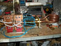
teravolt, Wed Sept 19 2012, 01:09AM
Hi Josh, here is a picture of my additions next week I hope to work on the igbt driver

Re: Induction Heater - Series Resonant - uC/PLL Tuning [ReactorForge]
teravolt, Wed Sept 19 2012, 02:14AM
oops sorry for duble poast
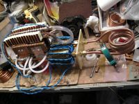
teravolt, Wed Sept 19 2012, 02:14AM
oops sorry for duble poast

Re: Induction Heater - Series Resonant - uC/PLL Tuning [ReactorForge]
Josh Campbell, Wed Sept 19 2012, 03:11AM
That's looking great! I'm really interested in your push/pull coupler. Did you see that somewhere else or is that a Nathan original? Also what is that MMC on top of your Celems, are you trying to lower your resonant frequency with those? Or is it a DC filter array or snubber network? Also if that current clamp you have behind your work coil is an iron core you'll melt it, trust me. ;) You'll have to measure tank current by another means, there are a couple methods listed above, unless your running low power of course.
Just noticed you used compression connections, the flare tool is $15-30 and it's worth it. I highly recommend flare connections over compression.
Re: Induction Heater - Series Resonant - uC/PLL Tuning [ReactorForge]
teravolt, Thu Sept 20 2012, 04:38AM
yah the push-pull couplier so fare is is a nathan special. I wanted to add as much ferite as pausible. With all those wires I can do 9:1, 18:1, 36:1. the mmc on the top has a ESR of 4m ohm at 3uf. it may not be necisary at all I just want about 2k amp circulating current.it is in paralell wit he celem's for more circulating current The green current transformer is a person transformer. I think that it is .1v per amp. I am not shure of its construction. I'll just use it for diagnotics and tuning, it will tell me the current wave form for my o-scope.
the compresion fittings are 1/2"swagelock and should be enough for the moment. I agree that a flaired coupling alows for better contact and I my go with at a later date
Re: Induction Heater - Series Resonant - uC/PLL Tuning [ReactorForge]
mohiuddinHimel, Sun Oct 07 2012, 11:02AM
Hey, your project is the most neat and powerful i've ever seen.
I am very much interested to build a similar one of 15KVA. I've made a capacitor bank capable of 120/150 amps. The combined rating is 3.8 uF 1000V. Just need to get those bigAss IGBT's, Coupling transformer. I have a AVR development board to try the pll self locking and soft start. The current limiting switching is just AWESOME!! Which eliminates the requirement of a large Transformer or Variac !!!!
In my country the mains are 240 V ac. Can i hook up the mains directly to the bridge rectifier????
For snubber cap what kind of capacitor should be used???
Thanks in advance :)
Re: Induction Heater - Series Resonant - uC/PLL Tuning [ReactorForge]
Josh Campbell, Sun Oct 07 2012, 08:30PM
Hi Mohiuddin, thanks for the complements. There is plenty of room for improvement, namely in the tank setup, driver section and cleaning up the control layout.
I was looking at your capacitor bank the other day when you posted it, very creative! You will want to make sure your connection to the bank right in the center of each side so the reactive load will be distributed properly. (Unlike mine where I have an inline setup: cap > cap > coil. Although those big caps handle it fine at the relatively moderate power levels I'm running.)
Do you have a target resonant frequency?
The AVR controlled PLL is pretty simple to setup, and if you do it cleanly it even works on a breadboard. Let me know if you hit any snags and I'll do what I can to help out.
I really wasn't happy with the closed loop current limiting set up I had. Which was basically this: line current read with a closed loop ratio-metric hall effect sensor, integrated, rectified, and converted to a dc voltage. Having a response time of a couple hundred uSeconds after conditioning. The dc voltage was then read by the processor at the same time that the phase value was read from the PLL comp output. In the control loop where the processor would adjust the PWM output for the VCO voltage if the current was equal to or above where the software limit was set it would not allow the VCO to be lowered. If it was above the limit it would force a positive offset, raising the VCO frequency regardless of whether or not the phase was above resonance. I had issues with oscillation that were difficult to deal with because it's behavior different when there was a work piece in. The size and temperature of the work piece also affected it. So I'm going another route...
Rather than limit the current with an above resonance offset. I'm going to use a variable duty cycle to drive the IGBT's while keeping it at resonance. This way the tank is always pulling it's maximum current draw and is always at resonance. So it's maximum current will be a celling set by the duty cycle of the inverter rather than trying to back down from a celling so oscillation will be impossible.
There are a few changes that need to be made first which I'm working on now. The PLL's VCO can not be used because it is locked into 50% duty cycle operation. The driver setup I'm using will not work either since it is also setup for use with a 50% duty cycle waveform. I'm changing over from the easy MosFET driver/pulse transformer type to a Hybrid-IC opto-isolated driver. This will allow me to set the on and off time independently and will also greatly increase my frequency range since I will not be dependent on a pulse transformer. Another benefit here is that I will be able to add in desaturation detection to detect/stop short circuits. Lots of other cool stuff that I'll go into once it's done.
Yes you can connect your mains directly to the bridge rectifier as long as it is properly rated. Right now my IH is running on 240V using a 100A 1600V 3-Phase rectifier.
As far as the snubber cap goes you generally want a low henry cap very close to the DC bus (right on the IGBT preferably). It should be rated nearly 3-4 times the maximum bus voltage. It's value can range from .1 to 20uF depending on your bus voltage, ripple, inverter dv/dt, and current draw.
This defiantly is not as easy to build as some of the self resonant IHs out there but I have always had trouble getting those to resonate cleanly at high current. Sacrificed my share of FETs to the trash. (Until canceling the antiparallel diode and replacing it with a faster one.) :)
Josh Campbell, Sun Oct 07 2012, 08:30PM
mohiuddinHimel wrote ...
Hey, your project is the most neat and powerful i've ever seen.
I am very much interested to build a similar one of 15KVA. I've made a capacitor bank capable of 120/150 amps. The combined rating is 3.8 uF 1000V. Just need to get those bigAss IGBT's, Coupling transformer. I have a AVR development board to try the pll self locking and soft start. The current limiting switching is just AWESOME!! Which eliminates the requirement of a large Transformer or Variac !!!!
In my country the mains are 240 V ac. Can i hook up the mains directly to the bridge rectifier????
For snubber cap what kind of capacitor should be used???
Thanks in advance :)
Hi Mohiuddin, thanks for the complements. There is plenty of room for improvement, namely in the tank setup, driver section and cleaning up the control layout.
I was looking at your capacitor bank the other day when you posted it, very creative! You will want to make sure your connection to the bank right in the center of each side so the reactive load will be distributed properly. (Unlike mine where I have an inline setup: cap > cap > coil. Although those big caps handle it fine at the relatively moderate power levels I'm running.)
Do you have a target resonant frequency?
The AVR controlled PLL is pretty simple to setup, and if you do it cleanly it even works on a breadboard. Let me know if you hit any snags and I'll do what I can to help out.
I really wasn't happy with the closed loop current limiting set up I had. Which was basically this: line current read with a closed loop ratio-metric hall effect sensor, integrated, rectified, and converted to a dc voltage. Having a response time of a couple hundred uSeconds after conditioning. The dc voltage was then read by the processor at the same time that the phase value was read from the PLL comp output. In the control loop where the processor would adjust the PWM output for the VCO voltage if the current was equal to or above where the software limit was set it would not allow the VCO to be lowered. If it was above the limit it would force a positive offset, raising the VCO frequency regardless of whether or not the phase was above resonance. I had issues with oscillation that were difficult to deal with because it's behavior different when there was a work piece in. The size and temperature of the work piece also affected it. So I'm going another route...
Rather than limit the current with an above resonance offset. I'm going to use a variable duty cycle to drive the IGBT's while keeping it at resonance. This way the tank is always pulling it's maximum current draw and is always at resonance. So it's maximum current will be a celling set by the duty cycle of the inverter rather than trying to back down from a celling so oscillation will be impossible.
There are a few changes that need to be made first which I'm working on now. The PLL's VCO can not be used because it is locked into 50% duty cycle operation. The driver setup I'm using will not work either since it is also setup for use with a 50% duty cycle waveform. I'm changing over from the easy MosFET driver/pulse transformer type to a Hybrid-IC opto-isolated driver. This will allow me to set the on and off time independently and will also greatly increase my frequency range since I will not be dependent on a pulse transformer. Another benefit here is that I will be able to add in desaturation detection to detect/stop short circuits. Lots of other cool stuff that I'll go into once it's done.
Yes you can connect your mains directly to the bridge rectifier as long as it is properly rated. Right now my IH is running on 240V using a 100A 1600V 3-Phase rectifier.
As far as the snubber cap goes you generally want a low henry cap very close to the DC bus (right on the IGBT preferably). It should be rated nearly 3-4 times the maximum bus voltage. It's value can range from .1 to 20uF depending on your bus voltage, ripple, inverter dv/dt, and current draw.
This defiantly is not as easy to build as some of the self resonant IHs out there but I have always had trouble getting those to resonate cleanly at high current. Sacrificed my share of FETs to the trash. (Until canceling the antiparallel diode and replacing it with a faster one.) :)
Re: Induction Heater - Series Resonant - uC/PLL Tuning [ReactorForge]
mohiuddinHimel, Mon Oct 08 2012, 09:04AM
hey bro, thanks a lot for the feedback
The duty cycle current limiting topology sounds damn good to me...it's even less complicated to establish as the whole thing will be done inside the uC. But in that case as you've said, the gate drive transformer cant be used.
I've made a circuit for variable duty cycle switching. Its a full bridge inverter. Take a look if it can be used. It needs some modification to drive large IGBTs.
But i'll finish my ZVS first. This way i'll be able to test my work coil and capacitor bank.
After the ZVS i'll go straight for the high power unit. If lucky i'll get some celem/ eurofarad caps for the tank.
Lots of works to do. cheers !!

Re: Induction Heater - Series Resonant - uC/PLL Tuning [ReactorForge]
mohiuddinHimel, Mon Oct 08 2012, 09:18AM
i'll keep you updated as the project goes on
mohiuddinHimel, Mon Oct 08 2012, 09:18AM
i'll keep you updated as the project goes on
Re: Induction Heater - Series Resonant - uC/PLL Tuning [ReactorForge]
Josh Campbell, Mon Jan 28 2013, 04:17AM
Hey Mohiuddin, make any progress?
I tried pulse skipping as a power control method again this time with a better zero cross detector and a bigger TRIAC. I still did not like the results though. With or with out a filter cap on the HV rectifier the control was not very linear. I have settle on phase shifting one side of the full bridge (see update in OP).
I basically divided the 60Hz pulse change up into 8 pulse sections. I had a byte who's bits controlled if a pulse was on or off during each of the 8 steps. So the byte would just be continually rotated, if the sampled bit was a 1 the DIAC would turn the TRIAC on, if it was a 0 it would leave it off.
The 9 different power levels were:
If Pwr_level = 0 Then Pwr = &B00000000
If Pwr_level = 1 Then Pwr = &B00000010
If Pwr_level = 2 Then Pwr = &B00010001
If Pwr_level = 3 Then Pwr = &B01001001
If Pwr_level = 4 Then Pwr = &B01010101
If Pwr_level = 5 Then Pwr = &B10111010
If Pwr_level = 6 Then Pwr = &B10111011
If Pwr_level = 7 Then Pwr = &B11111011
If Pwr_level = 8 Then Pwr = &B11111111
So each level would just add one more cycle to the 8 bit group, keeping them somewhat evenly spaced.
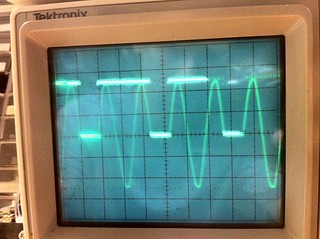
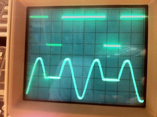
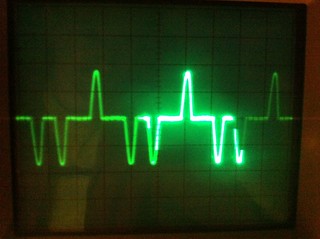
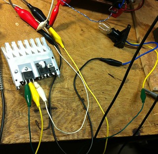
Video showing each of the 9 steps -
Another concept I tried:
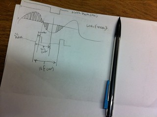
Using a varying duty cycle PWM I disabled the output of the gate drives. I tried centering the disabling pulse in the middle of each phase, at the end, and beginning. None of which produced satisfactory results. The power level was again choppy and very non-liniear. The phase shifting method is definitely the way to go for smooth linear control.
Josh Campbell, Mon Jan 28 2013, 04:17AM
Hey Mohiuddin, make any progress?
I tried pulse skipping as a power control method again this time with a better zero cross detector and a bigger TRIAC. I still did not like the results though. With or with out a filter cap on the HV rectifier the control was not very linear. I have settle on phase shifting one side of the full bridge (see update in OP).
I basically divided the 60Hz pulse change up into 8 pulse sections. I had a byte who's bits controlled if a pulse was on or off during each of the 8 steps. So the byte would just be continually rotated, if the sampled bit was a 1 the DIAC would turn the TRIAC on, if it was a 0 it would leave it off.
The 9 different power levels were:
If Pwr_level = 0 Then Pwr = &B00000000
If Pwr_level = 1 Then Pwr = &B00000010
If Pwr_level = 2 Then Pwr = &B00010001
If Pwr_level = 3 Then Pwr = &B01001001
If Pwr_level = 4 Then Pwr = &B01010101
If Pwr_level = 5 Then Pwr = &B10111010
If Pwr_level = 6 Then Pwr = &B10111011
If Pwr_level = 7 Then Pwr = &B11111011
If Pwr_level = 8 Then Pwr = &B11111111
So each level would just add one more cycle to the 8 bit group, keeping them somewhat evenly spaced.


Video showing each of the 9 steps -

Another concept I tried:

Using a varying duty cycle PWM I disabled the output of the gate drives. I tried centering the disabling pulse in the middle of each phase, at the end, and beginning. None of which produced satisfactory results. The power level was again choppy and very non-liniear. The phase shifting method is definitely the way to go for smooth linear control.
Re: Induction Heater - Series Resonant - uC/PLL Tuning [ReactorForge]
mohiuddinHimel, Sat Nov 16 2013, 05:53PM
hey josh, i couldn't do any progress for a long time as i had a shoulder surgery. I've seen your latest video on youtube and that was just brilliant. Achieving such thing is only a dream for the time being.
After being able to work again i completed the 2nd prototype inverter and a transformer isolated gate driver board. Frequency tracking was done by 4046 PLL with simple current limiter circuit. The old capacitor bank worked just fine. I was able to push 4~5KW of power (25 amps, 220V mains).
But the current limiter circuit seems a poor decision for power level above 2KW. I've lost dozens of IGBTs withing a week. I've kept a cycle by cycle enable option at driver stage to implement pulse skipping power control scheme. I applied a low frequency signal 1/2 KHz into the "enable" port of the driver board. I assumed that by adjusting the dead time i would be able to regulate the power. Everything worked as planned but the PLL failed to lock on whenever the deadtime is below 50%. Moreover the tank and coupling transformer made loooots of noisy sound.
I still didn't use any micro controller or DSP chip to track the resonance as my knowledge is as little as a noob. Before using any IGBT brick i need a proper way of regulating power.
any suggestions on power control??
the pll circuit is similar to uzzor's with a addition of current limiter

Re: Induction Heater - Series Resonant - uC/PLL Tuning [ReactorForge]
Signus, Mon Sept 01 2014, 02:38PM
Hi Josh, any updates to GitHub/ReactorForge?
Signus, Mon Sept 01 2014, 02:38PM
Hi Josh, any updates to GitHub/ReactorForge?
Re: Induction Heater - Series Resonant - uC/PLL Tuning [ReactorForge]
Josh Campbell, Tue Sept 02 2014, 10:09PM
Hi Signus,
I am working this week on incorporating a list of 20-30 hardware modifications and tweaks after the first board run, that will be my first public hardware release for MKIII. I have a few software tasks that need completed as well before I release that, but I've already started on those. I'm also going to release a small tutorial a key building block in the MKIII, the micro controller PLL.
Josh Campbell, Tue Sept 02 2014, 10:09PM
Signus wrote ...
Hi Josh, any updates to GitHub/ReactorForge?
Hi Josh, any updates to GitHub/ReactorForge?
Hi Signus,
I am working this week on incorporating a list of 20-30 hardware modifications and tweaks after the first board run, that will be my first public hardware release for MKIII. I have a few software tasks that need completed as well before I release that, but I've already started on those. I'm also going to release a small tutorial a key building block in the MKIII, the micro controller PLL.
Re: Induction Heater - Series Resonant - uC/PLL Tuning [ReactorForge]
Signus, Wed Sept 03 2014, 12:32PM
Hi Josh thanks a lot. For sure many are awaiting for release. And for the kits of course.
Signus, Wed Sept 03 2014, 12:32PM
Hi Josh thanks a lot. For sure many are awaiting for release. And for the kits of course.
Re: Induction Heater - Series Resonant - uC/PLL Tuning [ReactorForge]
Robert2, Tue Feb 03 2015, 07:39AM
Good Day Josh Campbell !
I have a few questions for you.
Why do you don't use DC blocking cap on out fullbridge?
Why use two different types of ferrite cores?
What will change increase / decrease the working coil diameter of the pipe?
I know it will change the inductance and fo. The smaller diameter of the pipe is greater resistance and losses. You currently use a pipe with a diameter of 10mm I think. Typically, when used under 10-15KW pipe with a diameter of 6mm. What benefits can result from the use of smaller diameter pipes?
Is the cooling of a capacitor is sufficient? Where you bought these capacitors?
Do not heat up the housing elements?
Re: Induction Heater - Series Resonant - uC/PLL Tuning [ReactorForge]
Josh Campbell, Thu Feb 05 2015, 10:14PM
Here's a video and a few photos of the current setup. I'm working on getting all the specs and build details put together to make this available on this forum and on the Github project repository.
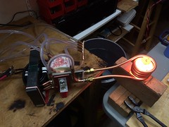
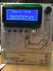
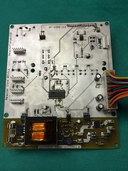
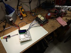
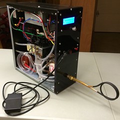
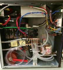
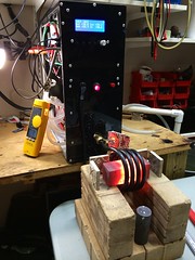
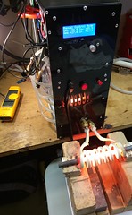
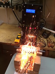
Josh Campbell, Thu Feb 05 2015, 10:14PM
Robert2 wrote ...
Good Day Josh Campbell !
I have a few questions for you.
1. Why do you don't use DC blocking cap on out fullbridge?
2. Why use two different types of ferrite cores?
3. What will change increase / decrease the working coil diameter of the pipe?
4. I know it will change the inductance and fo. The smaller diameter of the pipe is greater resistance and losses. You currently use a pipe with a diameter of 10mm I think. Typically, when used under 10-15KW pipe with a diameter of 6mm. What benefits can result from the use of smaller diameter pipes?
5. Is the cooling of a capacitor is sufficient?
6. Where you bought these capacitors?
7. Do not heat up the housing elements?
- The second and third prototypes did not have DC blocking caps however the current version does use capacitive coupling between the bridge and matching transformer.
As you know a DC blocking capacitor should behave like a short at working frequency. Calculate the reactance in ohms of the DC blocking capacitor for a minimum value at your working frequency, Xc(ohms) = 1/(2 x 3.14 x f x C). The reactance should be less than 2 ohms at working frequency, which is around 40-60Khz in my current setup. You also need to pay attention to the self resonance frequency of the capacitor and ensure that the capacitance does not react with the inductance of the primary in the matching transformer in an undesirable way. - I think what you are referring to is the old toroidal cores used in my earlier setup, I just used what I had on hand. I was saturating the core so I added more of a different type. I'm now using a large type 3C85 E core.
- It will have a very small effect on inductance and f(o), the bigger issue will be cooling if you go smaller.
- The current sizes I'm using on working coils are 1/4" (6.35mm) and 3/8"(9.525mm). The smaller tube offers higher turn count in a smaller area which allows for higher L, lower f(o) and concentration of those parameters in a smaller area, desirable in some setups.
- In the old setup the caps got warm operating at 100% but never overheated. The new setup uses Celem water cooled caps, zero thermal issues at 100%.
- The old euro-farad caps are from eBay, the new Celem are direct from Celem in Israel.
- Yes actually the housing did head up in the old version a bit due to all the parasitic inductance. The new setup with the better matching transformer contains the field much better and has a very low amount of parasitic inducuance.
Here's a video and a few photos of the current setup. I'm working on getting all the specs and build details put together to make this available on this forum and on the Github project repository.


Re: Induction Heater - Series Resonant - uC/PLL Tuning [ReactorForge]
Robert2, Fri Feb 06 2015, 08:09PM
Thank you very much for your extensive reply.
Why do not I see in you any large capacitors in the power supply of the bridge ? Have followed two large ferrite transformer . This material 3C85 , wrote that this type of E. It seems to me that I see C- cores or UI or L. What did you use the size of the core ? How many turns of the primary winding is ? What power has the final version of the photos , the core ? I am planning heater power of 15KW , I wanted to use the TX58 core 8-10 , 3E25 material
Even considering buying the core :

F887 material .
Considering also connected to the 4 sets of cores E80 / 38 / 20-3C90 or two sets of U93 / 76 / 30-3C90

Induction heater will operate at a frequency of ~ 80kHz . Are you able to help me choose which of the available cores that you have presented , and specify the number of sets ? The heater is working with graphite crucible
Robert2, Fri Feb 06 2015, 08:09PM
Thank you very much for your extensive reply.
Why do not I see in you any large capacitors in the power supply of the bridge ? Have followed two large ferrite transformer . This material 3C85 , wrote that this type of E. It seems to me that I see C- cores or UI or L. What did you use the size of the core ? How many turns of the primary winding is ? What power has the final version of the photos , the core ? I am planning heater power of 15KW , I wanted to use the TX58 core 8-10 , 3E25 material

Even considering buying the core :

F887 material .
Considering also connected to the 4 sets of cores E80 / 38 / 20-3C90 or two sets of U93 / 76 / 30-3C90

Induction heater will operate at a frequency of ~ 80kHz . Are you able to help me choose which of the available cores that you have presented , and specify the number of sets ? The heater is working with graphite crucible
Re: Induction Heater - Series Resonant - uC/PLL Tuning [ReactorForge]
Josh Campbell, Fri Feb 06 2015, 09:41PM
Rough UI dimensions.

Planned core type E/I configuration.
Some helpfull core calculators.
Josh Campbell, Fri Feb 06 2015, 09:41PM
Robert2 wrote ...
1. Why do not I see in you any large capacitors in the power supply of the bridge?
2. Have followed two large ferrite transformer. This material 3C85 , wrote that this type of E. It seems to me that I see C- cores or UI or L. 3. What did you use the size of the core ?
4. How many turns of the primary winding is ?
5. What power has the final version of the photos , the core ?
6. I am planning heater power of 15KW
7. I wanted to use the TX58 core 8-10 , 3E25 material

- There are no filter capacitors, the DC supply is unfiltered. At higher power levels this has some important benefits. (low PF, low reactive power, less RFI)
- In these photos I'm still using the dual UI cores in an EI configuration. Total AL = 6800
- See image below for dimensions.
- Primary = 12 turns (Secondary = 1 turn x 4 conductors)
- The unit shown can run on single phase 240V drawing 90A (100A breaker) with robust cooling. I limit it in software to about 65A peek input current and find that a modest 30-35A is plenty to heat typical applications with ease and speed.
- 15KW of input power? Are you counting reactive power in that total?
- 3E25 is made for EMI suppression, although it will likely work it has a sharp drop off in permeability at about 140ºC. The Ferroxcube 3C90 material or similar is ideal for this power application.
Rough UI dimensions.

Planned core type E/I configuration.
Some helpfull core calculators.
Re: Induction Heater - Series Resonant - uC/PLL Tuning [ReactorForge]
Robert2, Sat Feb 07 2015, 07:51AM
Thank you again for your reply. Sometimes it happens that someone does not answer. I am very grateful for your answers.
I want to get the output power of 15KW, induction heater is designed for the early melting of silver in a graphite crucible. In my country, it is not possible to use a single phase power supply with such a large current. The solution is 3x380VAC three phases. I want to use the bridge rectifier, the output will be around 550VDC.
1. How do you adjust the power? You are using a thyristor or SRC to adjust? I think about the power control using the phase shift.
2. You say that you set the maximum input current of the controller. Conclude that the feedback is performed by measuring current flow bridge? Now, however, I noticed that there are two current transformers.
I intend to use high-speed IGBTs, 2MBI200NB-120 PDF
Already predicted to cooling water block.
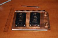
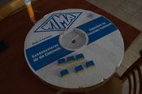
The makings of a resonant capacitor WIMA FKP-1. 4,6uF Ultimately, it will be 140 pieces of capacitors, mounted on copper flat bar. They will use the fan cooling section. Capacitors Act so that they are between spacing and air can heat away
Robert2, Sat Feb 07 2015, 07:51AM
Thank you again for your reply. Sometimes it happens that someone does not answer. I am very grateful for your answers.
I want to get the output power of 15KW, induction heater is designed for the early melting of silver in a graphite crucible. In my country, it is not possible to use a single phase power supply with such a large current. The solution is 3x380VAC three phases. I want to use the bridge rectifier, the output will be around 550VDC.
1. How do you adjust the power? You are using a thyristor or SRC to adjust? I think about the power control using the phase shift.
2. You say that you set the maximum input current of the controller. Conclude that the feedback is performed by measuring current flow bridge? Now, however, I noticed that there are two current transformers.
I intend to use high-speed IGBTs, 2MBI200NB-120 PDF

Already predicted to cooling water block.


The makings of a resonant capacitor WIMA FKP-1. 4,6uF Ultimately, it will be 140 pieces of capacitors, mounted on copper flat bar. They will use the fan cooling section. Capacitors Act so that they are between spacing and air can heat away

Re: Induction Heater - Series Resonant - uC/PLL Tuning [ReactorForge]
Ramonn, Thu Feb 19 2015, 10:12PM
...
Ramonn, Thu Feb 19 2015, 10:12PM
...
Re: Induction Heater - Series Resonant - uC/PLL Tuning [ReactorForge]
parasole, Wed Mar 25 2015, 03:34PM
Hi Josh,
any chance for updates on GitHub/ReactorForge?
parasole, Wed Mar 25 2015, 03:34PM
Hi Josh,
any chance for updates on GitHub/ReactorForge?
Re: Induction Heater - Series Resonant - uC/PLL Tuning [ReactorForge]
Josh Campbell, Sat Dec 16 2017, 08:03PM
Yes.
You can also follow the blog for updates or posts on Patreon. I will continue to update this forum thread as well. Although at some point I might make a new thread, to separate the older models (Prototypes, MKI, II, etc.) from the new ReactorForge types.
Josh Campbell, Sat Dec 16 2017, 08:03PM
Ramonn wrote ...
...
...
parasole wrote ...
Hi Josh,
any chance for updates on GitHub/ReactorForge?
Hi Josh,
any chance for updates on GitHub/ReactorForge?
Yes.

You can also follow the blog for updates or posts on Patreon. I will continue to update this forum thread as well. Although at some point I might make a new thread, to separate the older models (Prototypes, MKI, II, etc.) from the new ReactorForge types.
Print this page