If you need assistance, please send an email to forum at 4hv dot org. To ensure your email is not marked as spam, please include the phrase "4hv help" in the subject line. You can also find assistance via IRC, at irc.shadowworld.net, room #hvcomm.
Support 4hv.org!
Donate:
4hv.org is hosted on a dedicated server. Unfortunately, this server costs and we rely on the help of site members to keep 4hv.org running. Please consider donating. We will place your name on the thanks list and you'll be helping to keep 4hv.org alive and free for everyone. Members whose names appear in red bold have donated recently. Green bold denotes those who have recently donated to keep the server carbon neutral.
Special Thanks To:
Aaron Holmes
Aaron Wheeler
Adam Horden
Alan Scrimgeour
Andre
Andrew Haynes
Anonymous000
asabase
Austin Weil
barney
Barry
Bert Hickman
Bill Kukowski
Blitzorn
Brandon Paradelas
Bruce Bowling
BubeeMike
Byong Park
Cesiumsponge
Chris F.
Chris Hooper
Corey Worthington
Derek Woodroffe
Dalus
Dan Strother
Daniel Davis
Daniel Uhrenholt
datasheetarchive
Dave Billington
Dave Marshall
David F.
Dennis Rogers
drelectrix
Dr. John Gudenas
Dr. Spark
E.TexasTesla
eastvoltresearch
Eirik Taylor
Erik Dyakov
Erlend^SE
Finn Hammer
Firebug24k
GalliumMan
Gary Peterson
George Slade
GhostNull
Gordon Mcknight
Graham Armitage
Grant
GreySoul
Henry H
IamSmooth
In memory of Leo Powning
Jacob Cash
James Howells
James Pawson
Jeff Greenfield
Jeff Thomas
Jesse Frost
Jim Mitchell
jlr134
Joe Mastroianni
John Forcina
John Oberg
John Willcutt
Jon Newcomb
klugesmith
Leslie Wright
Lutz Hoffman
Mads Barnkob
Martin King
Mats Karlsson
Matt Gibson
Matthew Guidry
mbd
Michael D'Angelo
Mikkel
mileswaldron
mister_rf
Neil Foster
Nick de Smith
Nick Soroka
nicklenorp
Nik
Norman Stanley
Patrick Coleman
Paul Brodie
Paul Jordan
Paul Montgomery
Ped
Peter Krogen
Peter Terren
PhilGood
Richard Feldman
Robert Bush
Royce Bailey
Scott Fusare
Scott Newman
smiffy
Stella
Steven Busic
Steve Conner
Steve Jones
Steve Ward
Sulaiman
Thomas Coyle
Thomas A. Wallace
Thomas W
Timo
Torch
Ulf Jonsson
vasil
Vaxian
vladi mazzilli
wastehl
Weston
William Kim
William N.
William Stehl
Wesley Venis
The aforementioned have contributed financially to the continuing triumph of 4hv.org. They are deserving of my most heartfelt thanks.
Registered Member #1143
Joined: Sun Nov 25 2007, 04:55PM
Location: Vilnius, Lithuania
Posts: 721
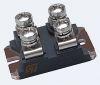
Ok, here is the deal, I need to melt some material (magnetic) and reach 2500C. so I guess I will need more than 10kW for this to happen. So I have got 3x SKM200GB125D and one for the final version SKM400GB125D
+-12V power supply for a +-24V Gate driver with 2:1:1 ratio
Here is resonant controller which doesn't work as I would like, a lot of noise and it even doesn’t work as it should. controller is MC33067
Capacitor bank for bridge power supply 3phase capable with middle point for matching transformer
IGBT GDT driver is made from Full-bridge IRFZ34N iRF9Z34N mosfet's and TC4422 drivers.
LC have 30kHz Fo , with 12.25uF 450A (+ Celem 1uF 550A 500V) capacitor bank sandwiched with two 5mm copper plates.
water cooled coil, noting very interesting 6mm diameter
For galvanic insulation I will use a matching transformer which is also capable to reach around 30kW (from CT scanner flyback transformer)
3 Phase rectifier for the final version (60KW capable rectifier)
Uge looks like this, and I am quite happy with that (later I can change it to +-15V )
I have a few questions: Should I use parallel LC circuit or in series? And what kind of driver should I use? I need only power control
Registered Member #30
Joined: Fri Feb 03 2006, 10:52AM
Location: Glasgow, Scotland
Posts: 6706
Looks good! :)
Linas wrote ...
LC have 30kHz Fo , with 12.25uF 450A (+ Celem 1uF 550A 500V) capacitor bank sandwiched with two 5mm copper plates.
It looks like you've used ordinary steel bolts to mount the capacitors. They may get very hot especially if the RF current is allowed to flow through them. I used brass bolts for my IH tank circuit.
However, I've used steel bolts for connections in Tesla coil tank circuits, and it seems to work provided the bolts are just clamping a direct copper-to-copper contact.
The LCLR and series-feed tank circuits behave quite similarly from a drive point of view.
Registered Member #1143
Joined: Sun Nov 25 2007, 04:55PM
Location: Vilnius, Lithuania
Posts: 721
Steve Conner wrote ...
Looks good! :)
However, I've used steel bolts for connections in Tesla coil tank circuits, and it seems to work provided the bolts are just clamping a direct copper-to-copper contact.
The LCLR and series-feed tank circuits behave quite similarly from a drive point of view.
Yes, they just clamp massive brass plates to copper ones. My question is, if I want to melt steel, I need to use current or voltage LC circuit? The only reason I think of putting in series, is that they can use more from HV capacitors, and since I have quite a low voltage I should use a parallel LC circuit Or is it something i don't know? Which circuit is most suitable for melting steel? For now, I will try to fix my MC33067 current feedback controller
Registered Member #2919
Joined: Fri Jun 11 2010, 06:30PM
Location: Cambridge, MA
Posts: 652
I've used steel bolts in my IH with no ill effects. Since you're using a transformer, you can safely use a series-fed topology, since the transformer can perform impedance matching between the tank and the inverter. A simple way to control power is simply to detune the driver. This works, but is lossy. Alternatively, you could try a thyristor-based rectifier feeding the bus, and just modulate the bs voltage. Oh, and nice Celem, BTW :)
Registered Member #1143
Joined: Sun Nov 25 2007, 04:55PM
Location: Vilnius, Lithuania
Posts: 721
bwang wrote ...
A simple way to control power is simply to detune the driver. This works, but is lossy. Alternatively, you could try a thyristor-based rectifier feeding the bus, and just modulate the bs voltage. Oh, and nice Celem, BTW :)
Yes, MC33067 works that way, it goes to into higher side from Fo, and it keeps zero voltage switching as well, so no loss here ( as far as I understand or is it just at max power, i don't know) and best thing, it has 0 phase difference since it doesn't use any feedback for oscillation whatsoever Here is the problem MC33067 is set up to limit 60kHz and with a current control oscillator and a 25k resistor gives 21kHz oscillation frequency to an error amplifier output when E/A is low (a high one gives 60kHz oscillation frequency) Problem is, that the current limiter doesn't work, when I turn on the power very low , it jumps to 60kHz, and if I set just a bit more the oscillation goes to 21kHz, and I can't get anything in between. Here is the principal circuit of MC33067:
and here is my feedback part:
I use bleed resistor after 1N5819 rectifier so I don't have to deal with Vf CT set to 10A/V so I should limit the power at 51A with my Vref which is 5.1V
Brass , aluminum, steel Steel washer just cut my crucible in half so I have to stop melting. it's only 1/5 of the original power :) and here is problem with CCO
Registered Member #1143
Joined: Sun Nov 25 2007, 04:55PM
Location: Vilnius, Lithuania
Posts: 721
still stuck with feedback problem, can't get it working on MC33067, clearly enough i get same problem with PLL driver If some one point out problem so my feedback will run as i would and clear power regulation via CT and current set potentiometer is achieved, i can donate Celem cap for that person
Right now problem is that low power regulation is working, and getting closer and closer to Fo i get lot of noise and eventually it jumps below Fo,
Bridge is solid, can deal with 220V ,blowing 16A fuses with no sweat
Registered Member #30
Joined: Fri Feb 03 2006, 10:52AM
Location: Glasgow, Scotland
Posts: 6706
If you ever allow the frequency to get close to f0, it is likely to fall under f0, at which point it will get stuck at the lowest frequency. This is because the feedback in the current control loop changes sign and becomes positive below f0. At f0 itself the loop gain is zero, and I think this is why you see the noise.
The solution (IMO) is to increase the lower frequency limit so it is above f0 under all conditions, and increase the DC bus voltage until you get your desired power level.
You can also run in the leading region below f0 by swapping the terminals on the error amp and resetting the limits. IGBTs may run more efficiently in this mode.
Registered Member #1143
Joined: Sun Nov 25 2007, 04:55PM
Location: Vilnius, Lithuania
Posts: 721
good idea, i can try that. below resonance i get a little bit of noise but its around 5-10% bus voltage. But in that operation i will have hard switching , not so good update
Registered Member #146
Joined: Sun Feb 12 2006, 04:21AM
Location: Austin Tx
Posts: 1055
So i think the problem is with your current feedback circuit. The RC time constant of 30 ohms and 1nF is only 30nS, so this is not effectively filtering. After this you have 1k and 330pF, only a 330nS time constant, again very fast compared to the 20-60khz signals you are trying to average and regulate.
You could either 1) insert another diode (and incur its forward drop) after the burden resistor so that you just capture the peak, and feed it into a much larger RC filter, or 2) make your capacitors way bigger in the existing circuit to achieve a smoother averaged signal.
I think your regulator must be going crazy trying to keep up with a feedback signal with so much ripple.
EDIT:
After looking at your error amp circuit some more, i have some questions. Is the E/A amp a voltage to current amp? If you used a regular voltage type op amp, it looks like it would just behave like a comparator.
Another thing im not clear on is how the error amp drives the frequency. Right now it looks like it starts out at a high frequency and then drops the frequency as the current reaches the target level. This would be the opposite of the control i would employ, which is to have the controller default to Fres, and have the frequency increase as the current reached the target level. This increase in frequency should provide inductive switching for the inverter, which i believe is preferred over capacitive load switching.
This site is powered by e107, which is released under the GNU GPL License. All work on this site, except where otherwise noted, is licensed under a Creative Commons Attribution-ShareAlike 2.5 License. By submitting any information to this site, you agree that anything submitted will be so licensed. Please read our Disclaimer and Policies page for information on your rights and responsibilities regarding this site.


 +10KW induction heater