
DIY High voltage probe
radhoo, Mon Nov 29 2010, 06:43PMMotivation/Short Intro
For my High voltage experiments, knowing the exact potential difference of a given supply value would be extremely useful. So I decided to build a high voltage probe, using a resistive divider. After doing some calculations, I decided to go for a 1:1000 divider ratio, for the many advantages including ease of reading the measured values (10kV -> 10V).


The High voltage goes as Vin, and the measurement is done at Vout.
I needed a 1GOhm resistor, so I purchased 5x 200MO Vishay Dale High voltage resistors from Ebay. Connecting them in series I get the desired value:


To insulate this resistor, I put it in a PVC pipe under oil:


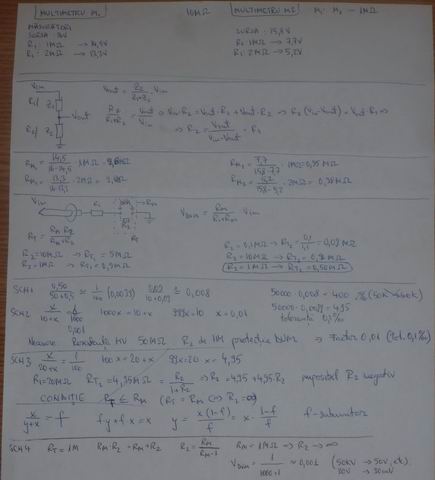
If R1 is 1GOhm, and R2 is 1MOhm, the voltage drop across R2 , Vout will be aprox. 1/1000 * Vin . Instead of R2 I use a multimeter with 1MOhm impedance (However, to protect the multimeter, additional components are required). The results:


The left picture shows a good result: for 30.3V in, the multimeter measures 32mA, very close to the 1/1000 ratio (actually the ratio is 1/1001).
Use the probe for HV
Exactly as Proud Mary suggested, I had to "throw away" the multimeter, and get a good old analog microAmpmeter.
-to be continued-
Old issues - fixed - please read the entire thread
However, trying to use this probe with my 50KV cascade supply, gives very poor results. The multimeter jumps between values, the biggest shown is 12 (12KV). Probably because of the high frequency currents.
Any idea on what am I missing? Do I need a capacitive divider? Do I need a combination of the two? Thanks.
Re: DIY High voltage probe
Proud Mary, Mon Nov 29 2010, 07:20PM
Your '50kV cascade' supply seems to be a Cockcroft & Walton voltage multiplier, which has a DC output.
A voltage divider measurement network is suitable for use in DC and low frequency AC measurements, so this is not your problem.
Saying that your multimeter has an input impedance - Z - of 1M, is not at all the same as thinking of the meter as a simple 1M resistance - R - across the terminals. This is your problem, Radhu.
What will be a big problem is if your meter goes open circuit - when 50kV will appear at the bottom end of your 1G resistor.
Here is what you must do: throw away the meter with 1M input impedance and buy another with the standard Zin = 10M.
Connect a resistor of 1M1 from the bottom of the 1G resistor and the Earth. (Connect a neon or zener across this resistor for safety) Measure the voltage across this with your 10M input impedance meter and all will be well.
Avram Iancu - pehblendã / oxid de uraniu nativ
Re: DIY High voltage probe
radhoo, Mon Nov 29 2010, 09:35PM
Thanks for your reply and suggestions! I'll try to do the mods tomorrow and hope for better results.
Initially I planned to use two resistors R1-1GO and R2-1MO as per the schematics above. However I quickly learned that the multimeter's impedance will change the results. That's why I excluded R2 and simply used the multiplier with it's internal 1MO impedance. I would really need some clarification on why it works like this, when testing with a small voltage supply even if I'm mixing things (Rs with Zs)
I do have a better multimeter with 10MO impedance, and other features, but I don't want to put that anywhere close to the 50KV supply. I also have a digital 1MO impedance multimeter that I was planning to embed into this probe. Why do you think it is a must to use a 10MO multimeter?
About the Zener and the Neon: indeed a most welcomed protection, I already tried paralleling a Neon over the Multimeter's terminals but it was changing the measurements. I've seen this while testing the "probe" with small voltages. Probably my mistake, will try that again (since a neon glass lamp should be somewhere close to 200GO?)
"Avram Iancu - pehblendã / oxid de uraniu nativ"
Thanks for mentioning Avram Iancu over "Dracula" . Much appreciated.
Re: DIY High voltage probe
Proud Mary, Mon Nov 29 2010, 09:57PM
Think of your two resistors in series: 1000M and 1M - a simple ratio of 1000:1.
Now, if I take a second resistor of 1M, and connect that in parallel with the first resistor of 1M, we have a resistance of 1/R = 1/R1 + 1/R2 which is 0.5M - 500K.
So we have a ratio of 1000M/0.5 = 2000:1 by using your 1M meter, which will be completely incorrect!
Now, if you take a 10M resistor (think of your meter), and connect that in parallel with your 1M, we have a combined resistance of 910K - so here your voltage divider would have a ratio of 1000:0.95 - no good to us!
But if we make the bottom resistor in the potential divider 1.111Meg-ohms (or 1M111 as we write it) we find that when we put this in parallel with your 10M resistor we have exactly 1M - and the 1000:1 ratio has been preserved! For all ordinary purposes, you can use a resistor of 1M1 as the bottom resistor, which we call the measuring resistor in this circuit.
Klar?
Proud Mary, Mon Nov 29 2010, 09:57PM
radhoo wrote ...
Thanks for your reply and suggestions! I'll try to do the mods tomorrow and hope for better results.
Initially I planned to use two resistors R1-1GO and R2-1MO as per the schematics above. However I quickly learned that the multimeter's impedance will change the results. That's why I excluded R2 and simply used the multiplier with it's internal 1MO impedance. I would really need some clarification on why it works like this, when testing with a small voltage supply even if I'm mixing things (Rs with Zs)
I do have a better multimeter with 10MO impedance, and other features, but I don't want to put that anywhere close to the 50KV supply. I also have a digital 1MO impedance multimeter that I was planning to embed into this probe. Why do you think it is a must to use a 10MO multimeter?
About the Zener and the Neon: indeed a most welcomed protection, I already tried paralleling a Neon over the Multimeter's terminals but it was changing the measurements. I've seen this while testing the "probe" with small voltages. Probably my mistake, will try that again (since a neon glass lamp should be somewhere close to 200GO?)
"Avram Iancu - pehblendã / oxid de uraniu nativ"
Thanks for mentioning Avram Iancu over "Dracula" . Much appreciated.
Think of your two resistors in series: 1000M and 1M - a simple ratio of 1000:1.
Now, if I take a second resistor of 1M, and connect that in parallel with the first resistor of 1M, we have a resistance of 1/R = 1/R1 + 1/R2 which is 0.5M - 500K.
So we have a ratio of 1000M/0.5 = 2000:1 by using your 1M meter, which will be completely incorrect!
Now, if you take a 10M resistor (think of your meter), and connect that in parallel with your 1M, we have a combined resistance of 910K - so here your voltage divider would have a ratio of 1000:0.95 - no good to us!
But if we make the bottom resistor in the potential divider 1.111Meg-ohms (or 1M111 as we write it) we find that when we put this in parallel with your 10M resistor we have exactly 1M - and the 1000:1 ratio has been preserved! For all ordinary purposes, you can use a resistor of 1M1 as the bottom resistor, which we call the measuring resistor in this circuit.
Klar?
Re: DIY High voltage probe
radhoo, Tue Nov 30 2010, 09:23AM
yes, thanks for the examples, I did most of these scenarios on a piece of paper, however I still don't understand why the divider works without using R2, relying only on the multimeter's impedance (which is 1M):
Taking this another example:

The author speaks about R3, the internal resistance of the DMM. Before picking my multimeter I did some measurements like: Known voltage supply, measured by the multimeter in series with a 1MO resistor (, where resulted that my multimeter can work in a divider as a factor of 1MO.
Moving further, since I still have the question of impedance vs. resistance (unfortunately I did a different school), I see the following on Wiki:
Electrical impedance, or simply impedance, describes a measure of opposition to alternating current (AC). Electrical impedance extends the concept of resistance to AC circuits, describing not only the relative amplitudes of the voltage and current, but also the relative phases. When the circuit is driven with direct current (DC) there is no distinction between impedance and resistance; the latter can be thought of as impedance with zero phase angle.
All my tests have been performed in DC (except measuring the 50KV supply that may still show some ripple), so the 1MO impedance multimeter performed as a 1MO resistor. So this is the answer to my question.
On repairfaq, the author further says:
While R2 is not strictly needed, it is recommended that it be included and approximately equal to the Z-in of the meter on the scale you will be using. The reason to include R2 is to insure that high voltage never can reach the meter.
I've seen this article before building my probe and probably this was another reason I dropped the resistor relying only on the multimeter's resistance.
However now I'm back to the start. Why doesn't this work?
radhoo, Tue Nov 30 2010, 09:23AM
yes, thanks for the examples, I did most of these scenarios on a piece of paper, however I still don't understand why the divider works without using R2, relying only on the multimeter's impedance (which is 1M):
Taking this another example:
The author speaks about R3, the internal resistance of the DMM. Before picking my multimeter I did some measurements like: Known voltage supply, measured by the multimeter in series with a 1MO resistor (
 "Link2") , where resulted that my multimeter can work in a divider as a factor of 1MO.
, where resulted that my multimeter can work in a divider as a factor of 1MO.Moving further, since I still have the question of impedance vs. resistance (unfortunately I did a different school), I see the following on Wiki:
Electrical impedance, or simply impedance, describes a measure of opposition to alternating current (AC). Electrical impedance extends the concept of resistance to AC circuits, describing not only the relative amplitudes of the voltage and current, but also the relative phases. When the circuit is driven with direct current (DC) there is no distinction between impedance and resistance; the latter can be thought of as impedance with zero phase angle.
All my tests have been performed in DC (except measuring the 50KV supply that may still show some ripple), so the 1MO impedance multimeter performed as a 1MO resistor. So this is the answer to my question.
On repairfaq, the author further says:
While R2 is not strictly needed, it is recommended that it be included and approximately equal to the Z-in of the meter on the scale you will be using. The reason to include R2 is to insure that high voltage never can reach the meter.
I've seen this article before building my probe and probably this was another reason I dropped the resistor relying only on the multimeter's resistance.
However now I'm back to the start. Why doesn't this work?
Re: DIY High voltage probe
Proud Mary, Tue Nov 30 2010, 10:49AM
Here is what to do.
Buy an old Russian moving coil 50μA panel meter and use this in series with your 1G resistor. You will have 50μA= 50kV. End of story.

For safety's sake, you should connect a small neon bulb and a zener in parallel with the meter, so that if the meter fails and becomes open circuit - a very rare event, but possible - then the neon and zener will conduct away high voltage appearing at the end of the 1G resistor. If the zener should also fail, the neon will start to conduct.
Re: DIY High voltage probe
radhoo, Tue Nov 30 2010, 01:11PM
Thanks Proud Mary, for bearing with me on this one and for the practical advise, I'll look around for an old uA meter, but while I do that, I'm still intrigued about the poor results in my first attempt, using the DVM.
I need to understand the failure reasons. Did you (or others on the forum) perhaps tried to build a probe and maybe have a clue on this?
Re: DIY High voltage probe
Proud Mary, Tue Nov 30 2010, 01:23PM
I think it's because the DMM input has some active devices in it - it's not just a resistance going straight to Earth - and perhaps the DC is 'dirty' with switching waveforms imposed upon it. I'd guess that if you used your C&W 'cascade' to charge a capacitor - say a Leyden Jar - and then measured the voltage across that, it would work properly. But do be careful if you try this, or you will be toast, my friend!
Proud Mary, Tue Nov 30 2010, 01:23PM
radhoo wrote ...
Thanks Proud Mary, for bearing with me on this one and for the practical advise, I'll look around for an old uA meter, but while I do that, I'm still intrigued about the poor results in my first attempt, using the DVM.
I need to understand the failure reasons. Did you (or others on the forum) perhaps tried to build a probe and maybe have a clue on this?
I think it's because the DMM input has some active devices in it - it's not just a resistance going straight to Earth - and perhaps the DC is 'dirty' with switching waveforms imposed upon it. I'd guess that if you used your C&W 'cascade' to charge a capacitor - say a Leyden Jar - and then measured the voltage across that, it would work properly. But do be careful if you try this, or you will be toast, my friend!
Re: DIY High voltage probe
Patrick, Tue Nov 30 2010, 02:52PM
what material is the cork stuff in the ends of your oil filled pipe? how did you get a good leak proof seal?
Patrick, Tue Nov 30 2010, 02:52PM
what material is the cork stuff in the ends of your oil filled pipe? how did you get a good leak proof seal?
Re: DIY High voltage probe
radhoo, Tue Nov 30 2010, 03:04PM
it's hot glue.
The first end (with the pipe empty of oil) was simply sealed with a perfectly matching cylinder of glue bar, and the resistor's connector inserted though it. Additional hot glue was added to ensure sealing.
The other end could not take a sealing bar since the air inside would have been compressed. So I carefully sealed it with hot glue, directly over the oil's surface. Not even one bubble of air left.
Re: DIY High voltage probe
Patrick, Tue Nov 30 2010, 05:38PM
are you sure these resistors are non-inductive?
Patrick, Tue Nov 30 2010, 05:38PM
radhoo wrote ...
However, trying to use this probe with my 50KV cascade supply, gives very poor results. The multimeter jumps between values, the biggest shown is 12 (12KV). Probably because of the high frequency currents.
Any idea on what am I missing? Do I need a capacitive divider? Do I need a combination of the two? Thanks.
are you sure these resistors are non-inductive?
Re: DIY High voltage probe
Patrick, Thu Dec 02 2010, 05:40PM
im worried the resistors you and i bought are inductive to some degree, thats why your getting jumpy and bogus numbers with your 50kV CW.
Patrick, Thu Dec 02 2010, 05:40PM
im worried the resistors you and i bought are inductive to some degree, thats why your getting jumpy and bogus numbers with your 50kV CW.
Re: DIY High voltage probe
Proud Mary, Thu Dec 02 2010, 05:52PM
Surely the C&W output is DC so the inductance of the resistors shouldn't be an issue after a brief settling time - unless perhaps there is a bad ripple floating on top of it, as I suggested above.
Proud Mary, Thu Dec 02 2010, 05:52PM
Patrick wrote ...
im worried the resistors you and i bought are inductive to some degree, thats why your getting jumpy and bogus numbers with your 50kV CW.
im worried the resistors you and i bought are inductive to some degree, thats why your getting jumpy and bogus numbers with your 50kV CW.
Surely the C&W output is DC so the inductance of the resistors shouldn't be an issue after a brief settling time - unless perhaps there is a bad ripple floating on top of it, as I suggested above.
Re: DIY High voltage probe
Patrick, Fri Dec 03 2010, 04:07AM
i asummed bad ripple and higher then 60Hz operation... when i warned of possible inductance.
EDIT: he was driving his CW with a ZVS so i can assume the freq is significant, Proud Mary.
EDIT: i believe if there is not a "N" in the part mark, then they are inductive. dam it.
here is the PDF, for Vishay/Dale ROX: (look at the ROX 1-1/2 line)
]rox.pdf[/file]

I read Part mark as: DALE ROX-1-1/2S 200M0 FK 0950 the 09 is year the 50 is the week, i think.
i wonder if used in series, in even numbers, if the resistors can be arranged in counter-turn-series, to cancel the inductance.
here is the original package and label, MINE ARRIVED TODAY...YAY!

ROX150 200M FKLBS -- 11kV resistors
"FKLBS" suffix is defined as :
-- Tolerance +-1%
-- TCo, 100ppm
-- Tin/Pb, Lacer
-- Solid Body, Axial, AL2O3
They are definately inductive. and thats a problem.
Re: DIY High voltage probe
Patrick, Fri Dec 03 2010, 08:25AM
i will make capacitience measurements soon in pipe-oil-shield configuration.
Patrick, Fri Dec 03 2010, 08:25AM
i will make capacitience measurements soon in pipe-oil-shield configuration.
Re: DIY High voltage probe
radhoo, Fri Dec 03 2010, 09:50AM
Here's the resistive/capacitive divider from the Glassman supply:
You can see the resistors used. Probably this would be a better approach.
radhoo, Fri Dec 03 2010, 09:50AM
Here's the resistive/capacitive divider from the Glassman supply:
You can see the resistors used. Probably this would be a better approach.
Re: DIY High voltage probe
Patrick, Fri Dec 03 2010, 09:57AM
yes but with "rdb" in series with the C bandwidth will be poor.
Patrick, Fri Dec 03 2010, 09:57AM
radhoo wrote ...
Here's the resistive/capacitive divider from the Glassman supply:
You can see the resistors used. Probably this would be a better approach.
Here's the resistive/capacitive divider from the Glassman supply:
You can see the resistors used. Probably this would be a better approach.
yes but with "rdb" in series with the C bandwidth will be poor.
Re: DIY High voltage probe
Steve Conner, Fri Dec 03 2010, 12:11PM
I think those rdb's are to stop the measuring circuit being taken out instantly by an arc to ground, which would discharge the whole series string of capacitors through it.
Same as the resistors in series with the diodes, they protect the diodes from ground arcs.
Re: DIY High voltage probe
Pinky's Brain, Fri Dec 03 2010, 02:48PM
With appropriately chosen values your oscillograph can record accurate waveforms :)
Pinky's Brain, Fri Dec 03 2010, 02:48PM
Patrick wrote ...
yes but with "rdb" in series with the C bandwidth will be poor.
So reduce rdb (as well as the capacitors). The advantage of RC series strings is that the resistors damp the internal oscillations.yes but with "rdb" in series with the C bandwidth will be poor.
With appropriately chosen values your oscillograph can record accurate waveforms :)
Re: DIY High voltage probe
Patrick, Fri Dec 03 2010, 10:32PM
yep, thats my plan.
Patrick, Fri Dec 03 2010, 10:32PM
yep, thats my plan.
Re: DIY High voltage probe
..., Sat Dec 04 2010, 07:52AM
There is no reason that your probe should not work well when measuring a DC voltage, such as is present on a correctly functioning CW multiplier.
From this you can conclude that either your multiplier is not working properly (and it outputting a large AC component), or that you are getting some type of internal corona/sparking loss in your probe.
One experiment to try-connect a capacitor across the output of the CW (if you have access to doorknob caps a few in series would work well, if not you may need to resort to something like a glass parallel plate capacitor of a few nf) and charge it up with the CW. You can then be sure that the output is a pure DC, and your measurements will be correct.
Furthermore, while it is sketchy business connecting a 1Gohm resistor directly in series with a voltmeter, there is no reason that the impedance of your voltmeter should vary significantly from 1Mohm. Most digital voltmeters internally have a very high input impedance (into the Gohm range), and have a resistor in parallel with the output so that stray charge does not cause false readings--and to insure the meter has a constant known input impedance for applications such as this. If you want to be sure, measure the input impedance using your nice voltmeter, you should find it reads quite close to 1Mohm. The neon bulb across the input is a good idea, as is making sure that you have the other side of the bulb well grounded to something that is known to be ground--not simply the negative of a power supply/voltmeter.
Re: DIY High voltage probe
Steve Conner, Sat Dec 04 2010, 03:31PM
+1, except that DMMs don't have a constant known input impedance. It's not unknown for it to vary with the range. If it does then it's usually extremely high (100M? 1G? Not sure) on the lowest DC voltage range and 11M Ohms on all the higher ones.
So, if your meter is autoranging while it's connected to the divider, the autoranging could go unstable. I would lock the meter to the 10V range and put a 1M resistor across it, to be sure.
Re: DIY High voltage probe
Sulaiman, Sun Dec 05 2010, 10:30AM
Although wirewound resistors do have inductance I doubt that it will be significant.
i.e. at what frequency will the inductive reactance be 1% of Rdc ?
(L=(r.n)squared/(9r+10h) etc.)
The 100 MOhm resistor in my p6015 is one long helix.
In low-voltage high-current circuits the inductance of wirewound resistors (or even wires) can be very significant.
For a large C-W/Greinacher I would use a moving coil meter with a couple of 1N4148 and a capacitor across it and a string of resistors.
For a small C-W the 50uA may be too much of a load.
Tap off one of the resistors a Gas Discharge Tube of the type used for telephone lines to a reliable 'earth'.
It's quite difficult to be completely safe at the end of a resistor string from eht. and dmms are very susceptible to emi/rfi.
Re: DIY High voltage probe
Patrick, Mon Dec 06 2010, 08:41AM
Patrick, Mon Dec 06 2010, 08:41AM
Sulaiman wrote ...
Although wirewound resistors do have inductance I doubt that it will be significant.
i.e. at what frequency will the inductive reactance be 1% of Rdc ?
(L=(r.n)squared/(9r+10h) etc.)
The 100 MOhm resistor in my p6015 is one long helix.
In low-voltage high-current circuits the inductance of wirewound resistors (or even wires) can be very significant.
For a large C-W/Greinacher I would use a moving coil meter with a couple of 1N4148 and a capacitor across it and a string of resistors.
For a small C-W the 50uA may be too much of a load.
Tap off one of the resistors a Gas Discharge Tube of the type used for telephone lines to a reliable 'earth'.
It's quite difficult to be completely safe at the end of a resistor string from eht.
Agreed.Although wirewound resistors do have inductance I doubt that it will be significant.
i.e. at what frequency will the inductive reactance be 1% of Rdc ?
(L=(r.n)squared/(9r+10h) etc.)
The 100 MOhm resistor in my p6015 is one long helix.
In low-voltage high-current circuits the inductance of wirewound resistors (or even wires) can be very significant.
For a large C-W/Greinacher I would use a moving coil meter with a couple of 1N4148 and a capacitor across it and a string of resistors.
For a small C-W the 50uA may be too much of a load.
Tap off one of the resistors a Gas Discharge Tube of the type used for telephone lines to a reliable 'earth'.
It's quite difficult to be completely safe at the end of a resistor string from eht.
Sulaiman wrote ...
and dmms are very susceptible to emi/rfi.
yes, mine have gone entirely erratic due to rfi and emi, that which is not conductivly connected, ONLY RADIATED across near distances!! and dmms are very susceptible to emi/rfi.
Re: DIY High voltage probe
Pinky's Brain, Mon Dec 06 2010, 10:45PM
Pinky's Brain, Mon Dec 06 2010, 10:45PM
Patrick wrote ...
yep, thats my plan.
How about using Nichrome wire? The precision of the resistors isn't very important, it's cheap and no need to worry about dielectric strength of the resistor housing.yep, thats my plan.
Re: DIY High voltage probe
Proud Mary, Tue Dec 07 2010, 12:03AM
Gasp!
If you were to use 34 swg nichrome wire (0.24mm) which has a typical resistance of 24.7Ω/m, you would need 40.485km to make 1MΩ!
Proud Mary, Tue Dec 07 2010, 12:03AM
Pinky's Brain wrote ...
Patrick wrote ...
yep, thats my plan.
How about using Nichrome wire? The precision of the resistors isn't very important, it's cheap and no need to worry about dielectric strength of the resistor housing.yep, thats my plan.
Gasp!
If you were to use 34 swg nichrome wire (0.24mm) which has a typical resistance of 24.7Ω/m, you would need 40.485km to make 1MΩ!
Re: DIY High voltage probe
Pinky's Brain, Tue Dec 07 2010, 12:24AM
No, I meant for a RC series divider ... here the resistance values are small.
Pinky's Brain, Tue Dec 07 2010, 12:24AM
No, I meant for a RC series divider ... here the resistance values are small.
Re: DIY High voltage probe
Patrick, Tue Dec 07 2010, 02:20AM
Patrick, Tue Dec 07 2010, 02:20AM
Pinky's Brain wrote ...
No, I meant for a RC series divider ... here the resistance values are small.
Pinky please elaborate, I think proud mary is right!?No, I meant for a RC series divider ... here the resistance values are small.
Re: DIY High voltage probe
Pinky's Brain, Tue Dec 07 2010, 03:06AM
Sorry, thought you read that ancient paper I linked.
They put resistors in a capacitive voltage divider to damp the oscillations from self inductance (it's for very high voltages where the voltage gradients along the divider have to be air compatible).
Similar to the Glassman divider, except they tuned it for low bandwidth and put a high resistance resistor across the pair for DC balancing.
Re: DIY High voltage probe
Patrick, Tue Dec 07 2010, 04:00AM
i read that atricle but failed to realise what you meant, but i think the lenth of 50 + miles and TCo would be difficult to work around. but ill look at the math again.
Patrick, Tue Dec 07 2010, 04:00AM
i read that atricle but failed to realise what you meant, but i think the lenth of 50 + miles and TCo would be difficult to work around. but ill look at the math again.
Re: DIY High voltage probe
Pinky's Brain, Tue Dec 07 2010, 04:25AM
Lets say we have a 100 stage 1 MV divider with 1 uH self inductance with 10 nF capacitors per stage, for total capacitance of 100 pF. For critical damping the total series resistance has to be around 200 Ohm, so 2 Ohm per stage.
PS. hmm, this would be a huge load on something like a Tesla Coil though. With 100 pF per stage we would get 20 Ohm per stage ... which would in total burn 250 Watt for a 100 KHz 1 MV Tesla. Much more civilized.
Re: DIY High voltage probe
Patrick, Tue Dec 07 2010, 05:28AM
Patrick, Tue Dec 07 2010, 05:28AM
Pinky's Brain wrote ...
Lets say we have a 100 stage 1 MV divider with 1 uH self inductance with 10 nF capacitors per stage, for total capacitance of 100 pF. For critical damping the total series resistance has to be around 200 Ohm, so 2 Ohm per stage.
PS. hmm, this would be a huge load on something like a Tesla Coil though. With 100 pF per stage we would get 20 Ohm per stage ... which would burn 250 Watt for a 100 KHz 1 MV Tesla. Much more civilized.
my brain ponders that which you have said.Lets say we have a 100 stage 1 MV divider with 1 uH self inductance with 10 nF capacitors per stage, for total capacitance of 100 pF. For critical damping the total series resistance has to be around 200 Ohm, so 2 Ohm per stage.
PS. hmm, this would be a huge load on something like a Tesla Coil though. With 100 pF per stage we would get 20 Ohm per stage ... which would burn 250 Watt for a 100 KHz 1 MV Tesla. Much more civilized.
Re: DIY High voltage probe
Pinky's Brain, Wed Dec 08 2010, 03:44PM
This might not come as a surprise to anyone else ... but it surprised me.
Something I never really realized about high resistance probes until I read about it and ran some numbers. Lets say you are measuring a tesla coil and halfway along the probe the ground plane is far away but the tesla coil is close by ... the capacitively coupled voltage between the middle of the tesla coil and the probe will tend to overwhelm anything connected to the top for higher frequencies.
The capacitance between two 1 meter wires at 1 meter is ~3 pf ... and 1 pF at 100 KHz represents an impedance of only 10 MOhm.
Even when a high voltage source isn't nearby, the fact that the stray capacitance to ground represents a much lower impedance path than the rest of the divider will screw up the measurement (although this will just cause a high frequency fall off, which can be compensated for).
Re: DIY High voltage probe
Patrick, Wed Dec 08 2010, 05:21PM
Patrick, Wed Dec 08 2010, 05:21PM
Pinky's Brain wrote ...
This might not come as a surprise to anyone else ... but it surprised me.
Something I never really realized about high resistance probes until I read about it and ran some numbers. Lets say you are measuring a tesla coil and halfway along the probe the ground plane is far away but the tesla coil is close by ... the capacitively coupled voltage between the middle of the tesla coil and the probe will tend to overwhelm anything connected to the top for higher frequencies.
The capacitance between two 1 meter wires at 1 meter is ~3 pf ... and 1 pF at 100 KHz represents an impedance of only 10 MOhm.
Even when a high voltage source isn't nearby, the fact that the stray capacitance to ground represents a much lower impedance path than the rest of the divider will screw up the measurement (although this will just cause a high frequency fall off, which can be compensated for).
OH CRAP! i thought you realized that! other wise i would have explained it. read here : This might not come as a surprise to anyone else ... but it surprised me.
Something I never really realized about high resistance probes until I read about it and ran some numbers. Lets say you are measuring a tesla coil and halfway along the probe the ground plane is far away but the tesla coil is close by ... the capacitively coupled voltage between the middle of the tesla coil and the probe will tend to overwhelm anything connected to the top for higher frequencies.
The capacitance between two 1 meter wires at 1 meter is ~3 pf ... and 1 pF at 100 KHz represents an impedance of only 10 MOhm.
Even when a high voltage source isn't nearby, the fact that the stray capacitance to ground represents a much lower impedance path than the rest of the divider will screw up the measurement (although this will just cause a high frequency fall off, which can be compensated for).
Re: DIY High voltage probe
Pinky's Brain, Wed Dec 08 2010, 08:38PM
Why not use a resistive divider inside a capacitively divided coaxial shield?
Pinky's Brain, Wed Dec 08 2010, 08:38PM
Why not use a resistive divider inside a capacitively divided coaxial shield?
Re: DIY High voltage probe
Patrick, Wed Dec 08 2010, 08:43PM
Patrick, Wed Dec 08 2010, 08:43PM
Pinky's Brain wrote ...
Why not use a resistive divider inside a capacitively divided coaxial shield?
the tektronix and NorthStars' are essentially capacitors with coaxial HV and ground plates which shield the resistors, once my finals are done for this semster i will have 4 weeks, to see if i can build the same.Why not use a resistive divider inside a capacitively divided coaxial shield?
Re: DIY High voltage probe
Pinky's Brain, Thu Dec 09 2010, 12:13AM
Well they essentially make the whole thing one giant capacitor ...
I meant a segmented coaxial shield with capacitors connecting the segments (and high ohmic bleeder resistors).
Pinky's Brain, Thu Dec 09 2010, 12:13AM
Well they essentially make the whole thing one giant capacitor ...
I meant a segmented coaxial shield with capacitors connecting the segments (and high ohmic bleeder resistors).
Re: DIY High voltage probe
Patrick, Thu Dec 09 2010, 04:09AM
yep that too, is worth pursuing. i will try an RC-RC divider in about 8 days.
Patrick, Thu Dec 09 2010, 04:09AM
yep that too, is worth pursuing. i will try an RC-RC divider in about 8 days.
Re: DIY High voltage probe
Pinky's Brain, Thu Dec 09 2010, 02:19PM
Come to think of it, discrete elements are actually kind of nasty for a capacitive divider ...
An arts and craft stack of capacitors from say rings of aluminum foil and cardboard or foam would have very low self inductance, might not need series resistance at all.
Re: DIY High voltage probe
Patrick, Thu Dec 09 2010, 11:12PM
Patrick, Thu Dec 09 2010, 11:12PM
Pinky's Brain wrote ...
....might not need series resistance at all.
Dare to hope Pinky....hope.....might not need series resistance at all.
Re: DIY High voltage probe
Pinky's Brain, Fri Dec 10 2010, 01:31AM
Well, what is the self inductance of say a 20 cm ID 30 cm OD aluminium foil ring conducting across it's 10-30 micron thickness?
My guess ... the number has an exponent so far into the negative numbers it has a prefix I don't know the name too (last one I know from memory is femto, yes ... sadly pathetic, but still).
Re: DIY High voltage probe
Patrick, Fri Dec 10 2010, 01:48AM
lookie here pinky , i tried to get rid of the resistence. it did not work well...
Patrick, Fri Dec 10 2010, 01:48AM
Pinky's Brain wrote ...
Come to think of it, discrete elements are actually kind of nasty for a capacitive divider ...
..... might not need series resistance at all.
Come to think of it, discrete elements are actually kind of nasty for a capacitive divider ...
..... might not need series resistance at all.
lookie here pinky
, i tried to get rid of the resistence. it did not work well...Re: DIY High voltage probe
Pinky's Brain, Fri Dec 10 2010, 03:37AM
Okay I should have said "You might not need a distributed series resistance at all.".
Pinky's Brain, Fri Dec 10 2010, 03:37AM
Okay I should have said "You might not need a distributed series resistance at all.".
Re: DIY High voltage probe
klugesmith, Fri Dec 10 2010, 04:29AM
about self-inductance and resistance of aluminum beverage cans around their circumference.
Both are approximately proportional to the inverse of the conducting width (the cylinder length).
For a 4 inch length (roughly a whole 355ml can) it's about 30 nH and 1 mOhm,
so a circulating current would decay with characteristic time constant of 30 us.
For very short sections (length << diameter) the inductance and time constant are smaller
than that inverse formula would indicate. A can section 1/4 inch long (conducting width 1/4 inch)
would be 16 mOhm and only 128 nH, so its L/R is only 8 us.
Those old R values were based on sheet resistance of 0.5 mOhm/square, about the same as 1 oz copper foil.
Not sure if it's the value I measured on many can specimens. The measured value was about twice what you would figure from the handbook resistivity of Al, for the measured thickness (and for the measured weight after chemically stripping the paint). Measured R was consistent with the handbook resistivity of the aluminum alloy that can bodies are made of. But this is far off track for the thread. Someday we'll have a thread about can-crusher modeling.
klugesmith, Fri Dec 10 2010, 04:29AM
Pinky's Brain wrote ...
Well, what is the self inductance of say a 20 cm ID 30 cm OD aluminium foil ring conducting across it's 10-30 micron thickness?
Sorry to go off track, but I've never seen a 4hv thread wander so close to some calculations I made 5 years ago, Well, what is the self inductance of say a 20 cm ID 30 cm OD aluminium foil ring conducting across it's 10-30 micron thickness?
about self-inductance and resistance of aluminum beverage cans around their circumference.
Both are approximately proportional to the inverse of the conducting width (the cylinder length).
For a 4 inch length (roughly a whole 355ml can) it's about 30 nH and 1 mOhm,
so a circulating current would decay with characteristic time constant of 30 us.
For very short sections (length << diameter) the inductance and time constant are smaller
than that inverse formula would indicate. A can section 1/4 inch long (conducting width 1/4 inch)
would be 16 mOhm and only 128 nH, so its L/R is only 8 us.
Those old R values were based on sheet resistance of 0.5 mOhm/square, about the same as 1 oz copper foil.
Not sure if it's the value I measured on many can specimens. The measured value was about twice what you would figure from the handbook resistivity of Al, for the measured thickness (and for the measured weight after chemically stripping the paint). Measured R was consistent with the handbook resistivity of the aluminum alloy that can bodies are made of. But this is far off track for the thread. Someday we'll have a thread about can-crusher modeling.
Re: DIY High voltage probe
Patrick, Fri Dec 10 2010, 05:19AM
did one of pinkys posts disappear, the one with the schematic link!?
Patrick, Fri Dec 10 2010, 05:19AM
did one of pinkys posts disappear, the one with the schematic link!?
Re: DIY High voltage probe
Pinky's Brain, Fri Dec 10 2010, 06:02AM
It did disappear, but that was because I realised that the structure I was describing would use 100 pieces of aluminum foil of around 2 m^2, consequently with a structure of around 1.5 meter diameter (assuming 20 pF total series capacitance, 2 meter height and 100 plates).
The schematic is here.
Re: DIY High voltage probe
radhoo, Fri Dec 10 2010, 04:55PM
Guys, indeed there are some issues with the probes, but let's try to keep things simple.
I have an update on my setup that I'd like to present. My probe is a resistive divider only.
case1:
+HV Supply <----[1 GOhm resistor]--[uAmpmeter]-----GND (and)
case2:
+HV Supply <----[1 GOhm resistor]--[uAmpmeter]----- -HV Supply (because my supply is bipolar: ).
Details: I am using a 100uAmeter. My HV supply is fed by my variable low voltage power supply, so I can use the pot to adjust the output voltage. I put in 12V and get a ~6cm spark (~ 60KV)
I also put a 1MOhm resistor in parallel with the uAmeter.
case1: the uAmeter shows ~ 30uA
case2: the uAmeter shows ~ 60uA
Questions:
1) Is it correct to add a 1MO resistor in parallel to the uAmeter, if my goal is to have uAmps = kVolts on the scale?
2) After running test2/case2 and powering off, the uA was continuously showing a small value ~20 on its scale. Shaking it and waiting some time put the needle back on 0. Why?
3) Is it ok to do measurements like in case 2? The negative component goes straight into the uAmeter, or I must only use it like in case1 , with ground and through a HV resistor? If this is the case how to measure my bipolar supply.
4) How to I measure the impedance of this uAmpmeter?
5) Is there anything else I should know here? I'm planing to finalize this probe and need to make sure that what I do is correct. Here are some pictures:


Thanks
radhoo, Fri Dec 10 2010, 04:55PM
Guys, indeed there are some issues with the probes, but let's try to keep things simple.
I have an update on my setup that I'd like to present. My probe is a resistive divider only.
case1:
+HV Supply <----[1 GOhm resistor]--[uAmpmeter]-----GND (and)
case2:
+HV Supply <----[1 GOhm resistor]--[uAmpmeter]----- -HV Supply (because my supply is bipolar:
).Details: I am using a 100uAmeter. My HV supply is fed by my variable low voltage power supply, so I can use the pot to adjust the output voltage. I put in 12V and get a ~6cm spark (~ 60KV)
I also put a 1MOhm resistor in parallel with the uAmeter.
case1: the uAmeter shows ~ 30uA
case2: the uAmeter shows ~ 60uA
Questions:
1) Is it correct to add a 1MO resistor in parallel to the uAmeter, if my goal is to have uAmps = kVolts on the scale?
2) After running test2/case2 and powering off, the uA was continuously showing a small value ~20 on its scale. Shaking it and waiting some time put the needle back on 0. Why?
3) Is it ok to do measurements like in case 2? The negative component goes straight into the uAmeter, or I must only use it like in case1 , with ground and through a HV resistor? If this is the case how to measure my bipolar supply.
4) How to I measure the impedance of this uAmpmeter?
5) Is there anything else I should know here? I'm planing to finalize this probe and need to make sure that what I do is correct. Here are some pictures:


Thanks
Re: DIY High voltage probe
Pinky's Brain, Fri Dec 10 2010, 05:09PM
The meter probably won't much like having a corona and the accompanied static build up though (which might explain the faulty measurement). Ideally you would have two high voltage resistors at either side, so the meter is at ground.
Pinky's Brain, Fri Dec 10 2010, 05:09PM
radhoo wrote ...
1) Is it correct to add a 1MO resistor in parallel to the uAmeter, if my goal is to have uAmps = kVolts on the scale?
It doesn't do a thing ... you can just leave it out.1) Is it correct to add a 1MO resistor in parallel to the uAmeter, if my goal is to have uAmps = kVolts on the scale?
wrote ...
3) Is it ok to do measurements like in case 2?
In theory ... as long as it doesn't put you yourself too near that -HV.3) Is it ok to do measurements like in case 2?
The meter probably won't much like having a corona and the accompanied static build up though (which might explain the faulty measurement). Ideally you would have two high voltage resistors at either side, so the meter is at ground.
wrote ...
4) How to I measure the impedance of this uAmpmeter?
Put it in series with a small resistor and put a small known voltage across the pair and measure the voltage across the meter with your DMM.4) How to I measure the impedance of this uAmpmeter?
Re: DIY High voltage probe
radhoo, Fri Dec 10 2010, 05:36PM
Sounds good so far!
I suspected static charge myself. I wonder how to prevent it.
I would like to understand more on how the uA's are "converted" to kVs in this setup. Some formulas would do. I just want to make sure that my measurements will be as accurate as possible, so doing it right is important.
What about Tesladownunder's design with the bridge?
Extra problems with my bipolar supply , but besides that, would it bring any benefit?
radhoo, Fri Dec 10 2010, 05:36PM
Sounds good so far!
I suspected static charge myself. I wonder how to prevent it.
I would like to understand more on how the uA's are "converted" to kVs in this setup. Some formulas would do. I just want to make sure that my measurements will be as accurate as possible, so doing it right is important.
What about Tesladownunder's design with the bridge?

Extra problems with my bipolar supply , but besides that, would it bring any benefit?
Re: DIY High voltage probe
Pinky's Brain, Fri Dec 10 2010, 06:14PM
In theory you could put the meter under oil, in practice it would be easier to just keep it at ground. Build a second probe if you want to measure your +HV and -HV at the same time.
The bridge doesn't do anything if you aren't measuring AC, I don't think the low pass is necessary, the mechanical inertia of the meter will already do that, the two diodes across the meter are a nice touch though, clamps pulses (don't literally put them across the meter though, keep the diode leads short and pinch the wires near together where you solder on the diodes).
PS. the formula for your measurement is just Ohm's law ... I=U/R, and the only R of significance is the 1 GOhm probe.
Re: DIY High voltage probe
Patrick, Fri Dec 10 2010, 07:57PM
no you do it like this:
HV+ <----------/\/\/\/\/\/\--+--/\/\/\-----GND-----/\/ \/\--+--/\/\/\/\/\---------> HV-
| |
+<---------Vmeter--------- >+
it gives you half the error rate, and no corona on the meter, if youhave the meter on the high side you will get bogus data due to unequal e-field division
Re: DIY High voltage probe
Patrick, Fri Dec 10 2010, 08:19PM
ASCII doesnt seem to work in the forum.

it gives you half the error rate, and no corona on the meter, if you have the meter on the high side you will get bogus data due to unequal e-field division , and static influence on the A/D semiconductor.
Patrick, Fri Dec 10 2010, 08:19PM
ASCII doesnt seem to work in the forum.

it gives you half the error rate, and no corona on the meter, if you have the meter on the high side you will get bogus data due to unequal e-field division , and static influence on the A/D semiconductor.
Re: DIY High voltage probe
Pinky's Brain, Fri Dec 10 2010, 08:31PM
That's not really different than simply using two resistor stacks on either side of the current meter, with the analog current meter he uses there is really no room to play with those two center resistors.
If you have two stacks in the first place though you might as well use 2 meters, more information and nearly the same effort.
Re: DIY High voltage probe
Patrick, Fri Dec 10 2010, 08:33PM
Patrick, Fri Dec 10 2010, 08:33PM
Pinky's Brain wrote ...
That's not really different than simply using two resistor stacks on either side of the current meter, with the analog current meter he uses there is really no room to play with those two center resistors.
If you have two stacks in the first place though you might as well use 2 meters, more information and nearly the same effort.
if you use two meters or the same meter twice, your doubling your error rate.That's not really different than simply using two resistor stacks on either side of the current meter, with the analog current meter he uses there is really no room to play with those two center resistors.
If you have two stacks in the first place though you might as well use 2 meters, more information and nearly the same effort.
Re: DIY High voltage probe
radhoo, Sat Dec 11 2010, 06:59PM
Thank you for your comments.
I've decided to keep the 1GO resistor, despite the corona/static charges inside my meter, because I will use it with other HV measurements, not only this bipolar CW multiplier.
All understood, will post pics soon, and update the first post of this thread in case others need the info.
Re: DIY High voltage probe
Patrick, Sun Dec 12 2010, 05:44AM
Patrick, Sun Dec 12 2010, 05:44AM
radhoo wrote ...
Thank you for your comments.
I've decided to keep the 1GO resistor, despite the corona/static charges inside my meter, because I will use it with other HV measurements, not only this bipolar CW multiplier.
All understood, will post pics soon, and update the first post of this thread in case others need the info.
there is no reason for corona to be in your meter, unless your doing something wrong.Thank you for your comments.
I've decided to keep the 1GO resistor, despite the corona/static charges inside my meter, because I will use it with other HV measurements, not only this bipolar CW multiplier.
All understood, will post pics soon, and update the first post of this thread in case others need the info.
Re: DIY High voltage probe
Proud Mary, Sun Dec 12 2010, 09:00AM
Perhaps someone here should have a go at HV measurement with home-made Kerr cells.
It can't be worse than mucking around with all these potential dividers.
Proud Mary, Sun Dec 12 2010, 09:00AM
Perhaps someone here should have a go at HV measurement with home-made Kerr cells.
It can't be worse than mucking around with all these potential dividers.
Re: DIY High voltage probe
Patrick, Sun Dec 12 2010, 07:13PM
Pockels, Kerr, and Faraday electrophysical measurement is looking better all the time, compared to all of this crap. But from where will i get the precious glass?
Patrick, Sun Dec 12 2010, 07:13PM
Proud Mary wrote ...
Perhaps someone here should have a go at HV measurement with home-made Kerr cells.
It can't be worse than mucking around with all these potential dividers.
Perhaps someone here should have a go at HV measurement with home-made Kerr cells.
It can't be worse than mucking around with all these potential dividers.
Pockels, Kerr, and Faraday electrophysical measurement is looking better all the time, compared to all of this crap. But from where will i get the precious glass?
Re: DIY High voltage probe
Pinky's Brain, Sun Dec 12 2010, 07:29PM
If you want really high voltages a Kerr cell would suffer the same problem as the resistor stack if you're not careful ... if you just shine the light through part of the cell you end up measuring the local electric field gradient caused by stray capacitance, although averaging across the complete stack could solve that.
Re: DIY High voltage probe
Patrick, Sun Dec 12 2010, 07:38PM
Patrick, Sun Dec 12 2010, 07:38PM
Pinky's Brain wrote ...
If you want really high voltages a Kerr cell would suffer the same problem as the resistor stack if you're not careful ... if you just shine the light through part of the cell you end up measuring the local electric field gradient caused by stray capacitance, although averaging across the complete stack could solve that.
Pinky, my brain is a little slow today, please eleaborate.If you want really high voltages a Kerr cell would suffer the same problem as the resistor stack if you're not careful ... if you just shine the light through part of the cell you end up measuring the local electric field gradient caused by stray capacitance, although averaging across the complete stack could solve that.
Re: DIY High voltage probe
Pinky's Brain, Sun Dec 12 2010, 08:26PM
Lets say you make a Kerr Cell capable of holding off a MV, it's going to be quite tall ... the electric field is not guaranteed to be even across the entire cell, it depends on the environment. If you shine a laser through part of it, you can determine the electric field at that part and no more.
If you want to even out the field you need known capacitance across the cell which overwhelms the effect of the environment. Which is what those big hunks of metal on the Northstar dividers do ... and that capacitor needs adequate damping to make sure it doesn't ring with series inductance.
Alternatively you could come up with some way to average it out.
Re: DIY High voltage probe
Patrick, Sun Dec 12 2010, 11:51PM
yes you make good points there pinky, until we solve the problems with our current RC-divider set ups, there is little to be gained by moving up to electro-optical methods.
Patrick, Sun Dec 12 2010, 11:51PM
yes you make good points there pinky, until we solve the problems with our current RC-divider set ups, there is little to be gained by moving up to electro-optical methods.
Re: DIY High voltage probe
Pinky's Brain, Mon Dec 13 2010, 04:48AM
I didn't mean to rule it out entirely. Even without evening out the field it is possible, just not easy.
With the Kerr Cell you would basically be forced to measure the electric field at lots of different heights and average them to find the voltage.
Pockels is nicer in this respect, since it provides a linear change in refractive index. If you simply bounce light up and down a pockels cell and measure the time delay between two light beams of different polarizations, the averaging will have been done for you. This is actually used in commercial devices.
Of course traditional pockel cells large enough to hold off high voltage are outrageously expensive. You would need to make your own by poling glass or polymer if you wanted to do it cheap ... quite a project.
Re: DIY High voltage probe
Pinky's Brain, Sun Oct 09 2011, 01:20AM
Hmm, seems I was wrong ... quartz is suitable for a pockels cell for measuring voltages, it's the shutters which require the exotic crystals.
I think you could simply take an X or Y cut slide like this and light it from the thin edge (and cut it into ribbons to get more cells, or to stack them to greater length).
I wonder if the new age synthetic quartz "healing wands" are usable ... this one mentions birefringence, so I assume at least some of them are crystalline quartz ... of course you're just as likely to get something else.
Re: DIY High voltage probe
Patrick, Sun Oct 09 2011, 02:47AM
Id be suspicious of a "No name " foriegn supplier of something so critical. As you said you could end up with crap glass or even plastic.
Patrick, Sun Oct 09 2011, 02:47AM
Id be suspicious of a "No name " foriegn supplier of something so critical. As you said you could end up with crap glass or even plastic.
Re: DIY High voltage probe
Pinky's Brain, Sun Oct 09 2011, 04:03AM
To get any appreciable length of material you'd probably be best off buying an entire crystal and cutting it up into thin bars ... sizeable investment though. With those MTI wafers a proof of concept is an option on the cheap though polish the sides, get a laser diode and some polarizing film, 2 detectors (split beam is the easiest way to correct for power fluctuations) and away you go.
Although for a high bandwidth device you would need avalanche photodiodes or photomultiplier tubes ... and up goes the price again :/
Re: DIY High voltage probe
Pinky's Brain, Thu Oct 13 2011, 05:43PM
So close ... if only it were a Z bar instead of a X bar.
Pinky's Brain, Thu Oct 13 2011, 05:43PM
So close ... if only it were a Z bar instead of a X bar.
Print this page