If you need assistance, please send an email to forum at 4hv dot org. To ensure your email is not marked as spam, please include the phrase "4hv help" in the subject line. You can also find assistance via IRC, at irc.shadowworld.net, room #hvcomm.
Support 4hv.org!
Donate:
4hv.org is hosted on a dedicated server. Unfortunately, this server costs and we rely on the help of site members to keep 4hv.org running. Please consider donating. We will place your name on the thanks list and you'll be helping to keep 4hv.org alive and free for everyone. Members whose names appear in red bold have donated recently. Green bold denotes those who have recently donated to keep the server carbon neutral.
Special Thanks To:
Aaron Holmes
Aaron Wheeler
Adam Horden
Alan Scrimgeour
Andre
Andrew Haynes
Anonymous000
asabase
Austin Weil
barney
Barry
Bert Hickman
Bill Kukowski
Blitzorn
Brandon Paradelas
Bruce Bowling
BubeeMike
Byong Park
Cesiumsponge
Chris F.
Chris Hooper
Corey Worthington
Derek Woodroffe
Dalus
Dan Strother
Daniel Davis
Daniel Uhrenholt
datasheetarchive
Dave Billington
Dave Marshall
David F.
Dennis Rogers
drelectrix
Dr. John Gudenas
Dr. Spark
E.TexasTesla
eastvoltresearch
Eirik Taylor
Erik Dyakov
Erlend^SE
Finn Hammer
Firebug24k
GalliumMan
Gary Peterson
George Slade
GhostNull
Gordon Mcknight
Graham Armitage
Grant
GreySoul
Henry H
IamSmooth
In memory of Leo Powning
Jacob Cash
James Howells
James Pawson
Jeff Greenfield
Jeff Thomas
Jesse Frost
Jim Mitchell
jlr134
Joe Mastroianni
John Forcina
John Oberg
John Willcutt
Jon Newcomb
klugesmith
Leslie Wright
Lutz Hoffman
Mads Barnkob
Martin King
Mats Karlsson
Matt Gibson
Matthew Guidry
mbd
Michael D'Angelo
Mikkel
mileswaldron
mister_rf
Neil Foster
Nick de Smith
Nick Soroka
nicklenorp
Nik
Norman Stanley
Patrick Coleman
Paul Brodie
Paul Jordan
Paul Montgomery
Ped
Peter Krogen
Peter Terren
PhilGood
Richard Feldman
Robert Bush
Royce Bailey
Scott Fusare
Scott Newman
smiffy
Stella
Steven Busic
Steve Conner
Steve Jones
Steve Ward
Sulaiman
Thomas Coyle
Thomas A. Wallace
Thomas W
Timo
Torch
Ulf Jonsson
vasil
Vaxian
vladi mazzilli
wastehl
Weston
William Kim
William N.
William Stehl
Wesley Venis
The aforementioned have contributed financially to the continuing triumph of 4hv.org. They are deserving of my most heartfelt thanks.
Registered Member #55960
Joined: Fri Jul 24 2015, 12:11PM
Location: Bangalore, India
Posts: 10
Thank you Halfdead and dexter. I will order that toroid.
@loneoceans, I would have gone for a simpler circuit, but I haven't managed to find a flyback. I will search for some television repair stores, they probably have some flybacks or junk CRT monitors lying around. However, I've already ordered the parts for this SSTC and I am committed to going through with it. I will do my best to be careful though. What I understand of the bleeder resistor is that it 'bleeds off' the charge in the cap and dissipates it as heat, which is why it needs a high power rating. I did not know how to calculate the value of the resistor though.
I will get a proper screw-terminal or snap-in bus capacitor. I'm looking at one rated for 450V and at least 1000uF. Does anyone have any suggestions for a good bus cap? Cornell-Dubilier, Epcos, Vishay and Kemet have some nice options but most of them are not available here or are very expensive. Does anyone know of a company that offers sample caps to students?
Here is a pic of my driver board: The screw terminal on the right is meant to be the output to the GDT. I still need to add the ICs and solder on the antenna. Should I use stranded or single core (hookup) wire? Can I leave the unused pins of the 74HC14 floating or should I pull them to ground? Once all the parts are added (including the gate drive transformer so I can avoid burning out the gate drive ICs), how do I go about testing it?
I also have a question about the bridge itself. Are the MUR1560 ultrafast diodes really necessary? I thought the IRFP460s came with built in protection diodes. Also, do I need to include snubber capacitors somewhere in there? I have some 14AWG silicone insulated wire left over from my quadcopter. Can I use it for the primary?
EDIT: Couple of more questions. I don't have a variac to soft start the coil and I don't think I will be able to get one. Is it OK to directly kick 230VAC in or will there be a problem? Is there any DIY solution to soft start the coil?
Registered Member #952
Joined: Mon Aug 13 2007, 11:07AM
Location: Finland
Posts: 388
SK1701 wrote ...
What I understand of the bleeder resistor is that it 'bleeds off' the charge in the cap and dissipates it as heat, which is why it needs a high power rating. I did not know how to calculate the value of the resistor though.
Yes, the purpose of the bleeder is to dissipate the energy in the capacitor in order to protect the user. You can estimate the discharge time using the RC time constant. The power rating of the resistor will depend on the resistance and therefore the maximum current (and power) it will experience during the discharge (Ohm's law). To stay safe, first unplug the circuit, wait for the bus capacitor to discharge and finally short it out with some properly insulated screwdriver just to be sure. The charged bus capacitor is very dangerous.
SK1701 wrote ...
The screw terminal on the right is meant to be the output to the GDT. I still need to add the ICs and solder on the antenna. Should I use stranded or single core (hookup) wire? Can I leave the unused pins of the 74HC14 floating or should I pull them to ground? Once all the parts are added (including the gate drive transformer so I can avoid burning out the gate drive ICs), how do I go about testing it?
Single core wire is stiffer and therefore easier to use for an antenna.
I don't think it's necessary to pull the remaining 74HC14 pins to ground.
The optimal way to test the drive circuitry would probably be to insert a signal to the antenna input at your target frequency with a function generator. Then with an oscilloscope see if a similar signal appears at the secondary windings of the GDT. If you have access to those pieces of equipment, that is the way to go. You could also borrow an oscilloscope or look for second hand one.
I didn't have access to those tools. Probably I could have used the ones at our university but it's holiday right now. Instead, I first double and triple checked the drive circuitry for mistakes. Then I hooked up the GDT and powered the driver. The GDT started to produce an audible (a pretty quiet) ticking noise at the interrupter frequency due to magnetostriction. That way I knew a least the interrupter part was working.
Then I connected the GDT secondaries to the MOSFETs. I tested the whole circuit with 70VDC bridge voltage provided by a transformer, which is a fairly low voltage compared to the 325VDC it will finally see... At that voltage you should be able to short out the problems with antenna feedback (if any). I used secondary base current feedback and first had some trouble with it. I stuck to the 70VDC voltage until I could get the feedback working reliably. The coil also produced small streamers at that voltage. After debugging the circuit at a lower voltage I was finally able to power it from full mains voltage. It worked – maybe I was lucky. Anyway, at the very least do some tests at a lower voltage first if not able to acquire a variac (which is still highly recommended).
SK1701 wrote ...
I also have a question about the bridge itself. Are the MUR1560 ultrafast diodes really necessary? I thought the IRFP460s came with built in protection diodes. Also, do I need to include snubber capacitors somewhere in there? I have some 14AWG silicone insulated wire left over from my quadcopter. Can I use it for the primary?
As per the datasheet, the reverse recovery time of the built-in diodes is painfully slow (compared to the period of oscillation at several 100 kHz). You'll need faster freewheeling diodes. Some ultrafast ones from the MUR series will do the job and probably save you from unnecessary MOSFET deaths.
I didn't use snubber capacitors in my mini SSTC and the bridge seems to work just fine. YMMV, of course.
On the gate side, I did the following: I added zeners at the gates as seen here to protect the gates from overvoltage. Additionally, I added 1N4148 diodes over the gate resistors to introduce some dead time in the switching. That'll reduce the chance of the MOSFETs being turned on the same time.
The 14AWG wire should do for the primary. At the full 325VDC bus voltage you'll probably need very good insulation between the primary and secondary. Look at what Loneoceans has done in his SSTC2 and SSTC3, for example. Add some insulation if you encounter flashovers.
SK1701 wrote ...
EDIT: Couple of more questions. I don't have a variac to soft start the coil and I don't think I will be able to get one. Is it OK to directly kick 230VAC in or will there be a problem? Is there any DIY solution to soft start the coil?
One problem is the empty bus capacitor will act as a short and cause a high inrush current. You'll have to employ some kind of inrush current limiting to protect fuses from blowing and/or the bus voltage switch from welding. A simple means of inrush current limiting is to charge the bus capacitor through a resistor and have a relay bypass the resistor when the capacitor is charged.
Ensure your power on sequence is right: first, power on all the logic circuitry. Only after that, apply power to the bridge. This is to ensure the MOSFETs are in a well defined state from the very beginning to prevent any ill effects.
I also recommend adding a switch to completely turn off the interrupter signal – that is, to pull the UCC3732x enables down. Add a ~1k resistor in series with the 555 output to avoid overloading its output.
Registered Member #55960
Joined: Fri Jul 24 2015, 12:11PM
Location: Bangalore, India
Posts: 10
Thank you Flannelhead. You've given me a lot to think about (and work on)
1. Let's see if I've got this right. The time constant for my setup would be 680 x 10^-6 x 20000 = 13.6s The capacitor can be considered safely discharged after 5 time constants, i.e 68 seconds. The maximum current through the resistor is equal to V(init)/R, which is 325/20000 = 0.01625A. Thus the power dissipated will be I^2R = 5.28 Watts, which is well within the margin of the resistors I'm using (these)
2. My school will soon be getting an oscilloscope and function generator. Once they arrive, I will test the logic circuit as you described. I am not sure how I can test the circuit at lower voltages. Is there any DIY solution or should I look for a step down transformer?
3. Thanks for the tips. I will order some MUR1560s. Would these work as alternatives to MUR1560s or are the ratings too low? I will also add the 1N4148s over the gate resistors.
4. Thanks for the link, but I am not able to understand the schematic shown here. How necessary is the inrush current limiting? I will be using a relatively small capacitor (680uF). Are there any simpler options otherwise? I am using a SPDT switch to switch between interrupted and CW mode (or maybe audio mode). What would be the benefit in using the switch to pull the enable pins low? To run in CW mode shouldn't I pull them high?
Registered Member #46164
Joined: Wed May 07 2014, 08:16AM
Location: California, USA
Posts: 89
SK1701 wrote ...
Thank you Flannelhead. You've given me a lot to think about (and work on)
1. Let's see if I've got this right. The time constant for my setup would be 680 x 10^-6 x 20000 = 13.6s The capacitor can be considered safely discharged after 5 time constants, i.e 68 seconds. The maximum current through the resistor is equal to V(init)/R, which is 325/20000 = 0.01625A. Thus the power dissipated will be I^2R = 5.28 Watts, which is well within the margin of the resistors I'm using (these)
2. My school will soon be getting an oscilloscope and function generator. Once they arrive, I will test the logic circuit as you described. I am not sure how I can test the circuit at lower voltages. Is there any DIY solution or should I look for a step down transformer?
3. Thanks for the tips. I will order some MUR1560s. Would these work as alternatives to MUR1560s or are the ratings too low? I will also add the 1N4148s over the gate resistors.
4. Thanks for the link, but I am not able to understand the schematic shown here. How necessary is the inrush current limiting? I will be using a relatively small capacitor (680uF). Are there any simpler options otherwise? I am using a SPDT switch to switch between interrupted and CW mode (or maybe audio mode). What would be the benefit in using the switch to pull the enable pins low? To run in CW mode shouldn't I pull them high?
You can get a SSTC up and running with very little voltage, when I was messing around with different circuits I was just using a 30VDC power supply.
Registered Member #952
Joined: Mon Aug 13 2007, 11:07AM
Location: Finland
Posts: 388
SK1701 wrote ...
1. Let's see if I've got this right. The time constant for my setup would be 680 x 10^-6 x 20000 = 13.6s The capacitor can be considered safely discharged after 5 time constants, i.e 68 seconds. The maximum current through the resistor is equal to V(init)/R, which is 325/20000 = 0.01625A. Thus the power dissipated will be I^2R = 5.28 Watts, which is well within the margin of the resistors I'm using (these)
Yes, it seems the resistor will be just fine.
SK1701 wrote ...
2. My school will soon be getting an oscilloscope and function generator. Once they arrive, I will test the logic circuit as you described. I am not sure how I can test the circuit at lower voltages. Is there any DIY solution or should I look for a step down transformer?
A step down transformer is what I used. A variac would be much better, though. But you can still test it with a step down transformer supplying the DC bus.
SK1701 wrote ...
3. Thanks for the tips. I will order some MUR1560s. Would these work as alternatives to MUR1560s or are the ratings too low? I will also add the 1N4148s over the gate resistors.
UF5404 seems very to the MUR480 diodes I used, so I suppose they'll work for you.
SK1701 wrote ...
4. Thanks for the link, but I am not able to understand the schematic shown here. How necessary is the inrush current limiting? I will be using a relatively small capacitor (680uF). Are there any simpler options otherwise? I am using a SPDT switch to switch between interrupted and CW mode (or maybe audio mode). What would be the benefit in using the switch to pull the enable pins low? To run in CW mode shouldn't I pull them high?
That circuit first charges the capacitor through a resistor to prevent the inrush current. Then a relay is used to bypass the resistor after a given time. Mind you, the bypassing could also be done manually by a switch (with a high enough amperage).
The 555 based interrupter is running and giving pulses to the enables from the moment the logic circuitry is powered on. While not absolutely necessary, I thought it could be convenient to be able to completely switch off the interrupter signal. It would give you a bit more control over the power on sequence. Add it if you'd like to.
Registered Member #55960
Joined: Fri Jul 24 2015, 12:11PM
Location: Bangalore, India
Posts: 10
I will get the ultrafast diodes and wire them up parallel to the MOSFETs. I've been doing some digging on the forums, and I read that to bypass the internal diode I need to connect a Schottky diode in series with the MOSFET. I'm not sure about this though? What sort of specs would I need for diode (if it is necessary)?
I am looking at different bus caps. I found some cheapo options from China:
I would rather go for a genuine Cornell-Dubilier cap but I haven't found a good local source yet. But would the caps I mentioned before be OK? The one from GoodLuckBuy seems like a steal- 5 caps. I could use 2 in parallel and the rest for a coilgun or something.
I was dismantling a damaged ATX PSU recently and I thought of using an NTC thermistor for the inrush current limiting (also suggested by Mr. Mads Barnkob). Would it work here?
Registered Member #952
Joined: Mon Aug 13 2007, 11:07AM
Location: Finland
Posts: 388
SK1701 wrote ...
I will get the ultrafast diodes and wire them up parallel to the MOSFETs. I've been doing some digging on the forums, and I read that to bypass the internal diode I need to connect a Schottky diode in series with the MOSFET. I'm not sure about this though? What sort of specs would I need for diode (if it is necessary)?
It seems not many people are using those schottkies. Maybe you could just leave them out. If you want to include them, see this page for some guidelines.
SK1701 wrote ...
I was dismantling a damaged ATX PSU recently and I thought of using an NTC thermistor for the inrush current limiting (also suggested by Mr. Mads Barnkob). Would it work here?
Yes, it should work fine as long as it is able to dissipate enough power. Just give it a try :)
Registered Member #55960
Joined: Fri Jul 24 2015, 12:11PM
Location: Bangalore, India
Posts: 10
While salvaging what appeared to be a wrecked UPS that had been lying out in the elements, I've found two large heatsinks (15x6cm) along with 12 IRFP260s that I need to test . I am wondering whether I should cut the heat sinks in half or mount two MOSFETs on each with mica wafers or other such insulation. I also managed to test the interrupter of my driver. My school got a 2 channel 20 MHz analog scope (GW-Instek GOS-622). However, I was only able to get a stationary square wave on the scope when I turned the interrupter frequency pot near one end. I could clearly see the other pot changing the duty cycle though. I don't recall what I had set the time base too but I remember turning it down to a few uS did not help either. Any ideas as to why this is? What sort of frequency should the interrupter be running at?
I have finished winding the secondary and I now need to coat it. I don't have any way to keep the coil turning (for epoxy coating) so I will go for a polyurethane varnish coating. Can anyone recommend some good varnish and tips for coating the coil? Would this varnish work: ? I could also use some tips on mounting the toroid and other stuff to the coil. I don't understand the hardware part all too well but the photos at Kaizer Power Electronics did clear things up a bit.
Registered Member #54263
Joined: Thu Jan 15 2015, 09:54AM
Location: Perth
Posts: 35
I am wondering whether I should cut the heat sinks in half or mount two MOSFETs on each with mica wafers or other such insulation.
Its up to you. Using one big sink is easier from my point of view.
I have finished winding the secondary and I now need to coat it. I don't have any way to keep the coil turning (for epoxy coating) so I will go for a polyurethane varnish coating. Can anyone recommend some good varnish and tips for coating the coil?
ABRO Red silicone gasket maker, which is easy to buy in any automotive shop. Great adhesive qualities, durability - all that you need. Or just cover your secondary with 2-3 layers of automotive clear acrylic coat.
What sort of frequency should the interrupter be running at?
Usually 50...1000 Hz, duty cycle 5..50%. Square waves, of course.
This site is powered by e107, which is released under the GNU GPL License. All work on this site, except where otherwise noted, is licensed under a Creative Commons Attribution-ShareAlike 2.5 License. By submitting any information to this site, you agree that anything submitted will be so licensed. Please read our Disclaimer and Policies page for information on your rights and responsibilities regarding this site.


 Building my first SSTC. Need some pointers


 . I am wondering whether I should cut the heat sinks in half or mount two MOSFETs on each with mica wafers or other such insulation.
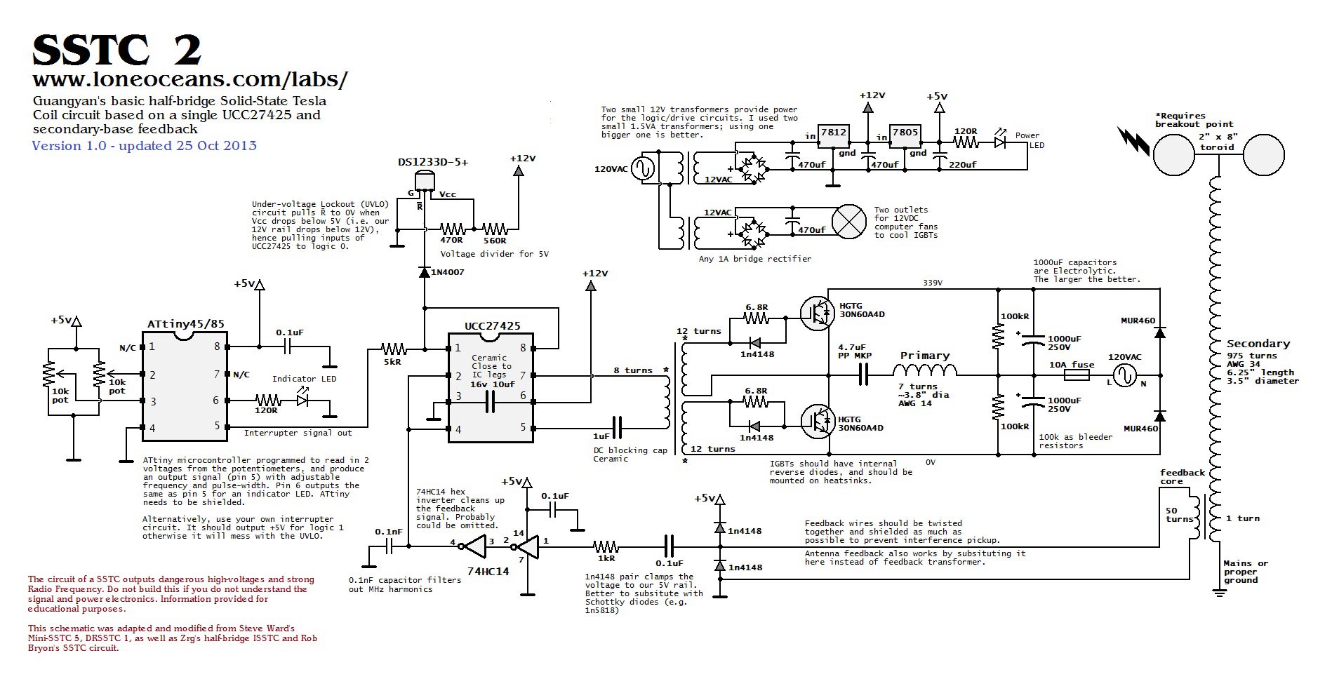