If you need assistance, please send an email to forum at 4hv dot org. To ensure your email is not marked as spam, please include the phrase "4hv help" in the subject line. You can also find assistance via IRC, at irc.shadowworld.net, room #hvcomm.
Support 4hv.org!
Donate:
4hv.org is hosted on a dedicated server. Unfortunately, this server costs and we rely on the help of site members to keep 4hv.org running. Please consider donating. We will place your name on the thanks list and you'll be helping to keep 4hv.org alive and free for everyone. Members whose names appear in red bold have donated recently. Green bold denotes those who have recently donated to keep the server carbon neutral.
Special Thanks To:
Aaron Holmes
Aaron Wheeler
Adam Horden
Alan Scrimgeour
Andre
Andrew Haynes
Anonymous000
asabase
Austin Weil
barney
Barry
Bert Hickman
Bill Kukowski
Blitzorn
Brandon Paradelas
Bruce Bowling
BubeeMike
Byong Park
Cesiumsponge
Chris F.
Chris Hooper
Corey Worthington
Derek Woodroffe
Dalus
Dan Strother
Daniel Davis
Daniel Uhrenholt
datasheetarchive
Dave Billington
Dave Marshall
David F.
Dennis Rogers
drelectrix
Dr. John Gudenas
Dr. Spark
E.TexasTesla
eastvoltresearch
Eirik Taylor
Erik Dyakov
Erlend^SE
Finn Hammer
Firebug24k
GalliumMan
Gary Peterson
George Slade
GhostNull
Gordon Mcknight
Graham Armitage
Grant
GreySoul
Henry H
IamSmooth
In memory of Leo Powning
Jacob Cash
James Howells
James Pawson
Jeff Greenfield
Jeff Thomas
Jesse Frost
Jim Mitchell
jlr134
Joe Mastroianni
John Forcina
John Oberg
John Willcutt
Jon Newcomb
klugesmith
Leslie Wright
Lutz Hoffman
Mads Barnkob
Martin King
Mats Karlsson
Matt Gibson
Matthew Guidry
mbd
Michael D'Angelo
Mikkel
mileswaldron
mister_rf
Neil Foster
Nick de Smith
Nick Soroka
nicklenorp
Nik
Norman Stanley
Patrick Coleman
Paul Brodie
Paul Jordan
Paul Montgomery
Ped
Peter Krogen
Peter Terren
PhilGood
Richard Feldman
Robert Bush
Royce Bailey
Scott Fusare
Scott Newman
smiffy
Stella
Steven Busic
Steve Conner
Steve Jones
Steve Ward
Sulaiman
Thomas Coyle
Thomas A. Wallace
Thomas W
Timo
Torch
Ulf Jonsson
vasil
Vaxian
vladi mazzilli
wastehl
Weston
William Kim
William N.
William Stehl
Wesley Venis
The aforementioned have contributed financially to the continuing triumph of 4hv.org. They are deserving of my most heartfelt thanks.
Registered Member #4237
Joined: Tue Nov 29 2011, 02:49PM
Location:
Posts: 117
Thank for your reply. I have a question regarding the switching:
The way my switching circuit is now, an IGBT receives a signal when a beam of light is broken. When the beam is restored, the IGBT turns off. I would like to expand the signal, so I can decide exactly how long it will take until the IGBT is turned off. Unfortunately, a circuit like this is a bit out of my ballpark. I've tried many different approaches, but none works. How should I go ahead and make this work? If you have a schematic for such a "signal expander" or whatever you could call it, I'd like to have a look!
Registered Member #1525
Joined: Mon Jun 09 2008, 12:16AM
Location: America
Posts: 294
Pinkamena wrote ...
Thank for your reply. I have a question regarding the switching:
The way my switching circuit is now, an IGBT receives a signal when a beam of light is broken. When the beam is restored, the IGBT turns off. I would like to expand the signal, so I can decide exactly how long it will take until the IGBT is turned off. Unfortunately, a circuit like this is a bit out of my ballpark. I've tried many different approaches, but none works. How should I go ahead and make this work? If you have a schematic for such a "signal expander" or whatever you could call it, I'd like to have a look!
Yes, the signal from the detector could trigger a simple NE555 in monostable mode which would then create a pulse with a duration of your choosing.
But the question is, why would you? Use another detector (or better, the same one) to turn it of when the projectile is in exactly the right position. That way you have closed loop control (exact time communicated), rather than open loop (pre-programmed guess).
Registered Member #4237
Joined: Tue Nov 29 2011, 02:49PM
Location:
Posts: 117
I would do that, but the problem is that the projectile will be inside the coil when I want to turn it off. Kind of hard to get a beam of light to pass through a coil XD Or are you perhaps thinking of another approach?
Registered Member #1451
Joined: Wed Apr 23 2008, 03:48AM
Location: Boulder, Co
Posts: 661
If the sensor is right at the start of the coil, and the projectile is the same length as the coil, then when it leaves the sensor and the IGBT turns off, it will be in exactly the center of the coil.
Registered Member #4237
Joined: Tue Nov 29 2011, 02:49PM
Location:
Posts: 117
Turkey9 wrote ...
If the sensor is right at the start of the coil, and the projectile is the same length as the coil, then when it leaves the sensor and the IGBT turns off, it will be in exactly the center of the coil.
Yes, but I thought the coils needed to be a little longer (About 1.5 the length of the projectile).
Registered Member #1525
Joined: Mon Jun 09 2008, 12:16AM
Location: America
Posts: 294
That depends on who you ask. I'd say always make your coil the same length, Barry says 1.33, others say 1.5. DARPA's massively multistaged coil mortar had coils that were maybe only 10% of the length of the projectile (although they maye have had more than one coil on at a time, im not sure). Nothing is absolute here, but anything between 1 and 1.5 should be good for a hobby coilgun.
Also, research actually suggests you place the detector a few mm before the entrance of the coil.
Registered Member #4237
Joined: Tue Nov 29 2011, 02:49PM
Location:
Posts: 117
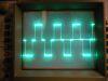
Hi guys, just thought I'd show you what I've been doing lately. I've made an interactive simulation in Wolfram Mathematica, showing the current as a function of time, coil thickness and air gap radius. In this simulation, time and air gap radius can be dynamically altered, to show how the current will flow in the coil. Resistance, inductance, and lenght (to always keep the projectile with a mass of 300 grams) is also calculated dynamically. The curve is "blocky" due to large increments of wire being added each time the coil thickness becomes large enough to add a new layer to the coil.
Here's an album with some screengrabs showing how current will flow in a coil using AWG18 (1.06 mm) with a resistance of 0.021 ohm/meter, and an inner coil diameter of 1.7 cm. (Notice the image that say "70ms". I forced the resistance down to 0.001 ohm to create some heavy ringing in the coil! Very fun.)
EDIT: I almost forgot, here's the code in case you have Mathematica and want to try it out yourself.
Registered Member #1451
Joined: Wed Apr 23 2008, 03:48AM
Location: Boulder, Co
Posts: 661
Nice. I don't know if mathematica can do this, but you should do a 3D plot with time on one of the axis. The peak current for each coil will be in different places as the turns vary so a 3D plot would be really interesting to see.
Registered Member #4237
Joined: Tue Nov 29 2011, 02:49PM
Location:
Posts: 117
That can be done, but it is VERY time consuming to plot it. I made a 3D plot with coil x=outer radius, y=coil inner radius, and z=current, and it took over 8 seconds to calculate it every time I changed the time variable. It is much easier to look at the 2D plot with a fixed inner coil radius.
EDIT: With an inner coil radius of 1 cm, and an outer coil radius of around 1.5 cm (still AWG18), I am getting a peak magnetic field strength of over 6000 kA/m (This is at 1 ms, @1800A. The magnetic field quickly drops 0, takes about 150ms). Does this seem very unlikely? I could also mention that at these coil specifications, the wire length is around 28 meters.
This site is powered by e107, which is released under the GNU GPL License. All work on this site, except where otherwise noted, is licensed under a Creative Commons Attribution-ShareAlike 2.5 License. By submitting any information to this site, you agree that anything submitted will be so licensed. Please read our Disclaimer and Policies page for information on your rights and responsibilities regarding this site.


 Some advices for my first coilgun