If you need assistance, please send an email to forum at 4hv dot org. To ensure your email is not marked as spam, please include the phrase "4hv help" in the subject line. You can also find assistance via IRC, at irc.shadowworld.net, room #hvcomm.
Support 4hv.org!
Donate:
4hv.org is hosted on a dedicated server. Unfortunately, this server costs and we rely on the help of site members to keep 4hv.org running. Please consider donating. We will place your name on the thanks list and you'll be helping to keep 4hv.org alive and free for everyone. Members whose names appear in red bold have donated recently. Green bold denotes those who have recently donated to keep the server carbon neutral.
Special Thanks To:
Aaron Holmes
Aaron Wheeler
Adam Horden
Alan Scrimgeour
Andre
Andrew Haynes
Anonymous000
asabase
Austin Weil
barney
Barry
Bert Hickman
Bill Kukowski
Blitzorn
Brandon Paradelas
Bruce Bowling
BubeeMike
Byong Park
Cesiumsponge
Chris F.
Chris Hooper
Corey Worthington
Derek Woodroffe
Dalus
Dan Strother
Daniel Davis
Daniel Uhrenholt
datasheetarchive
Dave Billington
Dave Marshall
David F.
Dennis Rogers
drelectrix
Dr. John Gudenas
Dr. Spark
E.TexasTesla
eastvoltresearch
Eirik Taylor
Erik Dyakov
Erlend^SE
Finn Hammer
Firebug24k
GalliumMan
Gary Peterson
George Slade
GhostNull
Gordon Mcknight
Graham Armitage
Grant
GreySoul
Henry H
IamSmooth
In memory of Leo Powning
Jacob Cash
James Howells
James Pawson
Jeff Greenfield
Jeff Thomas
Jesse Frost
Jim Mitchell
jlr134
Joe Mastroianni
John Forcina
John Oberg
John Willcutt
Jon Newcomb
klugesmith
Leslie Wright
Lutz Hoffman
Mads Barnkob
Martin King
Mats Karlsson
Matt Gibson
Matthew Guidry
mbd
Michael D'Angelo
Mikkel
mileswaldron
mister_rf
Neil Foster
Nick de Smith
Nick Soroka
nicklenorp
Nik
Norman Stanley
Patrick Coleman
Paul Brodie
Paul Jordan
Paul Montgomery
Ped
Peter Krogen
Peter Terren
PhilGood
Richard Feldman
Robert Bush
Royce Bailey
Scott Fusare
Scott Newman
smiffy
Stella
Steven Busic
Steve Conner
Steve Jones
Steve Ward
Sulaiman
Thomas Coyle
Thomas A. Wallace
Thomas W
Timo
Torch
Ulf Jonsson
vasil
Vaxian
vladi mazzilli
wastehl
Weston
William Kim
William N.
William Stehl
Wesley Venis
The aforementioned have contributed financially to the continuing triumph of 4hv.org. They are deserving of my most heartfelt thanks.
Registered Member #95
Joined: Thu Feb 09 2006, 04:57PM
Location: Norway
Posts: 1308
Every electronics forum has one of these, so I thought I'd contribute with mine. After repeated interest in my PLL induction heater and rev. 2 coming up, I couldn't bear the thought of using veroboard again. And what tops off an electronics project more than soldering it to a PCB you designed? So I researched different PCB production techniques, checked what my supplier had, and researched some more. Toner transfer seems to be the most commonly used method among hobbyists, but I don't have easy access to a laser printer, and definitely not one I can stuff magazine pages into without getting in trouble. With that ruled out, photoresist seemed the natural choice.
Except for the start-up costs.
550 EUR for a UV box? 340 for a PCB guillotine? Another 500 for an etching tank?
Fat chance. It's time for DIY. I had seen people use UV tubes, ballasts and the works to make something just like you can buy from a shop, but why? These days UV LEDs are cheap as dirt, and many times more efficient. A quick search on ebay revealed several lots of 100x UV LEDs from Asia (with FREE shipping!) for half the price of one UV tube. If that isn't awesome, the UV LEDs will last nearly indefinitely if used properly, and generate nearly no heat. While waiting for the LEDs to arrive I figured a timer would be nice so I could do consistent exposures. I still had a VFD from a gutted microwave oven, an old PIC16F84A and a bunch of switches soldered to a PCB from a monitor. What more could I ask for? Some programing later I had a functional timer, which would automatically control the UV LEDs, and remember the exposure time last used from it's EEPROM. I decided to use a A6810 shift register/VFD driver to free up some I/O pins. I'm glad I did, as the VFD is considerably brighter than the discrete driver I built for my Chronograph. I'll need to upgrade it later some time. I also used the original transformer to power the VFD, it's glued in the AT box which is why you can't see it. Firmware and schematic can be downloaded here: ]uv_led_developer_box.zip[/file]
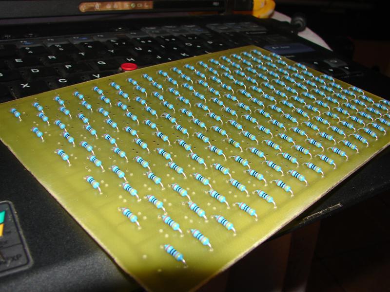
I decided to use 12V for the UV LEDs, as this would work fine with the old AT supply I decided to dedicate to this project. Each LED has a Vdrop of about 3.5V, which means I'll use 3 in series for 10.5V, so only 1.5V will be wasted in the current limiting resistor. Using an individual resistor for each LED is a waste of power, time and resources. I decided to fill a 16x 16cm matrix with LEDs, so rather large boards could be exposed. It would also make the most use of the 100 LEDs I had. The LEDs were mounted on standard veroboard.
What next? Wood-working of course! I purchased some new pine sheets for once, which look pretty good IMO. They smell nice too.
Now I bet you're wondering if my 30 EUR UV box can hold a match to the 550 EUR ones you can purchase from a supplier. To test it, I created a small PCB using (god-forbid) SMT. I wasn't happy with my previous travel charger, and with my new PCB setup I suddenly had access to the SMT chips as well, which almost all of the newer chips are sold as. My mom was so kind as to print out the PCB on a transparency, which would considerably lower the exposure time. As a replacement for the guillotine I simply scored the board on both sides with a Stanley knife, and snapped off the piece I needed. No fiberglass dust, and the cheap knife doesn't seemed dulled. No worries.
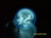
Set for 2min 30s, the suspence is killing me...
It looks to be etching alright... In case you're wondering, I developed it in NaOH for roughly 2 minutes. I had to take it out of the etcher a few times to redevelop, as I kept removing it prematurely in fear of all the photoresist being dissolved. The etcher I use is Sodium Persulfate. I kept it in a hot water bath, but it still took 30 minutes to fully etch the board. Maybe I'll need to make an etch tank next!
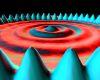
*Drum roll....* Tada!
It works perfectly! Notice even the tiny traces outlining the PCB turned out, and this was the first run without optimization! I can definitely recommend this method to anyone who wishes to make their own PCBs. It's cheap, clean, and fairly quick. And above all the PCBs turn out great!
Registered Member #618
Joined: Sat Mar 31 2007, 04:15AM
Location: Us-Great Lakes
Posts: 628
Astounding work as always Uzzors (been a while since I visited the forums and posted).
Uzzors, I didn't notice and specific measurements for distance from LED's to PCB to help others with a rough idea to produce good resolution, also I was wondering whats the smallest successful size trace and or spacing you have gotten out of this process using the UV LED exposure?
Just wondering some of this since I just bought some equipment to do this, was getting tired of PCB fab houses costs especially when Silkscreen and solder masking prices were included.
Registered Member #2261
Joined: Mon Aug 03 2009, 01:19AM
Location: London, UK
Posts: 581
Nicely done
Any idea what wavelength and power the LEDs are?
It's always been a bit of a mystery to me what wavelength of UV is needed for PCB exposure. I'd also worry whether the platen glass/plastic transmitted that UV or not. Everything I see suggests the requirements are very flexible so that anything close to but shorter than 400nM is ok, and being near 400nM, anything that's clear to the eye is probably clear that UV too.
Registered Member #95
Joined: Thu Feb 09 2006, 04:57PM
Location: Norway
Posts: 1308
Thanks guys. The distance from the UV LEDs was determined by eye. What I did was construct the LED matrix first, then take an A4 sheet of paper and move it away from the LEDs until I found the beam diffusion satisfisfactory. The exact distance will depend on your LED spacing and their emission angle. The LEDs I used have an angle of about 25 degrees, intensity is 320mcd and their wavelength is said to be 395-405nm. I purchased a batch liek this:
I haven't experimented with trace width yet, as I've only made one SMT board which you see above. If you use a transparency with the ink side towards the board, and space the LEDs far enough away you should be able to get tiny traces, provided your etching and developing techniques match up! The smaller traces in the above PCB are 0,015 inches, I'm sure 0,010 is entirely possible.
Registered Member #618
Joined: Sat Mar 31 2007, 04:15AM
Location: Us-Great Lakes
Posts: 628
THAT is absolutely fantastic Uzzors, especially since I just bought 100 of very similar 300nm leds, which I thought wouldn't be as good as the 3000+ mcd ones, but this is just amazing, if you ever get a chance before I get all my stuff set up mind attempting various trace thickness's and trace to trace spacing to see what kind of results you get?
If you're wondering why I'm concerned about trace sizes its because a micro-controller project I'm working on requires approx 4-7mil traces for the LQFP 48 package that the chip only comes in, I realize there are other chips especially ones that are in larger and even sdip packages but I like the architecture of this chip (Stmicro's STm8s105c6) even though the compiler I have for it will only allow me to use 50% of its memory 16K is still a lot of space and "power" especially for projects in our scale of work, as in I don't think any of us on this forum have an application where we actually need 32K+ memory for a project.
If I get my equipment and trace testing before you get around to if your up for it, I'll post some results at that time in case you or anyone else want to try various sized traces, also ever thought of making your exposure box set up for double sided as well?
Since you could just lay your bottom layer down 1st place the pcb on top of it then place the top layer on the pcb and a glass weight on top of that and with a some kind of edge alignment like a corner groove where you could place one corner of all your pcb traces and the board itself to help align them.
This site is powered by e107, which is released under the GNU GPL License. All work on this site, except where otherwise noted, is licensed under a Creative Commons Attribution-ShareAlike 2.5 License. By submitting any information to this site, you agree that anything submitted will be so licensed. Please read our Disclaimer and Policies page for information on your rights and responsibilities regarding this site.


 UV LED Exposure box for PCBs


