If you need assistance, please send an email to forum at 4hv dot org. To ensure your email is not marked as spam, please include the phrase "4hv help" in the subject line. You can also find assistance via IRC, at irc.shadowworld.net, room #hvcomm.
Support 4hv.org!
Donate:
4hv.org is hosted on a dedicated server. Unfortunately, this server costs and we rely on the help of site members to keep 4hv.org running. Please consider donating. We will place your name on the thanks list and you'll be helping to keep 4hv.org alive and free for everyone. Members whose names appear in red bold have donated recently. Green bold denotes those who have recently donated to keep the server carbon neutral.
Special Thanks To:
Aaron Holmes
Aaron Wheeler
Adam Horden
Alan Scrimgeour
Andre
Andrew Haynes
Anonymous000
asabase
Austin Weil
barney
Barry
Bert Hickman
Bill Kukowski
Blitzorn
Brandon Paradelas
Bruce Bowling
BubeeMike
Byong Park
Cesiumsponge
Chris F.
Chris Hooper
Corey Worthington
Derek Woodroffe
Dalus
Dan Strother
Daniel Davis
Daniel Uhrenholt
datasheetarchive
Dave Billington
Dave Marshall
David F.
Dennis Rogers
drelectrix
Dr. John Gudenas
Dr. Spark
E.TexasTesla
eastvoltresearch
Eirik Taylor
Erik Dyakov
Erlend^SE
Finn Hammer
Firebug24k
GalliumMan
Gary Peterson
George Slade
GhostNull
Gordon Mcknight
Graham Armitage
Grant
GreySoul
Henry H
IamSmooth
In memory of Leo Powning
Jacob Cash
James Howells
James Pawson
Jeff Greenfield
Jeff Thomas
Jesse Frost
Jim Mitchell
jlr134
Joe Mastroianni
John Forcina
John Oberg
John Willcutt
Jon Newcomb
klugesmith
Leslie Wright
Lutz Hoffman
Mads Barnkob
Martin King
Mats Karlsson
Matt Gibson
Matthew Guidry
mbd
Michael D'Angelo
Mikkel
mileswaldron
mister_rf
Neil Foster
Nick de Smith
Nick Soroka
nicklenorp
Nik
Norman Stanley
Patrick Coleman
Paul Brodie
Paul Jordan
Paul Montgomery
Ped
Peter Krogen
Peter Terren
PhilGood
Richard Feldman
Robert Bush
Royce Bailey
Scott Fusare
Scott Newman
smiffy
Stella
Steven Busic
Steve Conner
Steve Jones
Steve Ward
Sulaiman
Thomas Coyle
Thomas A. Wallace
Thomas W
Timo
Torch
Ulf Jonsson
vasil
Vaxian
vladi mazzilli
wastehl
Weston
William Kim
William N.
William Stehl
Wesley Venis
The aforementioned have contributed financially to the continuing triumph of 4hv.org. They are deserving of my most heartfelt thanks.
Registered Member #89
Joined: Thu Feb 09 2006, 02:40PM
Location: Zadar, Croatia
Posts: 3145
Finally a continuation of my DRSSTC project. (some changes here on 24. 6.)
Primary was far harder job than I tought, I couldnt get copper pipe right, it just get worse after each attempt of bending. I ended using thinner (2,7mm) wire finally to end that agony. For the beggining, some pics,, topic is (of course) going to be updated with progress.
New secondary: Fres with toroid ~120kHz (toroid is still too small) Primary cap: 125nF Primary inductance: about 15 uH Halfbridge of 30N60's. 320VDC full supply voltage. A mock-up of ATX box to shield electronics (proved to be pain to work with, and completly unnecessary).
pics of primary former construction:
I measured the resonant frequency, and it seems to be about 400kHz. Calculated frequency was a bit more than 300, so that worries me. I picked up almost exact 2,5us period on the scope, despite a bit blurry waveform on 1us divide:
update: april 15., 2006.
finished interrupter, ON time potentiometer is that small hole (as I need it to be somewhat public-proof). I dont want someone (or me) to flip the pot accidentaly and blow the coil up because of too high on-time.
Update, may 16. Finished and tested control board.
I got quite good waveform at output, nonpolar elecrolytic cap seems to quiet up ringing a bit but transistents aren't any faster than with normal caps.
Gate resistors of 3,9ohms slow the thing down a bit, I guess diodes will help there a bit (faster fall time) so let's say it's OK too.
Adding a 3,9 ohm resistor in paralell with cap (any) helps too, but I don't know how safe it is.
Last cycle seems to periodically dissapear, I can tune interrupter and RC timing circuit not to do it but it usually returns after a while.
I also saw this in other's waveforms so I think (i hope) it's normal. Cycle is always full so there will be no hard-switching.
One thing I added is interrupter failsafe circuit.
Firstly it is a resistive divider at interruptr input pin (to HC14) that divides the input voltage by about 3 (1K and 2,2K resistors)
If nothing is connectedit pulls the input of HC14 down so coil doesn't go on and explodes. Divider also saves HC14 from getting overvoltage on input (interrupter works at 15V so I get about 5V at input when high). It takes about 8-9 volts to actually pull it high, so there is no chance for accidental turnon.
Another thing is the pNP transistor that pulls interrupter output strongly down if enable signal goes eakly low. I use spare wire in the cable to carry back +15V to the base of transistor so it's off when interrupter is connected.
Actually resistor divider worked that good that there was no need of that, so it seems that it's only use will be just to turn on red led if interrupter is disconnected
Update may 17:
MMC, 125nF, 3.2kV (8x1uF 400V in series)
Caps are MKT, not the best but I hope they'l work for beggining. Resistors are behind, 6,8 megaohm on each cap.
Update 24.6.
Coil recently saw first light.
It's a bit mocked around the table but it's in running state.
I had problems with primary feedback, as it would oscillate only cycle or two and break down(??) causng poor output, no matter what on time I used. I checked everything on board again and it was fine. Rewound transformers are also fine.This left me no choice but to use antenna. ( ) I plugged the coil into mains, and got a 3cm streamer.
I saw something was wrong, and soon figured out that part of wire from top of the secondary fell deeply into it and arced over. It burned a hole in secondary, but it's just barely aestethic.
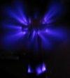
I repaired this and coil responded with nice 35cm streamer, on the pic down there. I got carried away and operated at sick ON-times,v probably I got over half amicrosecond (altough I promised myself to keep under 200us).
Sparks looked pretty nice, CW, and hot.
Then I turned the coil off, tried to tune the primary, and instantly - IGBT died I guess I made it too much away from ZCS, and it was already on the edge of dying.. Interestingly murphy law thing didn't work this time - another IGBT was alright, but ofcourse I replaced both. On 100V coil barely gave 8cm spark, not quite good.
Now I got a clue how to make primary feedback working - I seriesed a resistor directly with transformer output (I had to do this, no matter tha all conponents on that part probed fine).
Firstly it was 1k. It made the thing work during full ON period ( ) but current was leaping a bit. It increased almost by 50% of current before.
Now I increased he resistor to 10k and finally got a fine primary oscillation. The big question remains, how do other coils do that without my stupid resistor?
It seems like diodes are overloading CT or something, but everything is completely fine. In-built 1k resistor (after zeners) doesn't help here.
Now with primary feedback going I did low power tests again, at 100V I get 20cm sparks But that again requires high ON-time and high bang rate, probably about a kilohertz. I'm scared to give it full power yet. ZCS looks good to me, here are some pics and closeups.
20, 10 and 5 us div. Curent is just 20A because I was overloading power supply, it can give just a single shot at 100V so now i'm at some 20-30V.
Rectangular thing is gate signal of one IGBT. I had to slope it and trigger misses a bit at beggining. It's probably a trait of running both probes simultaneously.
Registered Member #89
Joined: Thu Feb 09 2006, 02:40PM
Location: Zadar, Croatia
Posts: 3145
Edit: I finished my interrupter, and beginning work on main control electronics. Also I un-messed up the thread a bit, so all the information goes into the first post.
Registered Member #15
Joined: Thu Feb 02 2006, 01:11PM
Location:
Posts: 3068
Desmogod wrote ...
Surely the interrupter would be better off in a shielded box?
Not necessarily. I never run my interruptors in shielded boxes, and considering most people run all their electronics underneath their DRSSTCs with no shielding and then go through the trouble with shielding the interruptor box is a bit silly. Or better yet, i've seen people run shielded interruptors and run non-shielded cables from the interruptor to the control electronics.
Registered Member #146
Joined: Sun Feb 12 2006, 04:21AM
Location: Austin Tx
Posts: 1055
My original interrupter was not shielded. It was fine *most* of the time, but if you brought it too close to the coil the frequency would increase a bit. The layout could affect this alot, and my layout was nothing to be desired .
The only suggestion i have is to put a bigger toroid on the coil. I usually make the toroid diameter equal to the secondary length. It just looks right in my opinion, and bigger toroids give better performance usually.
Registered Member #89
Joined: Thu Feb 09 2006, 02:40PM
Location: Zadar, Croatia
Posts: 3145
OK, board is done too.
Can I ask one small question: should I ground the GND of low voltage circuit, or i should just leave it and just put interrupter cable shield to the ground and leave everything else hang?
Registered Member #30
Joined: Fri Feb 03 2006, 10:52AM
Location: Glasgow, Scotland
Posts: 6706
All of my drivers have the "Odd jumping of last cycle" effect. It's a side effect of the sync circuit that only allows you to end the burst at zero crossings. I don't know if Steve Ward's design does it.
Registered Member #89
Joined: Thu Feb 09 2006, 02:40PM
Location: Zadar, Croatia
Posts: 3145
This is steve ward's, it's obivously caused by RC and bistable (sync circuit) reacting on irregularities on interrupter signal. I guess it's irrelevant then.
Registered Member #15
Joined: Thu Feb 02 2006, 01:11PM
Location:
Posts: 3068
In regards to Steve Ward's sync circuit, it (the circuit) does exhibit metastability problems or in otherwords, it can produce illegal states at the output of the flip-flop if you go through it and look at the waveforms. Not sure if this is a real issue in operation, but if you go through the calculations and simulations in PSPICE you can definitely see the illegal states.
Perhaps, this is what you could be seeing.
I have caught on a number of times the flip-flop latching up in this type of circuit (my synch circuit is very similar but has an extra flip-flop) during operation and staying high from time to time during the intrapulse period of operation.
This site is powered by e107, which is released under the GNU GPL License. All work on this site, except where otherwise noted, is licensed under a Creative Commons Attribution-ShareAlike 2.5 License. By submitting any information to this site, you agree that anything submitted will be so licensed. Please read our Disclaimer and Policies page for information on your rights and responsibilities regarding this site.


 My first DRSSTC


 )
)


 .
.