If you need assistance, please send an email to forum at 4hv dot org. To ensure your email is not marked as spam, please include the phrase "4hv help" in the subject line. You can also find assistance via IRC, at irc.shadowworld.net, room #hvcomm.
Support 4hv.org!
Donate:
4hv.org is hosted on a dedicated server. Unfortunately, this server costs and we rely on the help of site members to keep 4hv.org running. Please consider donating. We will place your name on the thanks list and you'll be helping to keep 4hv.org alive and free for everyone. Members whose names appear in red bold have donated recently. Green bold denotes those who have recently donated to keep the server carbon neutral.
Special Thanks To:
Aaron Holmes
Aaron Wheeler
Adam Horden
Alan Scrimgeour
Andre
Andrew Haynes
Anonymous000
asabase
Austin Weil
barney
Barry
Bert Hickman
Bill Kukowski
Blitzorn
Brandon Paradelas
Bruce Bowling
BubeeMike
Byong Park
Cesiumsponge
Chris F.
Chris Hooper
Corey Worthington
Derek Woodroffe
Dalus
Dan Strother
Daniel Davis
Daniel Uhrenholt
datasheetarchive
Dave Billington
Dave Marshall
David F.
Dennis Rogers
drelectrix
Dr. John Gudenas
Dr. Spark
E.TexasTesla
eastvoltresearch
Eirik Taylor
Erik Dyakov
Erlend^SE
Finn Hammer
Firebug24k
GalliumMan
Gary Peterson
George Slade
GhostNull
Gordon Mcknight
Graham Armitage
Grant
GreySoul
Henry H
IamSmooth
In memory of Leo Powning
Jacob Cash
James Howells
James Pawson
Jeff Greenfield
Jeff Thomas
Jesse Frost
Jim Mitchell
jlr134
Joe Mastroianni
John Forcina
John Oberg
John Willcutt
Jon Newcomb
klugesmith
Leslie Wright
Lutz Hoffman
Mads Barnkob
Martin King
Mats Karlsson
Matt Gibson
Matthew Guidry
mbd
Michael D'Angelo
Mikkel
mileswaldron
mister_rf
Neil Foster
Nick de Smith
Nick Soroka
nicklenorp
Nik
Norman Stanley
Patrick Coleman
Paul Brodie
Paul Jordan
Paul Montgomery
Ped
Peter Krogen
Peter Terren
PhilGood
Richard Feldman
Robert Bush
Royce Bailey
Scott Fusare
Scott Newman
smiffy
Stella
Steven Busic
Steve Conner
Steve Jones
Steve Ward
Sulaiman
Thomas Coyle
Thomas A. Wallace
Thomas W
Timo
Torch
Ulf Jonsson
vasil
Vaxian
vladi mazzilli
wastehl
Weston
William Kim
William N.
William Stehl
Wesley Venis
The aforementioned have contributed financially to the continuing triumph of 4hv.org. They are deserving of my most heartfelt thanks.
Registered Member #618
Joined: Sat Mar 31 2007, 04:15AM
Location: Us-Great Lakes
Posts: 628
Well the wire came in today while I was at work, for the SSTC that I'm working on. Which is built on Steve wards Mini-SSTC, with almost identical specs...coincidentally. Still waiting on parts to arrive for driver and power electronics.
So far here is the progress, I managed to get all 18" on the coil wound with 30awg wire in about 3.5 hours.
The pictures of the finished coil on the winding rig, and on a table finished and drying. The rig is two lawn chairs supporting a threaded rod that ran between the two chairs and in the middle of the coil.
I sorta fixed the linking, For some reason the image resizing thing isn't working for me anymore.
Update: Sat 10AM: Well All my parts came in on Thursday and I started working on it so far everythings working fine minus the little GDT issue but I believe thats been fixed. Tried to build the remote interuptor, but it failed so I'm gonna try and fix that today after I get a new perfboard from Radioshack along with some thermal compound since I'm out, I'll add some pics of the progress after I get everything soldered and boldy go into the 120VAC powering stage.
Things to do still: Make remote interuptor work in control box Solder drive and power electronics to perfboard Hook up coil to electronics and test Make topload Make housing\stand for entire system Post pics on forums of progress
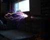
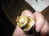
Update time 11:30PM saturday! Well got everything soldered and on the perf boards was testing UCC outputs when the 1st casualty hit ,luckily I had a replacement one, after I got that I figured it was time to take a pic of the boards progress before I got the power caps, power lines, and recovery diodes in , Well Managed to get the whole setup semi wired and tested and here what the setup looked like ,Fired her up and was getting kinda crapy arcs almost as if I was just running a micro coil with 5v's input, it was enough to put a blue plasma ball ontop of the wires tip, and arc to a florescent and light it up, but other then that it was crap, Except for whe never I'd switch to a different interuptor value it would do a massive 4in discharge (So no pics of it running ). Anyways I switched the primary coil around and stopped teh interuptor halfway between two settings and I was able to produce some really nice arcs for about 10seconds then the dining rooms circuit breaker popped (20A) , left the power electronics plugged in and flipped the breaker then Boom the (-) rail fet's gate drive resistor flashed over I think... , . Just noticed I forgot to insert the pics of some of the setup, , ,
Registered Member #618
Joined: Sat Mar 31 2007, 04:15AM
Location: Us-Great Lakes
Posts: 628
As for power....I guess what ever the bridge rectifier will limit it to...which is 10A, so I guess 1.2kW. I never really thought of how much power I was going to put into it...
Registered Member #105
Joined: Thu Feb 09 2006, 08:54PM
Location:
Posts: 408
I'd get a bigger bridge rectifier- with a secondary that size, the rectifier will most likely be the limiting factor- I had a 10A rectifier, and was running 16 inch sparks on a 4" by 12" secondary- however, CW i was drawing nearly 2kw, and the rectifier blew after some time. What MOSFETS or IGBTs will you be using?
Registered Member #618
Joined: Sat Mar 31 2007, 04:15AM
Location: Us-Great Lakes
Posts: 628
Irfp260n's I'm gonna follow the schematic to the letter almost, unless a part is either obsolete or not specified. If thats the case though Edy, what you you or anyone for that matter suggest, with the exception of a variac? Also would one say make a helical primary out of Cu tubing and have it about 1\2"away, or just find something to cover the lower part of the secondary and just wrap large AWG wire around it? Now this questions got me wondering, since having sharp points, i.e if I bend the output wire a say a 90 degree turn to connect to the toploads bolt, it would act as a discharge point, but what if I make a Plexiglas disc, and make a trace out of Al tape from the bolt to where the wire makes the bend, would it still act as a discharge point or would it help convey all the energy to the topload bolt?
Registered Member #593
Joined: Tue Mar 20 2007, 12:32AM
Location:
Posts: 50
Whitearc,
I would use some poly sheeting of some type to wrap around the base of the secondary for insulation and wind a 4-5 turn primary directly over it, near the bottom of the secondary. Just a few minutes ago I was running my very similar system with a smaller 3" secondary (my 4.5 x 12.5 is in use in another TC project right now). I used a primary that was wrapped around a 4 inch pvc section for 4 turns. This setup gives a definate decrease in spark when compared to running the same 3" secondary with higher coupling. Several inches difference in fact. If you really want longer sparks I would go for the higher coupling. It's pretty important in this type of system. After I built Steve's Micro and Mini SSTC projects, I did a lot of comparitive tests playing around with varying degrees of coupling. I also used both drivers to ring all the secondaries I have around the lab and take notes on their Fres while wearing various toroids, and unloaded. This allowed me to have a good perspective about the effects of different primaries. Generally higher coupling resulted in hotter and longer sparks, but if too high resulted in more heating of the mosfet. Especially in CW mode this becomes significant fast. However, with secondaries in the 100Khz vicinity, my IRFP260N's ran cold in CW mode, until I started drawing constant power arcs. Even then it was amazing what they could hold up to. I still haven't blown the ones in my half bridge.
Some people have used sections of a 2-3 liter bottle, cut out and electric taped onto the secondary windings, I used some cuttings of plastic from the large 1 gallon zip lock bags. One thing you might do, if you have any, is use neon sign high voltage wire...however I've only seen that up to about 16 gauge, and I prefer using 12-10 AWG for my SSTC primaries.
Registered Member #538
Joined: Sun Feb 18 2007, 08:33PM
Location: Finland
Posts: 181
Brett Miller wrote ...
Whitearc,
I would use some poly sheeting of some type to wrap around the base of the secondary for insulation and wind a 4-5 turn primary directly over it, near the bottom of the secondary.
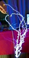
I wouldnt suggest doing this based on my own imperical tests :P Heres my SSTC running where you can see the primary: The secondary has a few layers of polypropylene wrapped around it and the primary wound directly over it, it DID produce longer sparks than with a lower coupling but then a bit after that pic it arced over killing the FETs.
Registered Member #618
Joined: Sat Mar 31 2007, 04:15AM
Location: Us-Great Lakes
Posts: 628
Yea I figured even if I used the 2 liter bottle idea, using several bottles and layering the plastic, that the voltage on the secondary would still be arc through or over. The one thing I can't remember though, is do you connect the ground of the secondary to the ground terminal of the RFI filter (I think not, but still asking), or do you just run a decent sized to a pole in ground?
Registered Member #105
Joined: Thu Feb 09 2006, 08:54PM
Location:
Posts: 408
For one, if you are running only 1.2kw which is limited by your rectifier, there is little reason to use copper tubing in the primary- I used 10 or 12 gauge wire in my primary- much cheaper, and didn't get warm when running ~2000W. I would really recommend using a bigger rectifier though, its not a big cost item, and It will allow your coil to run at much higher powers which that size secondary is begging for Try :
Registered Member #618
Joined: Sat Mar 31 2007, 04:15AM
Location: Us-Great Lakes
Posts: 628
Well I got the electronics in today, and it turns out...I forgot to read my order on the value of the bridge, which is actually 15A 400v. Its funny that you say use 10awg, because I was thinking of doing some low V tests and managed to dig up some old 10awg, that I previously used as a power wire for a car audio system, before I bought the huge 3 awg and 100amp fuse for the car, lol. Now the only tasks I have left to do, get a primary insulator(a tube to isolate the primary and secondary, as well as providing a place to wrap the primary around) Prototype the electronics on a bread board, get a perf board, enclosure for the remote interrupter, low voltage test then wire up the whole thing and assemble it on a wood or plexi glass stand put a mesh cage around the electronics! All before Monday when I start my new job YAY!~
This site is powered by e107, which is released under the GNU GPL License. All work on this site, except where otherwise noted, is licensed under a Creative Commons Attribution-ShareAlike 2.5 License. By submitting any information to this site, you agree that anything submitted will be so licensed. Please read our Disclaimer and Policies page for information on your rights and responsibilities regarding this site.


 The semi portable mammoth SSTC


 ). Anyways I switched the primary coil around and stopped teh interuptor halfway between two settings and I was able to produce some really nice arcs for about 10seconds then the dining rooms circuit breaker popped (20A)
  , left the power electronics plugged in and flipped the breaker then Boom the (-) rail fet's gate drive resistor flashed over I think...


 Try :
Try :