If you need assistance, please send an email to forum at 4hv dot org. To ensure your email is not marked as spam, please include the phrase "4hv help" in the subject line. You can also find assistance via IRC, at irc.shadowworld.net, room #hvcomm.
Support 4hv.org!
Donate:
4hv.org is hosted on a dedicated server. Unfortunately, this server costs and we rely on the help of site members to keep 4hv.org running. Please consider donating. We will place your name on the thanks list and you'll be helping to keep 4hv.org alive and free for everyone. Members whose names appear in red bold have donated recently. Green bold denotes those who have recently donated to keep the server carbon neutral.
Special Thanks To:
Aaron Holmes
Aaron Wheeler
Adam Horden
Alan Scrimgeour
Andre
Andrew Haynes
Anonymous000
asabase
Austin Weil
barney
Barry
Bert Hickman
Bill Kukowski
Blitzorn
Brandon Paradelas
Bruce Bowling
BubeeMike
Byong Park
Cesiumsponge
Chris F.
Chris Hooper
Corey Worthington
Derek Woodroffe
Dalus
Dan Strother
Daniel Davis
Daniel Uhrenholt
datasheetarchive
Dave Billington
Dave Marshall
David F.
Dennis Rogers
drelectrix
Dr. John Gudenas
Dr. Spark
E.TexasTesla
eastvoltresearch
Eirik Taylor
Erik Dyakov
Erlend^SE
Finn Hammer
Firebug24k
GalliumMan
Gary Peterson
George Slade
GhostNull
Gordon Mcknight
Graham Armitage
Grant
GreySoul
Henry H
IamSmooth
In memory of Leo Powning
Jacob Cash
James Howells
James Pawson
Jeff Greenfield
Jeff Thomas
Jesse Frost
Jim Mitchell
jlr134
Joe Mastroianni
John Forcina
John Oberg
John Willcutt
Jon Newcomb
klugesmith
Leslie Wright
Lutz Hoffman
Mads Barnkob
Martin King
Mats Karlsson
Matt Gibson
Matthew Guidry
mbd
Michael D'Angelo
Mikkel
mileswaldron
mister_rf
Neil Foster
Nick de Smith
Nick Soroka
nicklenorp
Nik
Norman Stanley
Patrick Coleman
Paul Brodie
Paul Jordan
Paul Montgomery
Ped
Peter Krogen
Peter Terren
PhilGood
Richard Feldman
Robert Bush
Royce Bailey
Scott Fusare
Scott Newman
smiffy
Stella
Steven Busic
Steve Conner
Steve Jones
Steve Ward
Sulaiman
Thomas Coyle
Thomas A. Wallace
Thomas W
Timo
Torch
Ulf Jonsson
vasil
Vaxian
vladi mazzilli
wastehl
Weston
William Kim
William N.
William Stehl
Wesley Venis
The aforementioned have contributed financially to the continuing triumph of 4hv.org. They are deserving of my most heartfelt thanks.
Registered Member #3395
Joined: Thu Nov 04 2010, 08:42AM
Location: Christchurch, New Zealand
Posts: 193
Hi all,
I have made several posts about troubleshooting my ZVS Flyback driver which I have made several threads about in the last few years or so and I'm aware the ZVS is very popular albeit can be unreliable. I think this is because the simple design of the circuit only controls a few variables which influence the circuit's performance, and a lot of other variables are left uncontrolled which can cause confusion for people trying to troubleshoot it.
However, I have had more reliable success having rebuilt it for the 3rd time. Note by success I mean running the circuit multiple times for longer durations without failure. I consulted my electronics mentor, who is a power engineer working on the transmission lines in New Zealand, and he gave me perhaps the tip that changed everything. As I have been consistently using SLAs to power my ZVS, I had also been having multiple failures immediately upon switch-on. I am now using an inline resistor when switching on initially to limit any inrush current, which is then shorted out to allow full operating current to flow. So far I have had no failures at switch on using IRFP250 MOSFETs.
I also placed the resonant capacitor closer to the flyback's primary as per one suggestion I saw on Youtube, took care not to run the IRFP250s over a supply voltage of 36V (48v is more likely over 50V when SLAs fully charged, 4 x 50V = 200V, which exceeds IRFP250's 200V limit, as the circuit diagram mentions)
In order to be able to run it safely on 48V, I replaced the 250s with HGTG30N60B3D IGBTs (600V 60A, very fast) as I needed a higher voltage rating as well as being fast (also tried GT60N321 - 1000V 60A -, far too slow and heated up considerably at 12V) So far works reliably at 48V, IGBTs are mounted on a large heatsink with good quality thermal grease and are force air cooled. They don't get warm after 2 minutes arcing operation, but needs to be run for a duration of 10-15 minutes to test the reliability.
I intend to separate the gate drive and flyback power supply to increase the flyback voltage without having to modify the gate driving circuit. Now that my circuit is so far proving to be reliable enough, I want to increase the HV side current output. I have thought about running 3 flybacks in parallel (both primaries and secondaries in parallel).
Can I please have some advice about the following points:
- phasing of the primary windings i.e: do the 3 separate primary windings have to turn in the same direction or do some have to be wound in the opposite direction?
- if the primaries are wound in parallel, then the effective inductance will be roughly 1/3, so the capacitance needs to be tripled in order to maintain the resonating frequency? I may parallel some IGBTs to increase the current capability
- although the ZVS self-resonates depending on the inductance and capacitance of the tank circuit, will a flyback perform better and have a higher power output (voltage and/or current) if the capacitance is changed so that the ZVS resonates at the frequency the flyback was designed to run at?
Many regards and thanks in advance, Cheers
EDIT: I have only learnt about series resonance at high school at the moment, but I'm aware parallel resonances operates differently.
Registered Member #11591
Joined: Wed Mar 20 2013, 08:20PM
Location: UK
Posts: 556
With regard to your first two points: If the secondaries are connected "nose to tail" then the primaries will have to be to maintain the right phasing. Doing this, however, will mean that the insulation between the primary and secondary of the flyback will have to withstand the total voltage of the stack (30kV+). This will probably be a problem.
Yes, to keep the frequency the same, the capacitance will have to be changed to make up for the drop in inductance, however this will affect more than just frequency: the quality factor of the coil will change dramatically, and with the finicky ZVS driver, anything could happen... It may change reliability, efficiency, output power, whether it actually oscillates or not, etc... Driving flybacks, changing values like that don't tend to cause catastrophic failures as often as with induction heaters or wireless power transmission (which can both be used with a standard ZVS driver (I tried and killed too many MOSFETs)) but Royer / Mazilli ZVS still tend to be a little unpredictable as well as unreliable (in my experience).
Registered Member #3395
Joined: Thu Nov 04 2010, 08:42AM
Location: Christchurch, New Zealand
Posts: 193
hen918 wrote ...
With regard to your first two points: If the secondaries are connected "nose to tail" then the primaries will have to be to maintain the right phasing. Doing this, however, will mean that the insulation between the primary and secondary of the flyback will have to withstand the total voltage of the stack (30kV+). This will probably be a problem.
I'm not quite sure what you mean by "nose to tail", but I intend to parallel the high voltage outputs and not connect them in series. Nose to tail sounds like connecting the flyback's HV output lead to the ground/cold side of another flyback?
I think you might have missed a word when mentioning the phasing, you didn't specify what direction
Registered Member #3395
Joined: Thu Nov 04 2010, 08:42AM
Location: Christchurch, New Zealand
Posts: 193
dexter, that's a good point though. It's just I had 3 similar flybacks and I'd like to get them all going in one setup. So this will mean I wind a 5 + 5 primary on each flyback, and make sure they are in parallel and are wound in the same direction?
Registered Member #42796
Joined: Mon Jan 13 2014, 06:34PM
Location:
Posts: 195
Kiwihvguy wrote ...
dexter, that's a good point though. It's just I had 3 similar flybacks and I'd like to get them all going in one setup. So this will mean I wind a 5 + 5 primary on each flyback, and make sure they are in parallel and are wound in the same direction?
no for 2 flybacks you just put the cores together and wind one single 5+5 primary on both like this:
Registered Member #11591
Joined: Wed Mar 20 2013, 08:20PM
Location: UK
Posts: 556
Kiwihvguy wrote ...
hen918 wrote ...
With regard to your first two points: If the secondaries are connected "nose to tail" then the primaries will have to be to maintain the right phasing. Doing this, however, will mean that the insulation between the primary and secondary of the flyback will have to withstand the total voltage of the stack (30kV+). This will probably be a problem.
I'm not quite sure what you mean by "nose to tail", but I intend to parallel the high voltage outputs and not connect them in series. Nose to tail sounds like connecting the flyback's HV output lead to the ground/cold side of another flyback? ...
I meant series as you thought, as this isn't a problem. As for the phasing, yes, the primary has to be wound so that all of the flybacks are the same. It might be easier to wire the primaries in series. which shouldn't present a problem with the ZVS driver.
Registered Member #3395
Joined: Thu Nov 04 2010, 08:42AM
Location: Christchurch, New Zealand
Posts: 193
Hey guys,
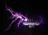
Have managed to construct and get the triple flyback stack running so far. I had to make a few modifications such as paralleling 2 IGBTs in place of one, increasing the size of the resonant capacitor to handle the greater resonant currents etc.
It draws 26 amps at 36v from the SLAs, the arc is noticeably fatter and hotter than my single flyback setup before.
One concern I have before I am confident to test it at higher voltages for longer durations, I am worried that if I start drawing a lot of current, the inductors may saturate and cease to act as inductors, which wouldn't be too good. I have a feeling I might need to put some more in series and parallel to increase the current capability.
Does anyone have any advice or formulae I can use to ensure my inductors are big enough?
This site is powered by e107, which is released under the GNU GPL License. All work on this site, except where otherwise noted, is licensed under a Creative Commons Attribution-ShareAlike 2.5 License. By submitting any information to this site, you agree that anything submitted will be so licensed. Please read our Disclaimer and Policies page for information on your rights and responsibilities regarding this site.


 Triple Flyback Stack advice wanted