If you need assistance, please send an email to forum at 4hv dot org. To ensure your email is not marked as spam, please include the phrase "4hv help" in the subject line. You can also find assistance via IRC, at irc.shadowworld.net, room #hvcomm.
Support 4hv.org!
Donate:
4hv.org is hosted on a dedicated server. Unfortunately, this server costs and we rely on the help of site members to keep 4hv.org running. Please consider donating. We will place your name on the thanks list and you'll be helping to keep 4hv.org alive and free for everyone. Members whose names appear in red bold have donated recently. Green bold denotes those who have recently donated to keep the server carbon neutral.
Special Thanks To:
Aaron Holmes
Aaron Wheeler
Adam Horden
Alan Scrimgeour
Andre
Andrew Haynes
Anonymous000
asabase
Austin Weil
barney
Barry
Bert Hickman
Bill Kukowski
Blitzorn
Brandon Paradelas
Bruce Bowling
BubeeMike
Byong Park
Cesiumsponge
Chris F.
Chris Hooper
Corey Worthington
Derek Woodroffe
Dalus
Dan Strother
Daniel Davis
Daniel Uhrenholt
datasheetarchive
Dave Billington
Dave Marshall
David F.
Dennis Rogers
drelectrix
Dr. John Gudenas
Dr. Spark
E.TexasTesla
eastvoltresearch
Eirik Taylor
Erik Dyakov
Erlend^SE
Finn Hammer
Firebug24k
GalliumMan
Gary Peterson
George Slade
GhostNull
Gordon Mcknight
Graham Armitage
Grant
GreySoul
Henry H
IamSmooth
In memory of Leo Powning
Jacob Cash
James Howells
James Pawson
Jeff Greenfield
Jeff Thomas
Jesse Frost
Jim Mitchell
jlr134
Joe Mastroianni
John Forcina
John Oberg
John Willcutt
Jon Newcomb
klugesmith
Leslie Wright
Lutz Hoffman
Mads Barnkob
Martin King
Mats Karlsson
Matt Gibson
Matthew Guidry
mbd
Michael D'Angelo
Mikkel
mileswaldron
mister_rf
Neil Foster
Nick de Smith
Nick Soroka
nicklenorp
Nik
Norman Stanley
Patrick Coleman
Paul Brodie
Paul Jordan
Paul Montgomery
Ped
Peter Krogen
Peter Terren
PhilGood
Richard Feldman
Robert Bush
Royce Bailey
Scott Fusare
Scott Newman
smiffy
Stella
Steven Busic
Steve Conner
Steve Jones
Steve Ward
Sulaiman
Thomas Coyle
Thomas A. Wallace
Thomas W
Timo
Torch
Ulf Jonsson
vasil
Vaxian
vladi mazzilli
wastehl
Weston
William Kim
William N.
William Stehl
Wesley Venis
The aforementioned have contributed financially to the continuing triumph of 4hv.org. They are deserving of my most heartfelt thanks.
Registered Member #192
Joined: Fri Feb 17 2006, 03:08AM
Location: Canada
Posts: 44
Well I now have this circuit just SMOKIN'
I tried different caps for the resonant cap and eventually put a 2 uf metal film poly cap (this made a hugh difference). I also added caps across the input to the supply, I used a 0.68uf metal film poly cap and a BIG electroylic cap (this improved the output too).
To prevent the flyback from flashing over I jumpered a couple of the secondary windings to joint them together since one set of inner coils were floating. This is a BIG old flyback!
I can now run 36 volts into the royer circuit and the output is amazingly powerfull. It make a real nice jaccobs ladder. I can't measure the current, I tried with two DC current clamps and they give erronius readings on a DVM (I used the Min - Max feature). I also tried with another DVM that can measure 20 amps for a short bit - garbage!. It seams to be drawing more than 20 amps though.
The 14 gauge wires to the flyback primary get warm. The heat sinks get hot and so do the L1 air wound coil. I used 18 gauge for L1
Any suggestions on how I can measure the current realibly?
Registered Member #162
Joined: Mon Feb 13 2006, 10:25AM
Location: United Kingdom
Posts: 3140
The simplest way to measure the dc current is with a moving coil meter which displays AVERAGE current. Whenever I use my dmm near arcs/sparks it gives erratic readings. I suspect rf pickup. (connect both dmm leads to 0v and check the reading)
When no arcs/sparks are present a 'Royer' should have a clean sinewave oscillation F=1/2.pi.sqrt(Cp.Lp)
Flyback transformers have a naturally resonant secondary, somewhere around 50 kHz operating at this frequency gives best performance.
At 35 volts dc input you should get about 75 Vrms across the primary inductance/capacitance with 0.68uF at 27 kHz the capacitor current would be about 8.7 Arms, ok for a good capacitor. 0.68 uF at 27 kHz implies a primary inductance of 51 uH I like to use at least 10x Lp for the dc inductor, so to me 128 uH is a little low.
I also use 30N60 with great success. I do prefer driving the igbt gate resistors from a separate supply of 12 to 15 Vdc (no zener diodes required) IF you do this it's best to connect the gate drive voltage first, then the power via the dc inductor. You will notice that with just the gate drive the 'Royer' oscillates due to parasitics.
Registered Member #192
Joined: Fri Feb 17 2006, 03:08AM
Location: Canada
Posts: 44
Well with some work I was able to measure the DC current to the Royer circuit, I'm drawing 13 amps at maximum arc length with 36 volts applied to it. I first tried to use an old simpson VOM that I bought at a ham radio flea market. The thing was way out of calibration, but after recalibrating it, I pin the needle once I draw out an arc on the 10 amps range. Then I remembered seeing a old phillips current shunt in a cupboard at work, so I checked it and it works fine. I'm still using a DMM but I have it located a good distance from the circuit and I check it for noise pickup - no problem.
I now need a bigger inductor, larger diameter wire and more number of turns. 18 gauge magnet wire heats up pretty quick at these currents. Also I need bigger heatsinks as they heat up almost as much as the L1 inductor. Or maybe a fan would do the trick?
---edit--- I found another trick to get more power out of this circuit. I put a heavy duty capacitor across where L1 connects to the flyback primary center tap and ground (battery neg). The arcs seem hotter. I just used a 0.68uf pulse cap.
Does anyone have suggestions to make the royer better?
Registered Member #152
Joined: Sun Feb 12 2006, 03:36PM
Location: Czech Rep.
Posts: 3384
Colin 99 wrote ...
I found another trick to get more power out of this circuit. I put a heavy duty capacitor across where L1 connects to the flyback center winding and neg. The arcs seem hotter. I just used a 0.68uf pulse cap.
I think that doing this bypasses the inductor, so I don't think it's a good idea
Registered Member #162
Joined: Mon Feb 13 2006, 10:25AM
Location: United Kingdom
Posts: 3140
Depends what result you want;
For a good sinewave at constant output voltage the primary 'Q' must be AT LEAST 2.4 ('Q' here is VAR in the resonant capacitor divided by output power) and a fairly large series (constant current) inductor. This will ensure zero-voltage-switching.
For maximum power output squarewave 'hard-switching' will give the best performance. (NO SERIES INDUCTOR OR RESONANT CAPACITOR)
Using a series inductor with some capacitance from the primary midpoint to 0v gives more power output than a true cfpr ('Royer') at the cost of higher switching losses, the series inductor will then provide soft startup and allow for some capacitive output load.
Overall, for a given quantity of ferrite and wire I like; cfpr ('Royer') invertor for constant voltage sinewave output Flyback for constant power/capacitor charging/eht output hard-switched push-pull for maximum power at constant output voltage.
Registered Member #192
Joined: Fri Feb 17 2006, 03:08AM
Location: Canada
Posts: 44
Quote: Using a series inductor with some capacitance from the primary midpoint to 0v gives more power output than a true cfpr ('Royer') at the cost of higher switching losses, the series inductor will then provide soft startup and allow for some capacitive output load.
That would explain why my heat sinks were getting so much hotter after I added that cap across it.
Now that I know, I think I'll remove it. - thanks
Could you further explain the Q factor? I guess I need to know how to measure it. For the record I'm using the flyback the way it came, I didn't change the gap. I'm using 14 gauge wire for the 10 turn primary and I'm using a pulse rated (metal foil) resonant capacitor.
It looks like if I increase the series inductance, I'll get closer to zvs and less heat on the heat sinks.
Registered Member #162
Joined: Mon Feb 13 2006, 10:25AM
Location: United Kingdom
Posts: 3140
First, as Firkragg mentioned above; I doubt that your flyback transformer can handle the power that you're trying to push through it. I suggest you change to true flyback operation. A 555 directly driving a 30N60 would work very well (A combination that I use) This would give a MUCH higher output voltage to operate your Jacobs Ladder and run for much longer on your batteries. One 12V battery should be good for powering the 555 and the flyback.
To answer your question, the 'Q' of your 'Royer' is not possible to calculate because you are not running at constant power output with a Jacobs Ladder, and I'm pretty sure you're saturating the core anyway. IF you were operating in zvs mode; The primary VAR with 35 Vdc supply would be 75 Vrms x 8.7 Arms = 652.5 VAR (for 0.68 uF at 27 kHz) so the MAXIMUM output power should be 652.5 / 2.4 = 272 Watts (sorry, I can't remember the reference for 'Q' >= 2.4 for zvs)
EDIT: If you do convert to true flyback operation the resulting eht power supply would be good for - Jacobs Ladder (with or without a diode) - Small sparkgap Tesla Coil (with a diode) - Plasma Globe (without a diode) - Capacitor charging (Pulse discharge etc.) (with a diode) - Lifter (with diode) etc. etc. A 'Royer' is ONLY really suitable for constant voltage output)
Registered Member #89
Joined: Thu Feb 09 2006, 02:40PM
Location: Zadar, Croatia
Posts: 3145
Flyback operation actually wouldn't do that much difference, since current is also what helps the arc to remain hot and stretch many times it's strike distance with jacob's ladder.
Many people use this circuit and get some scary JL outputs with it.
It's simply the amount of power you get into the flyback (more power = bigger spark), and flyback has it's limits. If voltage gets too high, it breaks down. If it is overcurrented, it dies again.
Mazzili circuit is generally a great way to do drive anything that doesn't require regulation or high input voltages, and is incredibly simple.
If you are saturating the core you'l need to use a smaller tank cap.
colin: what sparks do you get at full power input?
Some losses are simply unavoidable, and when you consider pushing 20amps through IRFP460's (270miliohms) you automatically get 5,8 volts of drop (DC!) and 108 watts of dissipation
IGBT's are also going to drop a few volts, and may be somewhat more efficient at that currens; but you will still be burning lots of power on them no matter what you do.
Flyback converter may require even higher voltage device and would burn a heck more power on switching losses.
If I had to operate this curcuit at such monstrous powers, I would seriously consider to do it directly from mains (110V is ideal to use with 600V IGBT's).
You could get much more power while keping IGBT's happy.
YOur flyback, whatever it is, must be a veteran now
Registered Member #192
Joined: Fri Feb 17 2006, 03:08AM
Location: Canada
Posts: 44
Thank you all for your replies. This type of circuit is new to me and so are igbts.
I scoped the royer circuit at the resonant capacitor (to battery neg) that I'm using which is 2uF. With 36 volts input: I get 84 volts peak at each end and it's a nice clean, smooth half sine wave. When I pull a long arc the wave shape changes to a slightly distorted, lower amplitude half triangle wave (in between a sine wave and triangle wave). I also tried at 24v input and I get the same shapes. If I was saturating I would expect flatenning or a high peak at the top of the sine wave which I'm not getting.
My big flyback has some corona problems, it hisses underneath where the inside winding come out but the flyback still lives on another day
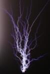
The jacobs ladder has a small gap of 1/2 inch and the top spacing is 4 inches. When it's running the arc often goes about an inch above the top of the ladders.
I'm not using irfp460 any more, I upgraded to 30N60s.
I'm going to put that bypass capacitor back on and scope it to see if that changes the waveform.
This site is powered by e107, which is released under the GNU GPL License. All work on this site, except where otherwise noted, is licensed under a Creative Commons Attribution-ShareAlike 2.5 License. By submitting any information to this site, you agree that anything submitted will be so licensed. Please read our Disclaimer and Policies page for information on your rights and responsibilities regarding this site.


 Royer circuit - blown MOSFET?