If you need assistance, please send an email to forum at 4hv dot org. To ensure your email is not marked as spam, please include the phrase "4hv help" in the subject line. You can also find assistance via IRC, at irc.shadowworld.net, room #hvcomm.
Support 4hv.org!
Donate:
4hv.org is hosted on a dedicated server. Unfortunately, this server costs and we rely on the help of site members to keep 4hv.org running. Please consider donating. We will place your name on the thanks list and you'll be helping to keep 4hv.org alive and free for everyone. Members whose names appear in red bold have donated recently. Green bold denotes those who have recently donated to keep the server carbon neutral.
Special Thanks To:
Aaron Holmes
Aaron Wheeler
Adam Horden
Alan Scrimgeour
Andre
Andrew Haynes
Anonymous000
asabase
Austin Weil
barney
Barry
Bert Hickman
Bill Kukowski
Blitzorn
Brandon Paradelas
Bruce Bowling
BubeeMike
Byong Park
Cesiumsponge
Chris F.
Chris Hooper
Corey Worthington
Derek Woodroffe
Dalus
Dan Strother
Daniel Davis
Daniel Uhrenholt
datasheetarchive
Dave Billington
Dave Marshall
David F.
Dennis Rogers
drelectrix
Dr. John Gudenas
Dr. Spark
E.TexasTesla
eastvoltresearch
Eirik Taylor
Erik Dyakov
Erlend^SE
Finn Hammer
Firebug24k
GalliumMan
Gary Peterson
George Slade
GhostNull
Gordon Mcknight
Graham Armitage
Grant
GreySoul
Henry H
IamSmooth
In memory of Leo Powning
Jacob Cash
James Howells
James Pawson
Jeff Greenfield
Jeff Thomas
Jesse Frost
Jim Mitchell
jlr134
Joe Mastroianni
John Forcina
John Oberg
John Willcutt
Jon Newcomb
klugesmith
Leslie Wright
Lutz Hoffman
Mads Barnkob
Martin King
Mats Karlsson
Matt Gibson
Matthew Guidry
mbd
Michael D'Angelo
Mikkel
mileswaldron
mister_rf
Neil Foster
Nick de Smith
Nick Soroka
nicklenorp
Nik
Norman Stanley
Patrick Coleman
Paul Brodie
Paul Jordan
Paul Montgomery
Ped
Peter Krogen
Peter Terren
PhilGood
Richard Feldman
Robert Bush
Royce Bailey
Scott Fusare
Scott Newman
smiffy
Stella
Steven Busic
Steve Conner
Steve Jones
Steve Ward
Sulaiman
Thomas Coyle
Thomas A. Wallace
Thomas W
Timo
Torch
Ulf Jonsson
vasil
Vaxian
vladi mazzilli
wastehl
Weston
William Kim
William N.
William Stehl
Wesley Venis
The aforementioned have contributed financially to the continuing triumph of 4hv.org. They are deserving of my most heartfelt thanks.
Registered Member #89
Joined: Thu Feb 09 2006, 02:40PM
Location: Zadar, Croatia
Posts: 3145
This is what I have been busy through most of last year. It is not really anything special to you guy's standards, but since it wasted me a great deal of time and since there's no chance I'll work on it anymore I really think I should have it posted.
Basically I started from this stupid idea of building my own heatsinks from aluminium sheets. At first I wanted 3mm aluminium but only got 1.5mm. For some reason I thought it would be ''just fine'' (??)
I started cutting them up and building the structure I wanted, which wasted me a lot of time again. I wanted to have entire inverter and control electronics built into something 'solid'.
At first I wanted to install a stack of fans around the edges, but small 25mm fans were too expensive and I abandoned that idea (completely ignoring the fact that there will be nearly no natural convection from what I did).
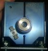
I wanted to use 2 parallel bridges of IRFP450's. In fear of parasitic oscillations I separated them completely apart the power supply. Note the odd orientations of switches: I had 4 Al plates, and I wanted the thermal contact
I used one of these coils for a secondary. Resonant frequency was around 650kHz without and 400kHz with dedicated toroid.
How I built the H bridges. Using cables to provide gate drive for each device separately proved to be a mess and a problem. Later I found out how huge difficulty is to assemble this thing together.
This is how the first assembly looked. Despite I glued them sil pads kept falling off, and I only succeeded after several attempts. Thought to have succeeded, at least. Note the weird circuit boards that I put in, they didn't last for long.
The circuit consisted of nothing but gate drivers fed directly by clamped CT output. When CT is clamped with zeners, it will put out a very good approximation of square wave since it is effectively a current source. I believed this is just OK and a test with small half-bridge coil proved that it works. I for some reason believed that simple circuit will minimize delays and be simple to debug.
The circuit is started up by a short pulse given into one of gate driver inputs at rising edge of enable signal. (enable signal was just a simple switch at that time).
Of course, after I powered everything up for a basic test, it didn't work. UC3710 gate drivers I used 2+2 in parallel seemed to shut down, latch up or whatever, for no apparent reason.
Also, since I wanted this coil to run from full wave rectified mains, with no filtering (because I did not have any filter caps) or interrupter. The problem was that even with the small coil the circuit tended to be unstable with fullwave rectified mains, tending to quit oscillation at zero cross. Some smaller filter caps helped, but then other problem appeared - if enable signal was held to 1 circuit could spontaneously start without warning, despite it didn't receive start pulse. Transients caused by applying the +325V were enough to start it.
When I tested the circuit in the big inverter I just blew mosfet's for unexplained reason.
Because of this and the first unexplained problem I started to dislike the circuit and quickly abandoned it.
My next circuit used 74HC14 and mostly antenna feedback (CT never worked with it). I wanted to use NE555 to constantly provide enable signal, as well as I switched to only 2 UC3710 gate drivers - it is completely pointless to parallel drivers in a system where currents are anyway dictated by leakage inductance of the GDT.
I tested the circuit in a small experimental coil and it worked well.
To much of my frustration, circuit didn't work again when I put the board into final setup! The UC3710's were shutting down again!
I was very confused and unable to find what problem was.
Apart from that, circuit had pitfalls (I was basically trying to send DC through the GDT, weird waveform in case oscillation fails to start, and potentially damaging to mosfet's). It also blew a mosfet in the test circuit once I tried to use it with CT instead of antenna.
Desperate, I ordered a lot of IXDD414's believing there is something wrong with UC3710 gate drivers.
The new circuit was probably the most complex thing I ever designed completely myself.
For start-up, it used a dedicated 50% duty cycle oscillator tuned close to soil's resonant frequency. The oscillator would drive the output first. As feedback signal appears, it disables the oscillator and gates itself to output. If feedback signal disappears for any reason, after 200us delay oscillator starts up again.
I used 74HC14 gates with RC networks to generate deadtime on the output.
To my huge surprise, the circuit seemed to work *excellently* in test setup.
I put the board into the big inverter, set it to oscillate at desired frequency (400kHz) and put some light bulbs onto bridge outputs.
Oddly enough, mosfets blew again.
I dismantled everything, removing the boards and putting in a single lash up air-wired H bridge. I powered it up, it seemed to work fine with a light bulb - then I switched to resonator - and witnessed some 30cm sparks! Only for few seconds, because mosfets blew again then.
And after inspecting everything very carefully, I realized only one thing can be the cause - opened the bridge, and after some inspection I found out that a sil pad is punctured by chunk of aluminium and was shorting mosfet drain to ground. I somehow failed to see it in continuity checks, and it seemed to be short or open at random.
I never changed the glued sil pads even though I've changed mosfets a lot, and god knows how long was the Al chunk in there causing problems.
It may have been there since the beginning and maybe it was the reason why the first circuit didn't work??
Anyway after assembling the coil back it worked sort of well, for a while.
I also got the second H bridge to run in parallel, for a short time, producing some 40cm sparks (not a too great improvement from a single H bridge!)
I reduced the primary turns for about sqrt2 to get the current in all mosfet's same as it was with 1 H bridge.
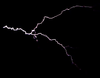
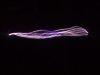
So here are some spark pics:
I think I never actually photographed the 40cm sparks I got from paralleled bridges. Sparks on the pictures are 30cm at most, still very hot.
The heatsink performed very poorly - sil pads added a huge amount of thermal resistance, and thin 1.5m aluminium conducted it poorly even if I used external convection. Run times were like 2 minutes a most!
But I didn't care, I was so excited about the sparks I got that I wanted to wrap the coil up.
I started designing various 'upgrades' like a tappable primary coil (intended to be ran with and without breakout point, for wireless power demonstrations), a remote control, proper power supply, etc.
The coil sat for few weeks, and after I was done, I powered the coil up -on my horror mosfets blew again after only few seconds of run time!
As I needed the coil for demonstration I started to panic - in debugging mania I took everything apart and put together many times, replacing sil pads, mosfets, mutilating H bridge boards, and blew like 20 mosfets trying to find what was wrong.
But I didn't.
MOSET's blew instantly, or blew fuse at some voltage level, even completely cold. Circuit was extremely hard to analyze because of it's crappy design.
Desparate, put back the lash-up bridge from beginning, which somehow worked (I have no clue why).
Replacing the mosfets was such hard work, and I could damage something every time I do it.
So the coil still sits with mock H bridge, I don't run it anymore as it can just blow any time(I never found the fault) and I'll never be bothered to replace mosfets again. It failed to meet any reasonable reliability standards.
So this is how project ended, I just messed up so hard that nothing can save it any more.
To summarize some of flaws:
-Completely silly heatsink design. I put such a hard work into it, and really failed to understand basic thermal management. The thin metal conducted heat poorly, and I had no forced air stream which is absolutely required for a heatsink in horizontal position.
The entire effort was absolutely not worth buying some CPU heatsinks or even large new heatsinks from ebay. Only explanation of why I did this was because I was an idiot.
-Sil pads are extremely poor conductors of heat probably no better than 3-4K/W and heatsink of any size is vain while they are used.
-Trying to assemble some odd sort of structure I put way too much pressure onto sil pads, which was one of reasons why they got damaged.
-mess of gate drive cables was just horrible, any of them could have easily got damaged or shorted to something.
- not enough space left for a power supply, I ended always using external one.
- extreme difficulty of changing mosfets. I was arrogant enough to think I won't do it often.
- paralleled H bridges are just unnecessary bother over using bigger mosfets. No need of complicating things, especially if mosfets are so hard to change as they were. etc.
So yes, it does spark, but after all these pitfalls, unreliability and final problem I couldn't solve I don't think I can really consider this project a success. I hope I at least learned something for my future coiling.
After I collect some money I'll start anew, but probably after resting from ''three legged fuses'' for a while.
Some older pics of lighting bulbs wirelessly:
I added some more pics of current state of the project. I have no more motivation of repairing it's full capability or doing anything more with it.
Banned on 3/17/2009. Registered Member #487
Joined: Sun Jul 09 2006, 01:22AM
Location:
Posts: 617
Well if anything, we got some entertainment out of reading about it. I think that bridges could be parallel without problems. Instead of a parallel bridge you could parallel each mostfet and have it as one bridge. I see it in designs here at work on a daily basis. They just love to parallel IRFP450's
Had some of my own weird problems lately. With that being said I have a completely unrelated tip for everyone.
NEVER RUN EARTH GROUND TRACES ON YOUR BOARDS! Works fine for power supply boards or whatever but for SSTC or DRSSTC it'll will only cause problems. Now back to cutting traces
Registered Member #1232
Joined: Wed Jan 16 2008, 10:53PM
Location: Doon tha Toon!
Posts: 881
> They just love to parallel IRFP450's
IRFP450's are cheap in high volumes. Several TO-247 devices in parallel can handle currents that would otherwise require more expensive packages.
Another paralleling option for SSTC's is to parallel complete H-bridges by feeding their outputs to a single primary coil via series inductors. These inductors help with sharing the load current between inverters, and also limit "shoot-between" currents when the two inverters are not perfectly synchronised.
The wireless power pictures are very impressive Marko. The bulb looks quite bright in those pics.
Banned on 3/17/2009. Registered Member #487
Joined: Sun Jul 09 2006, 01:22AM
Location:
Posts: 617
GeordieBoy wrote ...
.
Another paralleling option for SSTC's is to parallel complete H-bridges by feeding their outputs to a single primary coil via series inductors. These inductors help with sharing the load current between inverters, and also limit "shoot-between" currents when the two inverters are not perfectly synchronized.
-Richie,
That is another thing they do here. I have a giant PCB that was given to me by an engineer that is basically a two bridges that are paralleled and each fet in each bridge is two irfp450's paralleled for a total of 16 irfp450's all working as a single bridge or seperate or whatever. It is for an AC power supply, a very expensive one. Yes, its going to be used in a Tesla coil, eventually.
Registered Member #95
Joined: Thu Feb 09 2006, 04:57PM
Location: Norway
Posts: 1308
It's unfortunate that you're unsatisfied with something you've spent so much time on, at least you learnt something. (I hope.) Know when to call it quits next time or it'll get the better of you. I wasted a good 6 months doing nothing but play with gate driving trying to get PWM to work, it was incredibly frustrating and not very rewarding. Since then I've become impatient and quit projects if they stagnate for more than a few weeks.
Registered Member #160
Joined: Mon Feb 13 2006, 02:07AM
Location: Melbourne, Australia
Posts: 938
I don't know why you are so hard on yourself Marko. Your work is obviously not a failure even if it didn't do everything you expected it to. How much you learnt from it, I can only presume is a lot, so why the sad face? Your demonstration of wireless energy transfer is impressive, do you have any figures of power in and power received? Your workmanship is also very nice, and if you had the desire I think you could solve some of your issues creatively. Well done.
This site is powered by e107, which is released under the GNU GPL License. All work on this site, except where otherwise noted, is licensed under a Creative Commons Attribution-ShareAlike 2.5 License. By submitting any information to this site, you agree that anything submitted will be so licensed. Please read our Disclaimer and Policies page for information on your rights and responsibilities regarding this site.


 Marko's SSTC