
Marko's SSTC
Marko, Fri Jul 11 2008, 01:58PMThis is what I have been busy through most of last year. It is not really anything special to you guy's standards, but since it wasted me a great deal of time and since there's no chance I'll work on it anymore I really think I should have it posted.
Basically I started from this stupid idea of building my own heatsinks from aluminium sheets.
At first I wanted 3mm aluminium but only got 1.5mm. For some reason I thought it would be ''just fine'' (??)
I started cutting them up and building the structure I wanted, which wasted me a lot of time again. I wanted to have entire inverter and control electronics built into something 'solid'.
At first I wanted to install a stack of fans around the edges, but small 25mm fans were too expensive and I abandoned that idea (completely ignoring the fact that there will be nearly no natural convection from what I did).
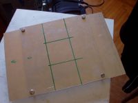
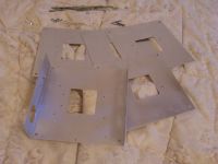
I wanted to use 2 parallel bridges of IRFP450's. In fear of parasitic oscillations I separated them completely apart the power supply. Note the odd orientations of switches: I had 4 Al plates, and I wanted the thermal contact
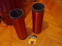
I used one of these coils for a secondary. Resonant frequency was around 650kHz without and 400kHz with dedicated toroid.
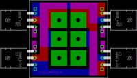
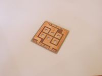
How I built the H bridges. Using cables to provide gate drive for each device separately proved to be a mess and a problem. Later I found out how huge difficulty is to assemble this thing together.
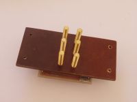
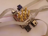
This is how the first assembly looked. Despite I glued them sil pads kept falling off, and I only succeeded after several attempts. Thought to have succeeded, at least. Note the weird circuit boards that I put in, they didn't last for long.
The circuit consisted of nothing but gate drivers fed directly by clamped CT output. When CT is clamped with zeners, it will put out a very good approximation of square wave since it is effectively a current source. I believed this is just OK and a test with small half-bridge coil proved that it works. I for some reason believed that simple circuit will minimize delays and be simple to debug.
The circuit is started up by a short pulse given into one of gate driver inputs at rising edge of enable signal. (enable signal was just a simple switch at that time).
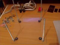
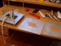
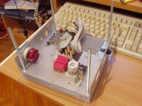
Of course, after I powered everything up for a basic test, it didn't work. UC3710 gate drivers I used 2+2 in parallel seemed to shut down, latch up or whatever, for no apparent reason.
Also, since I wanted this coil to run from full wave rectified mains, with no filtering (because I did not have any filter caps) or interrupter. The problem was that even with the small coil the circuit tended to be unstable with fullwave rectified mains, tending to quit oscillation at zero cross. Some smaller filter caps helped, but then other problem appeared - if enable signal was held to 1 circuit could spontaneously start without warning, despite it didn't receive start pulse. Transients caused by applying the +325V were enough to start it.
When I tested the circuit in the big inverter I just blew mosfet's for unexplained reason.
Because of this and the first unexplained problem I started to dislike the circuit and quickly abandoned it.
My next circuit used 74HC14 and mostly antenna feedback (CT never worked with it). I wanted to use NE555 to constantly provide enable signal, as well as I switched to only 2 UC3710 gate drivers - it is completely pointless to parallel drivers in a system where currents are anyway dictated by leakage inductance of the GDT.
I tested the circuit in a small experimental coil and it worked well.
To much of my frustration, circuit didn't work again when I put the board into final setup! The UC3710's were shutting down again!
I was very confused and unable to find what problem was.
Apart from that, circuit had pitfalls (I was basically trying to send DC through the GDT, weird waveform in case oscillation fails to start, and potentially damaging to mosfet's).
It also blew a mosfet in the test circuit once I tried to use it with CT instead of antenna.
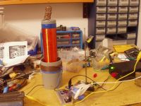
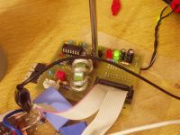
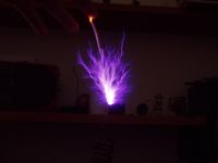
Desperate, I ordered a lot of IXDD414's believing there is something wrong with UC3710 gate drivers.
The new circuit was probably the most complex thing I ever designed completely myself.
For start-up, it used a dedicated 50% duty cycle oscillator tuned close to soil's resonant frequency. The oscillator would drive the output first. As feedback signal appears, it disables the oscillator and gates itself to output. If feedback signal disappears for any reason, after 200us delay oscillator starts up again.
I used 74HC14 gates with RC networks to generate deadtime on the output.
To my huge surprise, the circuit seemed to work *excellently* in test setup.
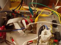
I put the board into the big inverter, set it to oscillate at desired frequency (400kHz) and put some light bulbs onto bridge outputs.
Oddly enough, mosfets blew again.
I dismantled everything, removing the boards and putting in a single lash up air-wired H bridge. I powered it up, it seemed to work fine with a light bulb - then I switched to resonator - and witnessed some 30cm sparks! Only for few seconds, because mosfets blew again then.
And after inspecting everything very carefully, I realized only one thing can be the cause - opened the bridge, and after some inspection I found out that a sil pad is punctured by chunk of aluminium and was shorting mosfet drain to ground. I somehow failed to see it in continuity checks, and it seemed to be short or open at random.
I never changed the glued sil pads even though I've changed mosfets a lot, and god knows how long was the Al chunk in there causing problems.
It may have been there since the beginning and maybe it was the reason why the first circuit didn't work??
Anyway after assembling the coil back it worked sort of well, for a while.
I also got the second H bridge to run in parallel, for a short time, producing some 40cm sparks (not a too great improvement from a single H bridge!)
I reduced the primary turns for about sqrt2 to get the current in all mosfet's same as it was with 1 H bridge.
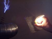
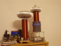
So here are some spark pics:
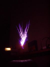
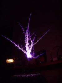
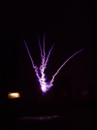
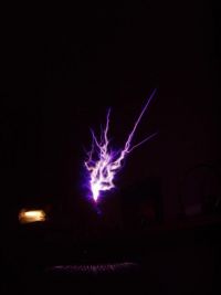
I think I never actually photographed the 40cm sparks I got from paralleled bridges. Sparks on the pictures are 30cm at most, still very hot.
The heatsink performed very poorly - sil pads added a huge amount of thermal resistance, and thin 1.5m aluminium conducted it poorly even if I used external convection. Run times were like 2 minutes a most!
But I didn't care, I was so excited about the sparks I got that I wanted to wrap the coil up.
I started designing various 'upgrades' like a tappable primary coil (intended to be ran with and without breakout point, for wireless power demonstrations), a remote control, proper power supply, etc.
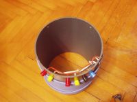
The coil sat for few weeks, and after I was done, I powered the coil up -on my horror mosfets blew again after only few seconds of run time!
As I needed the coil for demonstration I started to panic - in debugging mania I took everything apart and put together many times, replacing sil pads, mosfets, mutilating H bridge boards, and blew like 20 mosfets trying to find what was wrong.
But I didn't.
MOSET's blew instantly, or blew fuse at some voltage level, even completely cold. Circuit was extremely hard to analyze because of it's crappy design.
Desparate, put back the lash-up bridge from beginning, which somehow worked (I have no clue why).
Replacing the mosfets was such hard work, and I could damage something every time I do it.
So the coil still sits with mock H bridge, I don't run it anymore as it can just blow any time(I never found the fault) and I'll never be bothered to replace mosfets again. It failed to meet any reasonable reliability standards.
So this is how project ended, I just messed up so hard that nothing can save it any more.
To summarize some of flaws:
-Completely silly heatsink design. I put such a hard work into it, and really failed to understand basic thermal management. The thin metal conducted heat poorly, and I had no forced air stream which is absolutely required for a heatsink in horizontal position.
The entire effort was absolutely not worth buying some CPU heatsinks or even large new heatsinks from ebay. Only explanation of why I did this was because I was an idiot.
-Sil pads are extremely poor conductors of heat probably no better than 3-4K/W and heatsink of any size is vain while they are used.
-Trying to assemble some odd sort of structure I put way too much pressure onto sil pads, which was one of reasons why they got damaged.
-mess of gate drive cables was just horrible, any of them could have easily got damaged or shorted to something.
- not enough space left for a power supply, I ended always using external one.
- extreme difficulty of changing mosfets. I was arrogant enough to think I won't do it often.
- paralleled H bridges are just unnecessary bother over using bigger mosfets. No need of complicating things, especially if mosfets are so hard to change as they were. etc.
So yes, it does spark, but after all these pitfalls, unreliability and final problem I couldn't solve I don't think I can really consider this project a success.
I hope I at least learned something for my future coiling.
After I collect some money I'll start anew, but probably after resting from ''three legged fuses'' for a while.
Some older pics of lighting bulbs wirelessly:
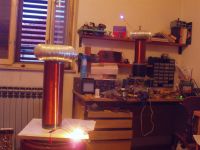
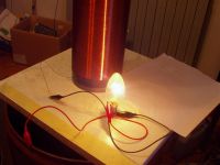
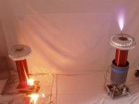
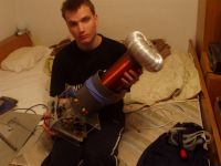
I added some more pics of current state of the project.
I have no more motivation of repairing it's full capability or doing anything more with it.
Hope you enjoy the pics. Thanks for reading!
Re: Marko's SSTC
Tom540, Fri Jul 11 2008, 08:27PM
Well if anything, we got some entertainment out of reading about it. I think that bridges could be parallel without problems. Instead of a parallel bridge you could parallel each mostfet and have it as one bridge. I see it in designs here at work on a daily basis. They just love to parallel IRFP450's
Had some of my own weird problems lately. With that being said I have a completely unrelated tip for everyone.
NEVER RUN EARTH GROUND TRACES ON YOUR BOARDS! Works fine for power supply boards or whatever but for SSTC or DRSSTC it'll will only cause problems. Now back to cutting traces

Re: Marko's SSTC
Experimentonomen, Fri Jul 11 2008, 08:40PM
Atleast we got to know what u look like
Experimentonomen, Fri Jul 11 2008, 08:40PM
Atleast we got to know what u look like

Re: Marko's SSTC
GeordieBoy, Fri Jul 11 2008, 09:52PM
> They just love to parallel IRFP450's
IRFP450's are cheap in high volumes. Several TO-247 devices in parallel can handle currents that would otherwise require more expensive packages.
Another paralleling option for SSTC's is to parallel complete H-bridges by feeding their outputs to a single primary coil via series inductors. These inductors help with sharing the load current between inverters, and also limit "shoot-between" currents when the two inverters are not perfectly synchronised.
The wireless power pictures are very impressive Marko. The bulb looks quite bright in those pics.
-Richie,
Re: Marko's SSTC
Tom540, Fri Jul 11 2008, 10:49PM
That is another thing they do here. I have a giant PCB that was given to me by an engineer that is basically a two bridges that are paralleled and each fet in each bridge is two irfp450's paralleled for a total of 16 irfp450's all working as a single bridge or seperate or whatever. It is for an AC power supply, a very expensive one. Yes, its going to be used in a Tesla coil, eventually.
Tom540, Fri Jul 11 2008, 10:49PM
GeordieBoy wrote ...
.
Another paralleling option for SSTC's is to parallel complete H-bridges by feeding their outputs to a single primary coil via series inductors. These inductors help with sharing the load current between inverters, and also limit "shoot-between" currents when the two inverters are not perfectly synchronized.
-Richie,
That is another thing they do here. I have a giant PCB that was given to me by an engineer that is basically a two bridges that are paralleled and each fet in each bridge is two irfp450's paralleled for a total of 16 irfp450's all working as a single bridge or seperate or whatever. It is for an AC power supply, a very expensive one. Yes, its going to be used in a Tesla coil, eventually.

Re: Marko's SSTC
GeordieBoy, Fri Jul 11 2008, 11:16PM
You work for Sorensen/Elgar yeah? Out of curiosity what is the power rating of the product with the twin'ed bridges using 16x 450's ?
I'd imagine it will make a great CW driver for a coil. Particularly if you can get your hands on the active PFC front-end too :)
-Richie,
Re: Marko's SSTC
uzzors2k, Sat Jul 12 2008, 05:24AM
It's unfortunate that you're unsatisfied with something you've spent so much time on, at least you learnt something. (I hope.) Know when to call it quits next time or it'll get the better of you. I wasted a good 6 months doing nothing but play with gate driving trying to get PWM to work, it was incredibly frustrating and not very rewarding. Since then I've become impatient and quit projects if they stagnate for more than a few weeks.
Re: Marko's SSTC
Steve Conner, Sat Jul 12 2008, 10:05AM
For a "failed" SSTC, I'd say that one worked quite well :)
Steve Conner, Sat Jul 12 2008, 10:05AM
For a "failed" SSTC, I'd say that one worked quite well :)
Re: Marko's SSTC
Dalus, Sat Jul 12 2008, 11:20AM
Maybe I'll try to parallel two full bridges of 40N60 igbt's in my new DRSSTC. Hope that a split MMC arrangement will work
Dalus, Sat Jul 12 2008, 11:20AM
Maybe I'll try to parallel two full bridges of 40N60 igbt's in my new DRSSTC. Hope that a split MMC arrangement will work
Re: Marko's SSTC
Coronafix, Sat Jul 12 2008, 11:37AM
I don't know why you are so hard on yourself Marko. Your work is obviously not a failure even if it didn't do everything you expected it to. How much you learnt from it, I can only presume is a lot, so why the sad face? Your demonstration of wireless energy transfer is impressive, do you have any figures of power in and power received? Your workmanship is also very nice, and if you had the desire I think you could solve some of your issues creatively.
Well done.
Re: Marko's SSTC
Marko, Sun Jul 13 2008, 05:10PM
thanks guys for trying to solace me, but I really consider this one lost. It's much better idea to spend time on something else.
Paralleling mosfets directly was my initial intention but then Richie Burnett scared me with stories about parasitic oscillations. So I went the hard way.
You guys may have not realized that I still *don't know* why the coil kept dying. After it worked flawlessly for a month, after some minor upgrades (remote control, tappable primary) it started dying instantly.
It continued dying even after those upgrades were removed, and debugging was extremely hard due to idiotic construction.
I don't know why it suddenly worked after I placed a single bridge in instead of previous two.
Actually, that single one blew once too for no apparent reason.
I never got to measure efficiency properly because coil never had the chance to run without breakout point.
In debugging mania I removed the additional primary winding that was intended to be used to run without streamer load, and never put it back as I was too scared to run without spark anyway.
I just demonstrated it with the spark, at 1..1.5meters I probably pumped like 150W at most while coil was drawing like a 1 kW+. Really just a showpiece and no practical use.
Well, I had many SSTC's that ''worked quite well'', which consisted of alligator clips and breadboarded circuits dragged across the table - none of which lived for long.
I hoped to have something more permanent, but I didn't even after all the work.
Marko, Sun Jul 13 2008, 05:10PM
thanks guys for trying to solace me, but I really consider this one lost. It's much better idea to spend time on something else.
Well if anything, we got some entertainment out of reading about it. I think that bridges could be parallel without problems. Instead of a parallel bridge you could parallel each mostfet and have it as one bridge. I see it in designs here at work on a daily basis. They just love to parallel IRFP450's
Paralleling mosfets directly was my initial intention but then Richie Burnett scared me with stories about parasitic oscillations. So I went the hard way.
You guys may have not realized that I still *don't know* why the coil kept dying. After it worked flawlessly for a month, after some minor upgrades (remote control, tappable primary) it started dying instantly.
It continued dying even after those upgrades were removed, and debugging was extremely hard due to idiotic construction.
I don't know why it suddenly worked after I placed a single bridge in instead of previous two.
Actually, that single one blew once too for no apparent reason.
do you have any figures of power in and power received? Your workmanship is also very nice, and if you had the desire I think you could solve some of your issues creatively.
I never got to measure efficiency properly because coil never had the chance to run without breakout point.
In debugging mania I removed the additional primary winding that was intended to be used to run without streamer load, and never put it back as I was too scared to run without spark anyway.
I just demonstrated it with the spark, at 1..1.5meters I probably pumped like 150W at most while coil was drawing like a 1 kW+. Really just a showpiece and no practical use.
For a "failed" SSTC, I'd say that one worked quite well :)
Well, I had many SSTC's that ''worked quite well'', which consisted of alligator clips and breadboarded circuits dragged across the table - none of which lived for long.
I hoped to have something more permanent, but I didn't even after all the work.
Re: Marko's SSTC
Tom540, Mon Jul 14 2008, 06:07PM
Hi Ritchie,
Yes I work for Elgar but we are called Xantrex now. Which is the reason I am looking for a new job. Xantrex is a mess and I am tired of working on fixing thier shitty documentation instead of doing real work. They also screwed up by ditching the Elgar name for Xantrex. Anyway.....
It goes from 1700 to 21kVA. Its and AC power supply and it uses three of the 16 FET modules. You can put a DC bias and do all kinds of weird things with the output wave form. Arbitrary waveforms as well. Here's a link to the supply.

So I have one of the amp modules. Ive been trying to get my hands on a working PFC boost converter board to power it. Then I can try paralleling the bridges. I have a ton of these fixed voltage switchers I might use on it instead.
-Tom
Tom540, Mon Jul 14 2008, 06:07PM
GeordieBoy wrote ...
You work for Sorensen/Elgar yeah? Out of curiosity what is the power rating of the product with the twin'ed bridges using 16x 450's ?
I'd imagine it will make a great CW driver for a coil. Particularly if you can get your hands on the active PFC front-end too :)
-Richie,
You work for Sorensen/Elgar yeah? Out of curiosity what is the power rating of the product with the twin'ed bridges using 16x 450's ?
I'd imagine it will make a great CW driver for a coil. Particularly if you can get your hands on the active PFC front-end too :)
-Richie,
Hi Ritchie,
Yes I work for Elgar but we are called Xantrex now. Which is the reason I am looking for a new job. Xantrex is a mess and I am tired of working on fixing thier shitty documentation instead of doing real work. They also screwed up by ditching the Elgar name for Xantrex. Anyway.....
It goes from 1700 to 21kVA. Its and AC power supply and it uses three of the 16 FET modules. You can put a DC bias and do all kinds of weird things with the output wave form. Arbitrary waveforms as well. Here's a link to the supply.

So I have one of the amp modules. Ive been trying to get my hands on a working PFC boost converter board to power it. Then I can try paralleling the bridges. I have a ton of these fixed voltage switchers I might use on it instead.
-Tom
Re: Marko's SSTC
GeordieBoy, Mon Jul 14 2008, 07:07PM
Wow, 21kVA! I shudder to think how much that weighs! I've got one of the little Elgar CW supplies here and I can just about lift that off the floor without putting my back out! I'm guessing the new stuff doesn't have the iron transformer though if you can put DC on the output! It's all clever stuff, and interesting too - thanks for the link.
-Richie,
Re: Marko's SSTC
Tom540, Mon Jul 14 2008, 08:26PM

Tom540, Mon Jul 14 2008, 08:26PM
GeordieBoy wrote ...
Wow, 21kVA! I shudder to think how much that weighs! I've got one of the little Elgar CW supplies here and I can just about lift that off the floor without putting my back out! I'm guessing the new stuff doesn't have the iron transformer though if you can put DC on the output! It's all clever stuff, and interesting too - thanks for the link.
-Richie,
No the monster one doesn't have that big fat iron core tranny. Its not a very new design. The boards are all through hole components. There is a lot of boards and separate assemblies that go into that thing. That supply weighs a ton! Never attempted to lift one but the part I have is pretty heavy. It also costs around 18k too! We don't even get discounts. Wow, 21kVA! I shudder to think how much that weighs! I've got one of the little Elgar CW supplies here and I can just about lift that off the floor without putting my back out! I'm guessing the new stuff doesn't have the iron transformer though if you can put DC on the output! It's all clever stuff, and interesting too - thanks for the link.
-Richie,

Re: Marko's SSTC
Dr. Drone, Thu Jul 17 2008, 12:57AM

Dr. Drone, Thu Jul 17 2008, 12:57AM

Re: Marko's SSTC
Marko, Thu Jul 17 2008, 01:37AM
Hi Dr. Spark, thanks for kind words
Really this one is dead now for like 2 months, and now I began construction of a completely new inverter (much easier than bothering with the thing in this thread) that may be used to drive a SSTC at some point.
Even if I could fix the first one I think it's not right to waste any more time on it.
I've decided that's really better and more practical to have a box with all non-tesla-coil components which I can connect to anything around I want. I've seen people building DRSSTC's in that manner and it seems very practical, plus I'll correct all my mistakes so far.
Changing the PCB's I could even use the inverter for something else like induction heater.
Need though to gather some parts and hope the temperature to drop somewhat so I can work in the garage at all.
Marko, Thu Jul 17 2008, 01:37AM
Dr. Spark wrote ...
Hi Marko,
First your have big balls @ to post “FAILEDâ€
Second, your documentation is stupendous! Good work!
Third, I am always working on 3 or 4 coils at the same time as get pissed and roll one in corner. Coming back later gives me new energy and sometimes looking at a problem over and over again, you will miss something. Take a break for a few months. I am just now ready to hit the Quad VTTC again after Dr. H post.
May I make a few suggestions? Wind a new primary with a bunch of turns to lower the stress on the FET’s. You can always reduce windings giving you more power once things are stable. Also put some space between the turns @ .
.
Feedback, feedback, feedback. You be surprised how much the fo will change
from day to day on a little secondary. Just moving your hand can make a fo shift big time. If the coil is not 100% in tune, the primary will fight the FETs.
Do some FA on the FET’s, that is open one up and look at the die. What is blown? This will allow you to focus on that area like if the gate, look at the over shoot, etc. Use a Dremel tool and take it down in layers. We use rocket fuel (red stuff they mix with O2) to dissolve the plastic. One drop and die is exposed but maybe hard to get.
Good luck, I am sure all will work out if you just take a break.
Cheers,
Ch
Hi Marko,
First your have big balls @
 to post “FAILEDâ€
to post “FAILED†Second, your documentation is stupendous! Good work!
Third, I am always working on 3 or 4 coils at the same time as get pissed and roll one in corner. Coming back later gives me new energy and sometimes looking at a problem over and over again, you will miss something. Take a break for a few months. I am just now ready to hit the Quad VTTC again after Dr. H post.
May I make a few suggestions? Wind a new primary with a bunch of turns to lower the stress on the FET’s. You can always reduce windings giving you more power once things are stable. Also put some space between the turns @
 .
.Feedback, feedback, feedback. You be surprised how much the fo will change
from day to day on a little secondary. Just moving your hand can make a fo shift big time. If the coil is not 100% in tune, the primary will fight the FETs.
Do some FA on the FET’s, that is open one up and look at the die. What is blown? This will allow you to focus on that area like if the gate, look at the over shoot, etc. Use a Dremel tool and take it down in layers. We use rocket fuel (red stuff they mix with O2) to dissolve the plastic. One drop and die is exposed but maybe hard to get.
Good luck, I am sure all will work out if you just take a break.
Cheers,
Ch
Hi Dr. Spark, thanks for kind words

Really this one is dead now for like 2 months, and now I began construction of a completely new inverter (much easier than bothering with the thing in this thread) that may be used to drive a SSTC at some point.
Even if I could fix the first one I think it's not right to waste any more time on it.
I've decided that's really better and more practical to have a box with all non-tesla-coil components which I can connect to anything around I want. I've seen people building DRSSTC's in that manner and it seems very practical, plus I'll correct all my mistakes so far.
Changing the PCB's I could even use the inverter for something else like induction heater.
Need though to gather some parts and hope the temperature to drop somewhat so I can work in the garage at all.
Re: Marko's SSTC
Mates, Fri Jul 18 2008, 09:37PM
Dear Marko,
I was full of expectation about your wireless project and remember your notes about some troubles with your SSTC. Now the things are clear… It is a bit ironic that you, a man giving usually most complex and most funded advices and comments failed with H-bridge SSTC – a piece of cake for some of the other members. To make things a bit easier for you, I destroyed my IRFP450 half bridge immediately I plugged it in…I realized that for my crappy designs I need much more robust transistors, mainly higher voltage ratings. No more IRF450 in my live and it is much easier life now…
I wish you good luck with your next design, remember to put your transistors straight (no beds) on FAT piece of aluminum. And keep us updated about your “Marco wireless†progresses

Re: Marko's SSTC
Marko, Sat Jul 26 2008, 12:55AM
Hi,
my pc is dead so I'll be online less, but thanks for kind words in any case guys.
Hm, no higher voltage ratings are needed for me as I run only from rectified mains for now. I may use 3 phase power and 1200V IGBT's but only in distant future if everything goes right.
I believe IRFP450's are actually rather solid devices, and I believe they can process lots of power if heatsunking can statisfy their maximum dissipation.
Isolated heatsinks with direct clamp mounting are absolute must if I want to push the devices to end of their rating.
In H bridge each device sees the laod current only half of time so RMS current can effectively be 2x larger than device rating.
If I can get 8 amps at 100C it's still theoretically 5200VA at 325V or 3680VA at 230V (fullwave rectified without filtering). Not sure how much kVA could I get in reality though, and considering SSTC's circulate lots of reactive power the actual real power put into may be some 1500W - but I'd be very happy with that if it could work in reality.
Even more would be possible if voltage is pushed further than mains.
I have started building a new inverter, and would really want to finish it this summer. Going to do the initial work with IRFP450's and only switch to bigger mosfets after the first fail after being pushed *to the end*.
Marko
Marko, Sat Jul 26 2008, 12:55AM
Hi,
my pc is dead so I'll be online less, but thanks for kind words in any case guys.
I was full of expectation about your wireless project and remember your notes about some troubles with your SSTC. Now the things are clear… It is a bit ironic that you, a man giving usually most complex and most funded advices and comments failed with H-bridge SSTC – a piece of cake for some of the other members. To make things a bit easier for you, I destroyed my IRFP450 half bridge immediately I plugged it in…I realized that for my crappy designs I need much more robust transistors, mainly higher voltage ratings. No more IRF450 in my live and it is much easier life now…
Hm, no higher voltage ratings are needed for me as I run only from rectified mains for now. I may use 3 phase power and 1200V IGBT's but only in distant future if everything goes right.
I believe IRFP450's are actually rather solid devices, and I believe they can process lots of power if heatsunking can statisfy their maximum dissipation.
Isolated heatsinks with direct clamp mounting are absolute must if I want to push the devices to end of their rating.
In H bridge each device sees the laod current only half of time so RMS current can effectively be 2x larger than device rating.
If I can get 8 amps at 100C it's still theoretically 5200VA at 325V or 3680VA at 230V (fullwave rectified without filtering). Not sure how much kVA could I get in reality though, and considering SSTC's circulate lots of reactive power the actual real power put into may be some 1500W - but I'd be very happy with that if it could work in reality.
Even more would be possible if voltage is pushed further than mains.
I have started building a new inverter, and would really want to finish it this summer. Going to do the initial work with IRFP450's and only switch to bigger mosfets after the first fail after being pushed *to the end*.
Marko
Re: Marko's SSTC
GeordieBoy, Sat Jul 26 2008, 01:41AM
> In H bridge each device sees the load current only half of time so RMS current can effectively be 2x larger than device rating.
No. The RMS calculation already takes the waveshape into account Marko. It automatically allows for the fact that the current is a half-sinusoid in shape or whatever weird shape the current waveform through a given device happens to be. The RMS current basically tells you the "equivalent DC resistive heating current."
If the device is rated for 8 amps RMS at 100'c junction temperature, that means it is spec'ed to carry a drain current of 8 amps RMS whatever the waveshape.
For what it's worth if an inverter's load current is perfectly sinusoidal, then the peak current can be increased by 41% if only alternate half-cycles are conducted instead of the whole sinewave. This keeps the same RMS current value. It might seem suprising that this is not a factor of two improvement since current is now only flowing for half of the previous time. The average load current does indeed half, but remember that resistive heating is proportional to I squared. That's why the permisable increase in peak current is sqrt(2) and not 2. The RMS calculation takes this into account in its root mean and sqaure operations.
-Richie,
Print this page