If you need assistance, please send an email to forum at 4hv dot org. To ensure your email is not marked as spam, please include the phrase "4hv help" in the subject line. You can also find assistance via IRC, at irc.shadowworld.net, room #hvcomm.
Support 4hv.org!
Donate:
4hv.org is hosted on a dedicated server. Unfortunately, this server costs and we rely on the help of site members to keep 4hv.org running. Please consider donating. We will place your name on the thanks list and you'll be helping to keep 4hv.org alive and free for everyone. Members whose names appear in red bold have donated recently. Green bold denotes those who have recently donated to keep the server carbon neutral.
Special Thanks To:
Aaron Holmes
Aaron Wheeler
Adam Horden
Alan Scrimgeour
Andre
Andrew Haynes
Anonymous000
asabase
Austin Weil
barney
Barry
Bert Hickman
Bill Kukowski
Blitzorn
Brandon Paradelas
Bruce Bowling
BubeeMike
Byong Park
Cesiumsponge
Chris F.
Chris Hooper
Corey Worthington
Derek Woodroffe
Dalus
Dan Strother
Daniel Davis
Daniel Uhrenholt
datasheetarchive
Dave Billington
Dave Marshall
David F.
Dennis Rogers
drelectrix
Dr. John Gudenas
Dr. Spark
E.TexasTesla
eastvoltresearch
Eirik Taylor
Erik Dyakov
Erlend^SE
Finn Hammer
Firebug24k
GalliumMan
Gary Peterson
George Slade
GhostNull
Gordon Mcknight
Graham Armitage
Grant
GreySoul
Henry H
IamSmooth
In memory of Leo Powning
Jacob Cash
James Howells
James Pawson
Jeff Greenfield
Jeff Thomas
Jesse Frost
Jim Mitchell
jlr134
Joe Mastroianni
John Forcina
John Oberg
John Willcutt
Jon Newcomb
klugesmith
Leslie Wright
Lutz Hoffman
Mads Barnkob
Martin King
Mats Karlsson
Matt Gibson
Matthew Guidry
mbd
Michael D'Angelo
Mikkel
mileswaldron
mister_rf
Neil Foster
Nick de Smith
Nick Soroka
nicklenorp
Nik
Norman Stanley
Patrick Coleman
Paul Brodie
Paul Jordan
Paul Montgomery
Ped
Peter Krogen
Peter Terren
PhilGood
Richard Feldman
Robert Bush
Royce Bailey
Scott Fusare
Scott Newman
smiffy
Stella
Steven Busic
Steve Conner
Steve Jones
Steve Ward
Sulaiman
Thomas Coyle
Thomas A. Wallace
Thomas W
Timo
Torch
Ulf Jonsson
vasil
Vaxian
vladi mazzilli
wastehl
Weston
William Kim
William N.
William Stehl
Wesley Venis
The aforementioned have contributed financially to the continuing triumph of 4hv.org. They are deserving of my most heartfelt thanks.
Registered Member #95
Joined: Thu Feb 09 2006, 04:57PM
Location: Norway
Posts: 1308
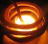
I've been playing with somewhat more powerful induction heater over the last few days, and when attempting to heat various work pieces I noticed I couldn't get a coin to sit still. The coin is 75% copper, 25% nickel, otherwise known as a Norwegian enkroning. It was perched atop a bolt, and when I tuned for resonance it would jump off. I've just made a Rube Goldberg machine! Video. This shows how much current there is circulating in the work piece!
Anyway now that I got your attention I can ask a quick question. What kind of coupling do I want in an LCLR induction heater? As high as possible? I'm using incredibly low coupling right now and I don't seem to be getting anywhere near the power transfer I expected. At the same time I've found large work pieces damp the work coil current so much that it hardly heats anymore, and with no load the current drawn from the inverter sky-rockets. So will higher coupling damp the resonance so much that it stops heating? Or can I increase the coupling, reduce the matching inductance, and never run it without a work piece anymore?
Registered Member #1232
Joined: Wed Jan 16 2008, 10:53PM
Location: Doon tha Toon!
Posts: 881
Re The rotation of the workpiece. You ideally want high-coupling between the IH coil and the workpiece. If un-constrained a coil will rotate in such a way that it minimises it's cross-section that couples with the magnetic field lines. Essentially it will stand on edge and stay relatively cool because only a very thin cross-section cuts the field.
As you discovered the power transfer is highly dependant on the coupling factor and the damping that a particular workpiece creates (Q-factor) when inserted into the work coil.
It is unlikely you will find one combination of work-coil and impedance matching components that will allow you to heat a variety of different materials and sizes of workpiece satisfactorily without adjustment! That is why real induction heating setups almost always have the work coil made specifically for the job in hand, and there are hundreds of different coils. Even then they still allow a component in the matching network (such as the L part of L-match network) or a transformer tap to be changed to suit different loadings.
Current draw from the inverter increases when there is no workpiece present because the tank Q tends towards infinity and you must be tracking the resonant frequency. What you really want to do is sense the work-coil current and control the inverter frequency in such a way to keep the work-coil current constant. With this control in place, the work-coil current (and cap current) will not sky-rocket to dangerous levels if the workpiece is removed. Since Q factor increases as the workpiece is removed the actual power supplied by the inverter to maintain a specified work-coil current decreases. If you get the coupling and control right, you can expect the line-current draw to increase noticeably when you insert a workpiece into a previously empty coil.
Registered Member #95
Joined: Thu Feb 09 2006, 04:57PM
Location: Norway
Posts: 1308
It makes sense now Richie, thanks. I've only been monitoring the current drawn from the inverter and forgot that the tank current behaves differently. It would take some fancy control circuit to do constant current control by frequency given how the LCLR responds, I'll have to see about that one. I just wonder how it would behave since once it passes to the wrong side of the frequency hump everything becomes inverted. As long you don't try regulating the current too high, and thus force the circuit to lower the frequency over to the capacitive region it should remain stable I think.
Tonskulus, I saw your video this morning actually. Are you using Kim's circuit?
Registered Member #1223
Joined: Thu Jan 10 2008, 04:32PM
Location:
Posts: 133
Uzzors wrote ...
Tonskulus, I saw your video this morning actually. Are you using Kim's circuit?
Yes, it is almost like kim's circuit but there are some different solutions anyway. Basic circuit is the same. It seems to be reliable so I don't see any point about making it more complex. My system has also system that keeps input current constant. Like 20Amps or so, what ever I want it to be. It is not active forward converter, it is just automatic L-match adjusting system (Ferrite core is moved by solenoid).
Registered Member #1232
Joined: Wed Jan 16 2008, 10:53PM
Location: Doon tha Toon!
Posts: 881
Hi Uzzors,
You always want the inverter driving on the high side of the LCLR network's pole frequency (maxiumum power point.) This ensures ZVS of the switches under all load conditions. And ideally at very high power you would like the operating frequency optimised to be somewhere close to this resonant frequency so that the power devices don't have to interrupt too much current. In a rough "one size fits all" DIY design, this won't be the case though.
As it shows on my IH web page, power control can be achieved in many ways. Varying the drive frequency is just one method. (A controlled thyristor bridge to vary the DC bus voltage is another common technique.)
In the variable-frequency case you have two control loops: one that tracks the resonant frequency, and one that controls the power level. The strategy is basically as follows:
Start with a high drive frequency and sweep the drive frequency down until EITHER the requested work coil current is reached _OR_ the resonant frequency of the LCLR network is reached (maximum power point). If the resonant frequency is reached first, and the power throughput at this point is way too low, then the matching inductor or coupling needs to be changed to get more power throughput. Most commercial heaters will indicate this as a tap change required inside the heat station.
If you use a VCO, there are basically too things that can "increase" its running frequency. If the phase angle between tank voltage and inverter voltage is less than 90 degrees, or if the tank current (or tank voltage) is greater than requested. Whichever one of these criteria that dictates the highest operating frequency is the one that wins the battle and takes control of the VCO at that moment.
So for example, if there is no workpiece installed tank circuit Q is very high and the power control loop will push the operating frequency right up to keep the work-coil current under control. As a lossy workpiece is added, the Q-falls. The power control loop will request progressively lower frequencies in order to maintain the requested work-coil current as the Q decreases. Power sourced by the inverter will increase and become more in-phase as the resonant frequency of the LCLR network is approached. Eventually the resonant frequency of the LCLR network is reached by the VCO and the tank circuit voltage lags inverter output voltage by 90 degrees. Adding further load to the workcoil will cause the frequency tracking loop to take over. This will act to keep the VCO operating at the resonant frequency where maximum power is delivered as the properties of the workpiece alter the resonant frequency of the tank circuit. If we quickly remove a lossy workpiece from the workcoil, the power control loop will instantly take control again and the drive frequency will shoot up to stop the tank current going sky high due to excessive Q.
Registered Member #95
Joined: Thu Feb 09 2006, 04:57PM
Location: Norway
Posts: 1308
Tonskulus wrote ...
Yes, it is almost like kim's circuit but there are some different solutions anyway. Basic circuit is the same. It seems to be reliable so I don't see any point about making it more complex. My system has also system that keeps input current constant. Like 20Amps or so, what ever I want it to be. It is not active forward converter, it is just automatic L-match adjusting system (Ferrite core is moved by solenoid).
Mechanical current control? Have you posted your heater in the projects section yet, or did I miss it?
I've made a preliminary circuit which needs a sanity check. I expect there are flaws in the phase comparator section since I don't quite understand how it works. First the soft start which ensures the VCO starts at max freq. In the meantime the tank voltage rises and is stepped down and averaged, later compared to what the safe value is. Error is feed into the VCO. The phase comparator does what it does...
Registered Member #1232
Joined: Wed Jan 16 2008, 10:53PM
Location: Doon tha Toon!
Posts: 881
Uzzors, conceptually your schematic looks fine - It includes all the important elements. There are a few things that you might need to change though:
1. There should be a pull-down resistor at the VCO control voltage input pin after the point where the control signals are OR'ed together with the signal diodes, (pin 9.)
2. You will also need some kind of pull-down, and possibly and amplifier or clamp on the tank-voltage sense line feeding into the phase comparator (pin 14.)
3. The other input to the phase comparator should come from the inverter output voltage. Without looking at the PLL datasheet i'd guess that it's currently coming from the VCO output instead.
4. You might need some compensation components around the error amplifier that senses and controls peak tank circuit voltage. At the moment the loop gain and bandwidth will be very high so it may oscillate wildly instead of smoothly and quickly settling to the power level you request.
5. The analogue "soft-start" circuit you show might need a diode across the resistor to quickly reset it if you turn the power off and back on again. If you wind up supply voltage slowly with a variac (or have soft-start on the DC bus, you can probably do away with this part, and the over-current detect should be fast enough to catch it anyway.)
6. You might need to buffer the output from the PLL loop-filter to prevent it's response being messed up by the diodes and pull-down resistor that follow the loop filter.
7. You will have to choose the resistors on pins 11 and 12 so the VCO runs over a suitable range. You don't want it to start at a frequency that is too high and damages the power electronics, due to improper gate-drive etc.
At this point I should also say that Steve C has reported good success with a similar (but possibly simpler) PLL based controller for induction heating. However his design is very close (if not identical?) to what he used to control a DRSSTC. In a similar way to current limiting in a DRSSTC it achieves control over induction heating current by turning off the drive for a few cycles when the current gets too high. This may be "closer to home" for those familar with DRSSTC operation and apparently worked well.
Registered Member #30
Joined: Fri Feb 03 2006, 10:52AM
Location: Glasgow, Scotland
Posts: 6706
Yes, I just used one of my Mk2 DRSSTC drivers without any mods. The current limiter provided a kind of rough power control, and a variac did the rest.
The only drawback I found was that the PLL sometimes wouldn't lock by itself when DC bus voltage was applied. It needed a poke at the tuning pot to nudge it into lock. I think this was a Catch-22 situation: if the frequency started far enough away from resonance, it couldn't develop enough tank current to get any feedback signal. I've seen a sweep oscillator used in other applications to break vicious circles like these. It basically flaps the VCO frequency around until it locks.
I also used the series resonant setup, just because I like it more than the LCLR. I don't know how my driver would behave with an LCLR.
Connecting the phase comparator straight to the VCO output is a cheap and nasty shortcut, and I'm to blame for promoting it, since I've always done it in every PLL circuit I've published. The only advantage of it is to avoid the hassle of high-speed isolation circuitry for sensing the inverter output voltage.
I tried making a "bucking coil" like Tonskulus described, and was just able to levitate some pieces of aluminium. I had the current limiter disabled and the variac turned right up to 270V, and it was all going fine until the levitating workpiece melted, went unstable and fell out of the coil. You can probably guess what happened next
This site is powered by e107, which is released under the GNU GPL License. All work on this site, except where otherwise noted, is licensed under a Creative Commons Attribution-ShareAlike 2.5 License. By submitting any information to this site, you agree that anything submitted will be so licensed. Please read our Disclaimer and Policies page for information on your rights and responsibilities regarding this site.


 Induction heater as an induction launcher (now with control circuit discussion!)


 Have you posted your heater in the projects section yet, or did I miss it?

