If you need assistance, please send an email to forum at 4hv dot org. To ensure your email is not marked as spam, please include the phrase "4hv help" in the subject line. You can also find assistance via IRC, at irc.shadowworld.net, room #hvcomm.
Support 4hv.org!
Donate:
4hv.org is hosted on a dedicated server. Unfortunately, this server costs and we rely on the help of site members to keep 4hv.org running. Please consider donating. We will place your name on the thanks list and you'll be helping to keep 4hv.org alive and free for everyone. Members whose names appear in red bold have donated recently. Green bold denotes those who have recently donated to keep the server carbon neutral.
Special Thanks To:
Aaron Holmes
Aaron Wheeler
Adam Horden
Alan Scrimgeour
Andre
Andrew Haynes
Anonymous000
asabase
Austin Weil
barney
Barry
Bert Hickman
Bill Kukowski
Blitzorn
Brandon Paradelas
Bruce Bowling
BubeeMike
Byong Park
Cesiumsponge
Chris F.
Chris Hooper
Corey Worthington
Derek Woodroffe
Dalus
Dan Strother
Daniel Davis
Daniel Uhrenholt
datasheetarchive
Dave Billington
Dave Marshall
David F.
Dennis Rogers
drelectrix
Dr. John Gudenas
Dr. Spark
E.TexasTesla
eastvoltresearch
Eirik Taylor
Erik Dyakov
Erlend^SE
Finn Hammer
Firebug24k
GalliumMan
Gary Peterson
George Slade
GhostNull
Gordon Mcknight
Graham Armitage
Grant
GreySoul
Henry H
IamSmooth
In memory of Leo Powning
Jacob Cash
James Howells
James Pawson
Jeff Greenfield
Jeff Thomas
Jesse Frost
Jim Mitchell
jlr134
Joe Mastroianni
John Forcina
John Oberg
John Willcutt
Jon Newcomb
klugesmith
Leslie Wright
Lutz Hoffman
Mads Barnkob
Martin King
Mats Karlsson
Matt Gibson
Matthew Guidry
mbd
Michael D'Angelo
Mikkel
mileswaldron
mister_rf
Neil Foster
Nick de Smith
Nick Soroka
nicklenorp
Nik
Norman Stanley
Patrick Coleman
Paul Brodie
Paul Jordan
Paul Montgomery
Ped
Peter Krogen
Peter Terren
PhilGood
Richard Feldman
Robert Bush
Royce Bailey
Scott Fusare
Scott Newman
smiffy
Stella
Steven Busic
Steve Conner
Steve Jones
Steve Ward
Sulaiman
Thomas Coyle
Thomas A. Wallace
Thomas W
Timo
Torch
Ulf Jonsson
vasil
Vaxian
vladi mazzilli
wastehl
Weston
William Kim
William N.
William Stehl
Wesley Venis
The aforementioned have contributed financially to the continuing triumph of 4hv.org. They are deserving of my most heartfelt thanks.
Registered Member #46012
Joined: Thu May 01 2014, 12:54AM
Location:
Posts: 20
Hi! I finished build UD 2.5B board two days ago. But have no idea how to start use it. I feel lack of documentations for people like me (I spent only one day to build it but it's my first experience wirh DRSSTC and with UD 2.x drivers). already have expirience with sstc and tube coils. I have 2ch oscilloscope, multimeter and regulated power adapter 5-35V and fixed voltage 60 and 120 V (500W) power supply. Also I have gate from this schema DRSSTC3.
Can you kindly assist me to start as safe as possible (don't damage components of UD 2.5) and give advice (or maybe there's a checklist) how to check that UD 2.5 assembled fine?
And. Really. How to connect all this stuff together? I have no idea how and where all ports on UD 2.5 should be connected?
Registered Member #40731
Joined: Wed Nov 20 2013, 01:02AM
Location:
Posts: 16
So, here's a response from a brand new drsstc-er:
I am sure that there are more experienced out there, but here's my experience as a newbie with the UD 2.5b.
My test setup is a function generator (sine) set to my resonate frequency going into the feedback leads and my scope on the GDT1 leads. I use an 18v transformer connected to a powerstrip for easy on/off.
You could probably use a 555 circuit in place of a function generator if need be.
I flip on the power, then the interrupter, then the simulated feedback. When I first flip it on, the overcurrent and power lights both come on, then when the interrupter is flipped on, the signal light comes on and the overcurrent goes off.
I check to make sure that there is a square wave coming out and that the interrupter is limiting those pulses well.
I have gotten sparks from my system using a board that passed these tests.
And here's the blunders and learning experiences:
First off, it took me a bit to figure out the phase and sv1 pins, there are jumpers that go across those. Pictures of that configuration can be found on the UD 2.5b 4hv post. Also, if you short the gdt leads with an oscilloscope probe, the 24v reg will fly across the room.
I hope I've explained this well, hopefully you can learn from my mistakes and save some component cost:)
Anyone who's more experienced than me (most of you) feel free to correct anything if I'm wrong, I'll learn too:)
Registered Member #46012
Joined: Thu May 01 2014, 12:54AM
Location:
Posts: 20
You could probably use a 555 circuit in place of a function generator if need be. >> already made interrupter with 3 ne555 elements. so I can use it as OSD
ok. so as I understand i should: 1. connect square wave henerator running on smth like 700kHz (like my tesla coil) to OCD-CT 2. connect 1ch of oscilloscope to GDT1 and 2ch of oscilloscope to GDT2 (should I connect outputs to GDT on this step?) 3. connect interrupter: - here's a problem because I installed only RX2 (IFD50 optic input) but I have no optical cable and optical TX on my interrupter (which model I should install?). How can I connect interrupter with wires? 4. connect power. 5. the overcurrent and power lights both come on, then when the interrupter is flipped on, the signal light comes on and the overcurrent goes off
What should I see on oscilloscope?
here's a list of additional questions: 1. how shuld I set SV jumper (I didn't install L1)? 2. how many volts it wait on FB-CT (overcurrent protection)? 3. how many volts it wait on OCD-CT? 4. in wich position should I set PHASE jumpers (I use half bridge from Steve's DRSSTC-3) 5. how should I wire GDT? Do I need only GDT1 output? (btw, what is the purpose of GDT2 output? usually people connect one driver output to GDT and 4 output windings from GDT go to the full bridge) 6. what should I see on oscilloscope? 7. Can I use half dridge from Steve's DRSSTC-3 for this setup?
Can I draw document or schema (or maybe it exists somewhere) that explains how to wire UD driver with other Tesla hardware? I know electronics well, but it's my first DRSSTC and I may make mistake in basic things. thanks for help!!!
Registered Member #46012
Joined: Thu May 01 2014, 12:54AM
Location:
Posts: 20
It's alive!!!
Fidback triggered with functional generator. Interrupter triggered with marker lamp (planed to use fiber channel in future, but RF-receiver work with any red light, ha-ha).
So it works!
Most of questions from my previous post now solved. except one:
>here's a list of additional questions: >1. how shuld I set SV jumper (I didn't install L1)? With no L1 installed, jumper pins 1 and 2 (top two).
>2. how many volts it wait on FB-CT (overcurrent protection)? About 1A is fine. Feedback doesn't provide overcurrent, the OCD feedback does. If you expect 1000A, a 1000:1 current transformer will be fine.
>3. how many volts it wait on OCD-CT? People usually make another transformer same as the FB-CT for OCD.
>4. in wich position should I set PHASE jumpers (I use half bridge from Steve's DRSSTC-3) If your coil doesn't oscillate, switch the phase.
>5. how should I wire GDT? Do I need only GDT1 output? (btw, what is the purpose of GDT2 output? usually people connect one driver output to GDT and 4 output windings from GDT go to the full bridge) You only need one GDT output. The purpose of the second output is for increased power capability (can be wired in parallel), or driving a second half of the bridge in a full bridge. You can ignore the other output if you're not using it.
>6. what should I see on oscilloscope? Depends on what you measure.
>7. Can I use half dridge from Steve's DRSSTC-3 for this setup? Yes you can use any sort of bridge, half, full, double, etc.
>Can I draw document or schema (or maybe it exists somewhere) that explains how to wire UD driver with other Tesla hardware? >I know electronics well, but it's my first DRSSTC and I may make mistake in basic things. thanks for help!!! I'm working on documentation for the UD so I'll be sure to post it when I'm done. However, I urge you to study the schematic a bit more. Building a DRSSTC is not a trivial task, and if you're using a UD2 you should be familiar enough with the basic workings of solid state coils to debug it yourself effectively. A good way to start is to build a normal SSTC first with basic antenna or secondary feedback. Good luck!
Registered Member #46012
Joined: Thu May 01 2014, 12:54AM
Location:
Posts: 20
Yelow - UD2.5 output Blue - half bridge output.
>>>2. how many volts it wait on FB-CT (overcurrent protection)? >About 1A is fine. Feedback doesn't provide overcurrent, the OCD feedback does. If you expect 1000A, a 1000:1 current transformer will be fine.
What's the purpose of FB-CT??
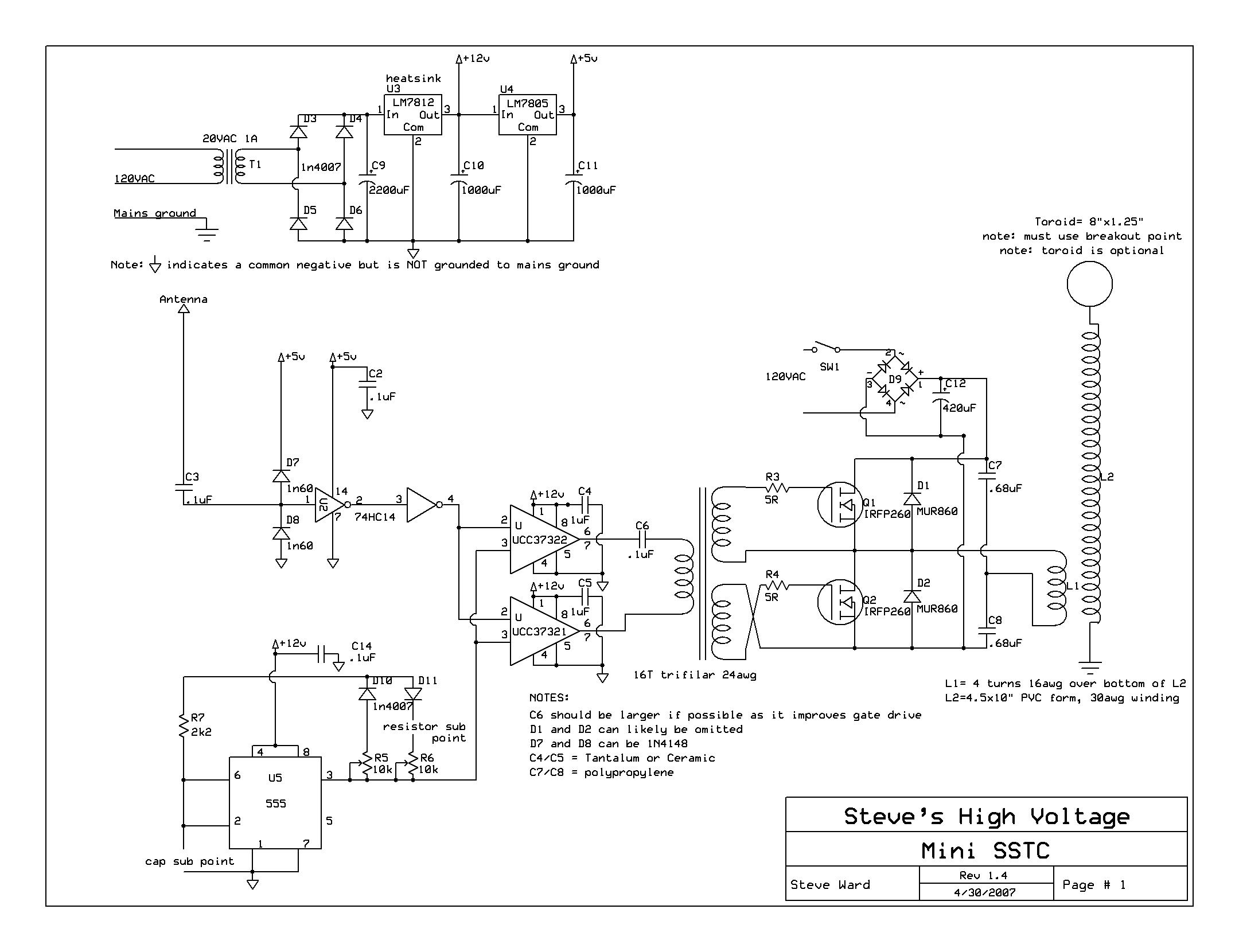
Ok. Now I use half-dridge from this schema (2x IRFP260): miniSSTC
Registered Member #46007
Joined: Wed Apr 30 2014, 08:02PM
Location: Walsall, UK
Posts: 36
Vitalii wrote ...
[ Blue - half bridge output.
>>>2. how many volts it wait on FB-CT (overcurrent protection)? >About 1A is fine. Feedback doesn't provide overcurrent, the OCD feedback does. If you expect 1000A, a 1000:1 current transformer will be fine.
What's the purpose of FB-CT??
Ok. Now I use half-dridge from this schema (2x IRFP260): miniSSTC
How should I wind my FB and OCD transformers?
Hi there, Your FB-CT provides the feedback signal which will drive your coil at the resonant frequency of your primary circuit. http://www.stevehv.4hv.org/drsstc_design.htm This link is a slightly different circuit but the basics of operation are similar certainly in terms of the feedback mechanism and OCD. Here is a good video on winding your CT's : http://youtu.be/HFVR12E2Mek
Also are you building a DRSSTC? That half bridge you linked to is for an SSTC. You may already know but a DRSSTC has a tank capacitor and operates in interrupted mode so only a low duty cycle because the primary tank cap and coil is resonant. An SSTC doesn't have a resonant primary so can operate continuously and has to derive feedback from an antenna or secondary feedback. I wouldn't use MOSFET's for a DRSSTC unless its very low powered (not sure if anyone uses them?) IGBT's are better and TO247 IGBT's are cheap.
This site is powered by e107, which is released under the GNU GPL License. All work on this site, except where otherwise noted, is licensed under a Creative Commons Attribution-ShareAlike 2.5 License. By submitting any information to this site, you agree that anything submitted will be so licensed. Please read our Disclaimer and Policies page for information on your rights and responsibilities regarding this site.


 UD-2.5 - Documentation and help needed


