
UD-2.5 - Documentation and help needed
Vitalii, Mon Sept 08 2014, 01:03AMHi!
I finished build UD 2.5B board two days ago. But have no idea how to start use it. I feel lack of documentations for people like me (I spent only one day to build it but it's my first experience wirh DRSSTC and with UD 2.x drivers).
already have expirience with sstc and tube coils.
I have 2ch oscilloscope, multimeter and regulated power adapter 5-35V and fixed voltage 60 and 120 V (500W) power supply.
Also I have gate from this schema DRSSTC3.
Can you kindly assist me to start as safe as possible (don't damage components of UD 2.5) and give advice (or maybe there's a checklist) how to check that UD 2.5 assembled fine?
And. Really. How to connect all this stuff together?
I have no idea how and where all ports on UD 2.5 should be connected?
Re: UD-2.5 - Documentation and help needed
Cade Brinkley, Mon Sept 08 2014, 01:47AM
So, here's a response from a brand new drsstc-er:
I am sure that there are more experienced out there, but here's my experience as a newbie with the UD 2.5b.
My test setup is a function generator (sine) set to my resonate frequency going into the feedback leads and my scope on the GDT1 leads. I use an 18v transformer connected to a powerstrip for easy on/off.
You could probably use a 555 circuit in place of a function generator if need be.
I flip on the power, then the interrupter, then the simulated feedback. When I first flip it on, the overcurrent and power lights both come on, then when the interrupter is flipped on, the signal light comes on and the overcurrent goes off.
I check to make sure that there is a square wave coming out and that the interrupter is limiting those pulses well.
I have gotten sparks from my system using a board that passed these tests.
And here's the blunders and learning experiences:
First off, it took me a bit to figure out the phase and sv1 pins, there are jumpers that go across those. Pictures of that configuration can be found on the UD 2.5b 4hv post. Also, if you short the gdt leads with an oscilloscope probe, the 24v reg will fly across the room.
I hope I've explained this well, hopefully you can learn from my mistakes and save some component cost:)
Anyone who's more experienced than me (most of you) feel free to correct anything if I'm wrong, I'll learn too:)
Re: UD-2.5 - Documentation and help needed
Vitalii, Mon Sept 08 2014, 11:45AM
You could probably use a 555 circuit in place of a function generator if need be.
>> already made interrupter with 3 ne555 elements. so I can use it as OSD
ok. so as I understand i should:
1. connect square wave henerator running on smth like 700kHz (like my tesla coil) to OCD-CT
2. connect 1ch of oscilloscope to GDT1 and 2ch of oscilloscope to GDT2 (should I connect outputs to GDT on this step?)
3. connect interrupter: - here's a problem because I installed only RX2 (IFD50 optic input) but I have no optical cable and optical TX on my interrupter (which model I should install?). How can I connect interrupter with wires?
4. connect power.
5. the overcurrent and power lights both come on, then when the interrupter is flipped on, the signal light comes on and the overcurrent goes off
What should I see on oscilloscope?
here's a list of additional questions:
1. how shuld I set SV jumper (I didn't install L1)?
2. how many volts it wait on FB-CT (overcurrent protection)?
3. how many volts it wait on OCD-CT?
4. in wich position should I set PHASE jumpers (I use half bridge from Steve's DRSSTC-3)
5. how should I wire GDT? Do I need only GDT1 output? (btw, what is the purpose of GDT2 output? usually people connect one driver output to GDT and 4 output windings from GDT go to the full bridge)
6. what should I see on oscilloscope?
7. Can I use half dridge from Steve's DRSSTC-3 for this setup?
Can I draw document or schema (or maybe it exists somewhere) that explains how to wire UD driver with other Tesla hardware?
I know electronics well, but it's my first DRSSTC and I may make mistake in basic things. thanks for help!!!
Re: UD-2.5 - Documentation and help needed
Vitalii, Wed Sept 10 2014, 02:32PM
It's alive!!!


Fidback triggered with functional generator.
Interrupter triggered with marker lamp (planed to use fiber channel in future, but RF-receiver work with any red light, ha-ha).
So it works!
Most of questions from my previous post now solved.
except one:
Can I use a halfbridge from DRSSTC3????
Vitalii, Wed Sept 10 2014, 02:32PM
It's alive!!!
Fidback triggered with functional generator.
Interrupter triggered with marker lamp (planed to use fiber channel in future, but RF-receiver work with any red light, ha-ha).
So it works!
Most of questions from my previous post now solved.
except one:
Can I use a halfbridge from DRSSTC3????
Re: UD-2.5 - Documentation and help needed
Steve Conner, Wed Sept 10 2014, 03:06PM
You can use the UD with any sort of bridge, full or half.
Steve Conner, Wed Sept 10 2014, 03:06PM
You can use the UD with any sort of bridge, full or half.
Re: UD-2.5 - Documentation and help needed
Vitalii, Mon Sept 15 2014, 02:30PM
Ok. I build transformers for OCD-CT and FB-CT.
How many volts shoud they receive in normal mode (ad how many volts trigger the protection??)
Vitalii, Mon Sept 15 2014, 02:30PM
Ok. I build transformers for OCD-CT and FB-CT.
How many volts shoud they receive in normal mode (ad how many volts trigger the protection??)
Re: UD-2.5 - Documentation and help needed
loneoceans, Mon Sept 15 2014, 04:50PM
>here's a list of additional questions:
>1. how shuld I set SV jumper (I didn't install L1)?
With no L1 installed, jumper pins 1 and 2 (top two).
>2. how many volts it wait on FB-CT (overcurrent protection)?
About 1A is fine. Feedback doesn't provide overcurrent, the OCD feedback does. If you expect 1000A, a 1000:1 current transformer will be fine.
>3. how many volts it wait on OCD-CT?
People usually make another transformer same as the FB-CT for OCD.
>4. in wich position should I set PHASE jumpers (I use half bridge from Steve's DRSSTC-3)
If your coil doesn't oscillate, switch the phase.
>5. how should I wire GDT? Do I need only GDT1 output? (btw, what is the purpose of GDT2 output? usually people connect one driver output to GDT and 4 output windings from GDT go to the full bridge)
You only need one GDT output. The purpose of the second output is for increased power capability (can be wired in parallel), or driving a second half of the bridge in a full bridge. You can ignore the other output if you're not using it.
>6. what should I see on oscilloscope?
Depends on what you measure.
>7. Can I use half dridge from Steve's DRSSTC-3 for this setup?
Yes you can use any sort of bridge, half, full, double, etc.
>Can I draw document or schema (or maybe it exists somewhere) that explains how to wire UD driver with other Tesla hardware?
>I know electronics well, but it's my first DRSSTC and I may make mistake in basic things. thanks for help!!!
I'm working on documentation for the UD so I'll be sure to post it when I'm done. However, I urge you to study the schematic a bit more. Building a DRSSTC is not a trivial task, and if you're using a UD2 you should be familiar enough with the basic workings of solid state coils to debug it yourself effectively. A good way to start is to build a normal SSTC first with basic antenna or secondary feedback. Good luck!
Re: UD-2.5 - Documentation and help needed
Vitalii, Wed Sept 17 2014, 09:07AM

Yelow - UD2.5 output
Blue - half bridge output.
>>>2. how many volts it wait on FB-CT (overcurrent protection)?
>About 1A is fine. Feedback doesn't provide overcurrent, the OCD feedback does. If you expect 1000A, a 1000:1 current transformer will be fine.
What's the purpose of FB-CT??
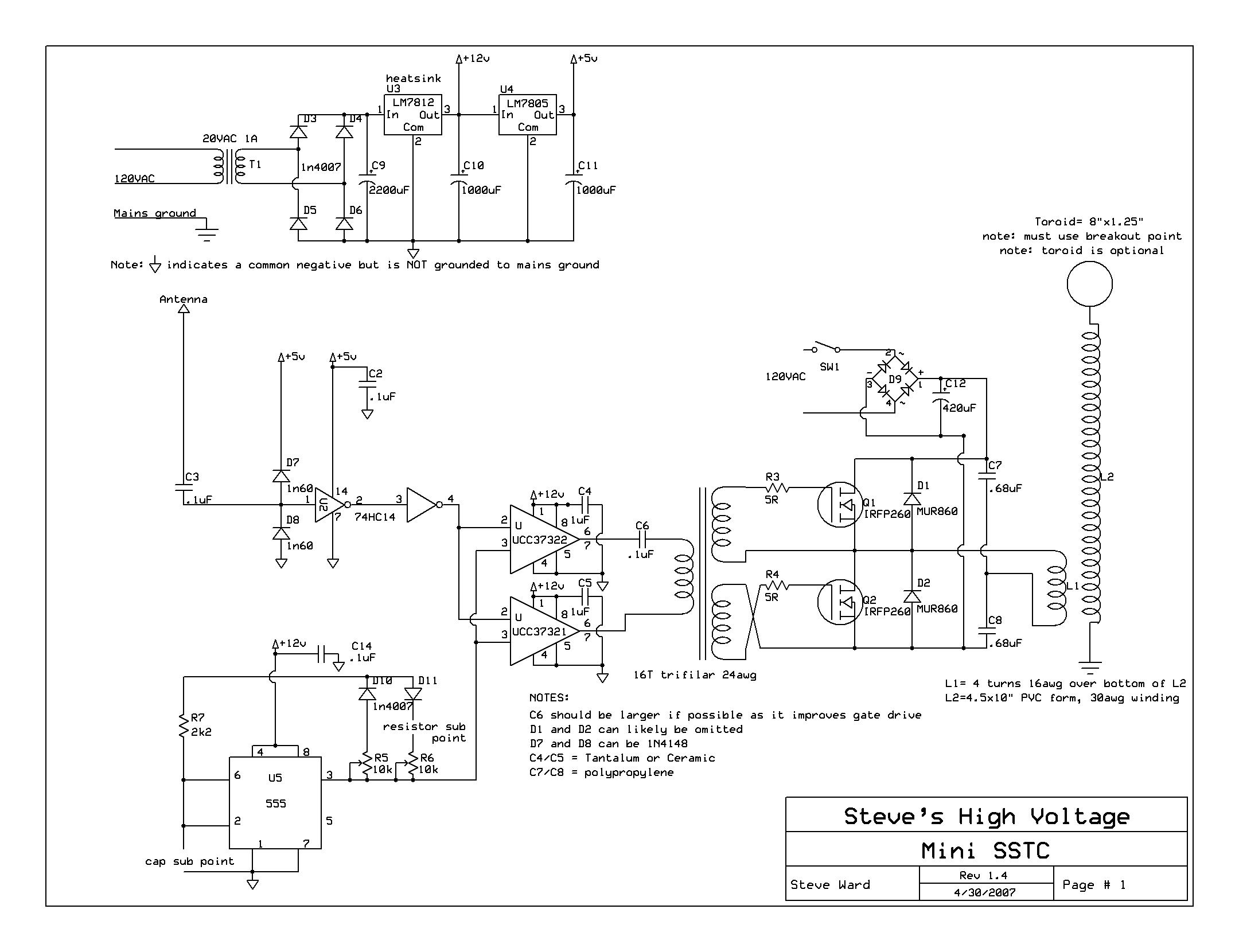
Ok. Now I use half-dridge from this schema (2x IRFP260):
miniSSTC
How should I wind my FB and OCD transformers?
Vitalii, Wed Sept 17 2014, 09:07AM
Yelow - UD2.5 output
Blue - half bridge output.
>>>2. how many volts it wait on FB-CT (overcurrent protection)?
>About 1A is fine. Feedback doesn't provide overcurrent, the OCD feedback does. If you expect 1000A, a 1000:1 current transformer will be fine.
What's the purpose of FB-CT??
Ok. Now I use half-dridge from this schema (2x IRFP260):
miniSSTC
How should I wind my FB and OCD transformers?
Re: UD-2.5 - Documentation and help needed
chris_inkubate, Wed Sept 17 2014, 06:42PM
Hi there,
Your FB-CT provides the feedback signal which will drive your coil at the resonant frequency of your primary circuit. http://www.stevehv.4hv.org/drsstc_design.htm This link is a slightly different circuit but the basics of operation are similar certainly in terms of the feedback mechanism and OCD. Here is a good video on winding your CT's : http://youtu.be/HFVR12E2Mek
Also are you building a DRSSTC? That half bridge you linked to is for an SSTC. You may already know but a DRSSTC has a tank capacitor and operates in interrupted mode so only a low duty cycle because the primary tank cap and coil is resonant. An SSTC doesn't have a resonant primary so can operate continuously and has to derive feedback from an antenna or secondary feedback. I wouldn't use MOSFET's for a DRSSTC unless its very low powered (not sure if anyone uses them?) IGBT's are better and TO247 IGBT's are cheap.
Chris
chris_inkubate, Wed Sept 17 2014, 06:42PM
Vitalii wrote ...
[
Blue - half bridge output.
>>>2. how many volts it wait on FB-CT (overcurrent protection)?
>About 1A is fine. Feedback doesn't provide overcurrent, the OCD feedback does. If you expect 1000A, a 1000:1 current transformer will be fine.
What's the purpose of FB-CT??
Ok. Now I use half-dridge from this schema (2x IRFP260):
miniSSTC
How should I wind my FB and OCD transformers?
Hi there,
Your FB-CT provides the feedback signal which will drive your coil at the resonant frequency of your primary circuit. http://www.stevehv.4hv.org/drsstc_design.htm This link is a slightly different circuit but the basics of operation are similar certainly in terms of the feedback mechanism and OCD. Here is a good video on winding your CT's : http://youtu.be/HFVR12E2Mek
Also are you building a DRSSTC? That half bridge you linked to is for an SSTC. You may already know but a DRSSTC has a tank capacitor and operates in interrupted mode so only a low duty cycle because the primary tank cap and coil is resonant. An SSTC doesn't have a resonant primary so can operate continuously and has to derive feedback from an antenna or secondary feedback. I wouldn't use MOSFET's for a DRSSTC unless its very low powered (not sure if anyone uses them?) IGBT's are better and TO247 IGBT's are cheap.
Chris
Re: UD-2.5 - Documentation and help needed
Vitalii, Sun Sept 21 2014, 08:55PM
Hi!
I made 1:1000 transformer exactly as it was described on
But my cerquit doesn't oscilate with it. I tryed to change phase. but no.
In the same cerquit with 1:48 transformer it works fine.
Can it be caused by low power voltage (I make all tests with 16V power supply on my mosfet half-bridge)?
Re: UD-2.5 - Documentation and help needed
Thomas W, Sun Sept 21 2014, 10:07PM
Its not about how many volts are there, its about the current flowing through,
if you have 1A flowing through the transformer at 1:48, you will have a current of around 21mA flowing through a 1 Ohm resistor, however at 1:1000 you will have 1mA flowing through a 1 Ohm resistor at 1A through the primary.
as you can imagine, 0.021V is easier to read then 0.001V
My math may not be correct ( i haven't looked into this stuff all that much)
but its still over a whole magnatude difference in reduction.
if you have a higher current flowing through the 1:1000 current transformer, you will likely get it to oscillate.
Re: UD-2.5 - Documentation and help needed
Vitalii, Mon Sept 22 2014, 09:56AM
thanks!
Got it.
then I was wrong because in my opinion FB-CT input is triggred by voltage and 1:1000 transformer increases it.
But your point is that FB-CT input is triggered by current (and it's obsolutly right). So it devides the current I=Iprimary/K (where K=1/1000).
Thanks for addvice.
But how about OCD?
How should I calibrate it?
Re: UD-2.5 - Documentation and help needed
Vitalii, Mon Sept 22 2014, 09:57AM
also I have 4x 50B60 IGBTs. Which schema should I build??
Vitalii, Mon Sept 22 2014, 09:57AM
also I have 4x 50B60 IGBTs. Which schema should I build??
Re: UD-2.5 - Documentation and help needed
Vitalii, Fri Jan 09 2015, 03:17PM
ok.
So the problem with my tesla was that I never managed system in zero voltage detection mode. The delay was too big and produced a lot of heating and noise on IGBT's gates.
Now it's fine.
Unfortunately, nobody answered and showed me my mistake so I spent a lot of time for debugging.
Re: UD-2.5 - Documentation and help needed
TeslaRay, Tue Jan 13 2015, 03:06PM
good morning - I have a few questions regarding UD 2.5 also.
a. for driving large igbt bricks in full bridge, should I use a single output or parallel two outputs on a single gate drive transformer, or use two outputs and two smaller gate drive transformers.
b. is there a rule of thumb regarding how to select the proper inductor range for phase tuning per the size or frequency of the tesla coil?
Re: UD-2.5 - Documentation and help needed
Vitalii, Tue Jan 13 2015, 06:29PM
One more question is about FB and OCD input.
I'm running H-bridge of 50B60. 2 transformers (one for OCD and one for FB) are 1\33 - 1\33.
A. What's the normal voltage on R1 for triggering feedback?
B. How much volts should I set on OCD resistor to prevent burning?
Vitalii, Tue Jan 13 2015, 06:29PM
One more question is about FB and OCD input.
I'm running H-bridge of 50B60. 2 transformers (one for OCD and one for FB) are 1\33 - 1\33.
A. What's the normal voltage on R1 for triggering feedback?
B. How much volts should I set on OCD resistor to prevent burning?
Re: UD-2.5 - Documentation and help needed
loneoceans, Tue Jan 13 2015, 06:32PM
Hey guys I originally wrote up the UD2 page aimed at answering questions like these - Reading through there first would likely answer many of your questions.
loneoceans, Tue Jan 13 2015, 06:32PM
Hey guys I originally wrote up the UD2 page aimed at answering questions like these -
Reading through there first would likely answer many of your questions.Print this page