If you need assistance, please send an email to forum at 4hv dot org. To ensure your email is not marked as spam, please include the phrase "4hv help" in the subject line. You can also find assistance via IRC, at irc.shadowworld.net, room #hvcomm.
Support 4hv.org!
Donate:
4hv.org is hosted on a dedicated server. Unfortunately, this server costs and we rely on the help of site members to keep 4hv.org running. Please consider donating. We will place your name on the thanks list and you'll be helping to keep 4hv.org alive and free for everyone. Members whose names appear in red bold have donated recently. Green bold denotes those who have recently donated to keep the server carbon neutral.
Special Thanks To:
Aaron Holmes
Aaron Wheeler
Adam Horden
Alan Scrimgeour
Andre
Andrew Haynes
Anonymous000
asabase
Austin Weil
barney
Barry
Bert Hickman
Bill Kukowski
Blitzorn
Brandon Paradelas
Bruce Bowling
BubeeMike
Byong Park
Cesiumsponge
Chris F.
Chris Hooper
Corey Worthington
Derek Woodroffe
Dalus
Dan Strother
Daniel Davis
Daniel Uhrenholt
datasheetarchive
Dave Billington
Dave Marshall
David F.
Dennis Rogers
drelectrix
Dr. John Gudenas
Dr. Spark
E.TexasTesla
eastvoltresearch
Eirik Taylor
Erik Dyakov
Erlend^SE
Finn Hammer
Firebug24k
GalliumMan
Gary Peterson
George Slade
GhostNull
Gordon Mcknight
Graham Armitage
Grant
GreySoul
Henry H
IamSmooth
In memory of Leo Powning
Jacob Cash
James Howells
James Pawson
Jeff Greenfield
Jeff Thomas
Jesse Frost
Jim Mitchell
jlr134
Joe Mastroianni
John Forcina
John Oberg
John Willcutt
Jon Newcomb
klugesmith
Leslie Wright
Lutz Hoffman
Mads Barnkob
Martin King
Mats Karlsson
Matt Gibson
Matthew Guidry
mbd
Michael D'Angelo
Mikkel
mileswaldron
mister_rf
Neil Foster
Nick de Smith
Nick Soroka
nicklenorp
Nik
Norman Stanley
Patrick Coleman
Paul Brodie
Paul Jordan
Paul Montgomery
Ped
Peter Krogen
Peter Terren
PhilGood
Richard Feldman
Robert Bush
Royce Bailey
Scott Fusare
Scott Newman
smiffy
Stella
Steven Busic
Steve Conner
Steve Jones
Steve Ward
Sulaiman
Thomas Coyle
Thomas A. Wallace
Thomas W
Timo
Torch
Ulf Jonsson
vasil
Vaxian
vladi mazzilli
wastehl
Weston
William Kim
William N.
William Stehl
Wesley Venis
The aforementioned have contributed financially to the continuing triumph of 4hv.org. They are deserving of my most heartfelt thanks.
Registered Member #543
Joined: Tue Feb 20 2007, 04:26PM
Location: UK
Posts: 4992
Life Below 5 keV
Under continuous development
This thread is about very low energy ionising radiation produced by sources supplied with less than 5 kV - the cut-off point for ionising radiation regulation in the UK and EC.
Nothing described or discussed here is a "radiation generator" as defined by The Ionising Radiations Regulations 1999 and European Council Directive 92/3/Euratom as "electrical equipment emitting ionising radiation and containing components operating at a potential difference of more than 5kV".
As might be expected, these very soft rays of less than 4.999 keV do not travel very far through air at atmospheric pressure, as the following three graphs show.
About 60% will manage to cross a gap of 10cm.
Only about 9% will make it across 50cm
And only 0.008% of those that started their journey will not have been absorbed after passing through 100 cm of air.
We would still be able to detect them with good equipment, but only a little further away and they will have vanished without trace.
Power Supplies
A. A Bertan Model 313A 0 - 3 kV 10mA regulated PSU. Any voltage from 0 - 3 kV may be dialled up in increments of 1V. The polarity of the output may be changed by means of screwdriver set switch on top of the unit, and the corresponding NEG and POS indicators will light up accordingly. The picture shows the PSU set for an output of 2999 V. As a safety feature, the ON/OFF toggle switch must first be pulled out towards the user before the switch can be thrown. The output is delivered via an SHV connector (a type of coaxial socket very similar to BNC, but with a 5 kV rating)) on the back.
B.To fill in the gap between the Bertan's 3 kV, and our 4.999 kV maximum, I have built a simple PSU able to supply up to 4.99 kV positive or negative to allow use of electron-impact photon sources of both the grounded anode and the grounded cathode type.
Here is the circuit of the 4.999 kV dual rail PSU I made from bits and pieces I found in a cupboard under the stairs:
I used an old Tunewell 5 kV-0-5kV 30 mA neon sign transformer as the basis of my design, because I happened to have one, but I'm sure that there are many better ways of producing a dual rail HV supply than the simple circuit I have built here.
I used a rotary cutter to enlarge an existing hole in the case to install the blue Neutrik locking mains power connector. The other case hole was too large for a standard DPST mains toggle switch, so I had to add an aluminium blanking plate to accommodate it.
Swarf and filings that fell on the surface of the bitumen potting compound stuck fast - grrrrr! - and was tedious to remove.
For point-to-point I used a mixture of 25 kV EHT cable, and silicone rubber sleeving reinforced by adhesive heat shrink at places of likely electrical stress.
The fat red and blue output cables are rated at >30 kV.
As you see, a typical bodge, but it worked the first time I threw the switch, always a moment of trepidation!
The 200nF capacitors in the diagram are made from two 0.1 μF 6 kV Russian units in parallel. I should have liked to have more capacitance than this, but that's all I had to hand that would fit in the case. I can always add more capacitance externally if ripple becomes an issue in some future experiment.
The diodes are HVR-1X-3 12 kV microwave oven types, though diodes with a much lower current rating could have been used.
This is by no means a regulated supply (! ) so one needs to start the variac at the low end, and gradually wind it up until the desired voltage is reached under load.
I found that this simple apparatus will produce a dual rail 4.999 kV output at 4 mA - ~20W per rail - without problem, and will hold on the voltage set so long as the load is constant. At 10 mA from a single rail (two Russian 910k 10W HV resistors in parallel), the voltage falls to 4.5 kV as the transformer's magnetic shunts kick in, a nice turn of mental arithmetic.
In any event, 20W is more than enough power for the experiments I'll be attempting and describing in this minimalist project.
Low Tension Filament Supplies
Thermionic devices require an LT supply for filaments and heaters. In the low energy photon sources I shall be using in these experiments, voltages from 1 - 3V will be required at currents up to 3.5 A. Clearly, a filament supply for use with a grounded anode tube, where the cathode is held at high negative voltage, must be floating with respect to Earth, and capable of withstanding the full HV- supply. The easiest way to do this well is to use high capacity NiMH and compact lead-acid cells. Here are the rechargeable 1.2V 9 AH NiMH and 2V 8 AH Cyclon lead-acid cells which I use as a floating filament supply. They provide the needed power for an hour or so without much fall in output - far longer than is required in any of my experiments.
Registered Member #543
Joined: Tue Feb 20 2007, 04:26PM
Location: UK
Posts: 4992
Ash Small wrote ...
Very interesting, I'm looking forward to future posts in this thread.
Will this require shielding, or just a metre of air?
Shielding and great care most certainly is required in the ultra soft, if adverse events are to be avoided, Mr Ash, and I will deal with it in detail later on.
In the meantime, I'll note that 1 mm aluminium sheet is sufficient to reduce a 4.99 keV photon beam to undetectable limits - i.e. by the order of 10E-22, as the graph below illustrates:
So no back-breaking rolls of toxic lead sheet to be humped about, flattened with wooden rolling pins, and formed with rubber mallets!
Registered Member #543
Joined: Tue Feb 20 2007, 04:26PM
Location: UK
Posts: 4992
Voltage Measurement
I've been using this 1000:1 HV prove for general setting up, but will get round to making a dedicated 5 kV voltmeter that I can clip onto a circuit under test more easily.
This old workhorse claims to be good to 40 kV - but rather you than me!
Registered Member #543
Joined: Tue Feb 20 2007, 04:26PM
Location: UK
Posts: 4992
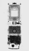
Test Rig 1 with front and side shielding down
Nothing illustrated or discussed here is a "radiation generator" as defined by The Ionising Radiations Regulations 1999 and European Council Directive 92/3/Euratom as "electrical equipment emitting ionising radiation and containing components operating at a potential difference of more than 5kV".
Low Energy Test
PSU: Bertan 313A Detector: Mini Instruments Mini-Monitor GM Meter Type 510 with Philips ZP1430 mica end-window GM tube. Distance: 1 cm
I can not say whether 2.25 keV represents the lowest energy photons that can escape through the Be window, or the lowest energy that once having transited the Be exit window and the air gap, can then penetrate the mica window of the GM tube, and initiate a Townsend event. i.e. I can't tell if the tube is emitting photons below 2.25 keV that are not being detected because of the limitations of the GM tube.
Registered Member #543
Joined: Tue Feb 20 2007, 04:26PM
Location: UK
Posts: 4992
BSV-7-Fe Low Energy Test
The Svetlana BSV-7-Fe is a water-cooled triode electron-impact iron anode photon source, where the electron beam is gated by a grid to facilitate anode current control without changing the filament current. It has a maximum 25W input. Photon output via diametrically opposed beryllium windows is in the form of a line 2 mm * 0,075 mm for use in diffraction analysis. The iron anode is intended for use in diffraction studies where Fe fluorescence noise could be a problem. This particular example was manufactured in March 1980.
For this test, I have provided water cooling for the anode block by means of an aquarium pump in a tub of de-ionised water. The tubing is Samco silicone rubber vacuum hose.
I have also blanked off the Be window on the reverse side of the tube with a strip of self-adhesive lead tape, effectively reducing its output below 4.999 keV to zero. (The windows on this particular tube are indented slightly below the cylindrical surface of the anode block, so there is no adhesion to the fragile window itself.)
The test result for this tube is similar to the result for BSM-1-Ni, with first indications of emission occurring at around 2.3 kV, and then taking off steeply as Va is increased. Changing from a nickel to an iron anode has not made any difference I can measure.
The only way I can find out if emission is occurring below ~2.3 kV is by constructing a detector with improved low energy response, which I shall now get on with...
I found I had a tupperware box with some CMOS op amps in it - a small tube of LMC662 and two longer tubes of TLC27L2 - so I'll give the circuit a go with what I have to hand.
The TLC27L2 claims to have 2 kV ESD protection, so I'll try bodging it together with these first, as per my circuit diagram.
Registered Member #1134
Joined: Tue Nov 20 2007, 04:39PM
Location: Bonnie Scotland
Posts: 351
I was thinking about this last night a little, and started looking at using smoke detector IC's as a possible front end.
On the attached MC145017.pdf, the frequency on OSC pin 12 seems to vary depending on the level of ionisation in the chamber.
Maybe this could be put to use, or maybe it is wholly unsuitable!
There is another, that looks a little more useful for an application like this (22162A-1.pdf), a RE46C112E8F which seems a little more useful, as it is minus the horn and LED driver sections of the MC145017, and has a nice analogue output.
The RE46C112E8F is available from Farnell, and carries with it the flea sized price tag of 59p including VAT.
Registered Member #543
Joined: Tue Feb 20 2007, 04:26PM
Location: UK
Posts: 4992
It's certainly an idea, Les, and I did have some thoughts about the ionisation chamber part of the annoying toast detector on the ceiling, but I'm already stuck into the first version of the trans impedance amplifier with parts I already have to hand.
Having ditched the americium source, it might be possible to take the frequency on OSC pin 12 of MC145017, and use it to operate a meter via a FtV converter, or perhaps using a 555 timer in one of those RPM type circuits, or in one of those switchable RC time constant rate meter circuits you see in old GM counters.
As for the chamber itself, I've been looking through the archaic literature of Grenz rays, and have got a much better idea of the best (or better!) geometry for high efficiency in the ultra soft than I had before.
As you'll see from this graph here, I'd got the wrong end of the stick with the dimensions - but not the need for large corrections - in the measurement of the Grenz rays:
By the lights of this graph, I have only to make my chamber a bit longer to have 100% efficiency below 4.999 keV. However, I've found some suggestion that strong ionisation at the entry to the chamber may block softer rays from going further, which can be compensated for by introducing a reverse taper.
As I'm having to make everything up as I go along, I'm sure I'll have to change a great deal to get it all working, but one has to start somewhere!
Registered Member #3414
Joined: Sun Nov 14 2010, 05:05PM
Location: UK
Posts: 4245
@ Les and P.M.: I'm sure I'm not the only one here who'd be interested to know how to convert a 'ceiling mounted burnt toast' alpha particle detector into a weak gamma ray/X-ray detector.
Will this still require the photo-multiplier, etc. that conventional detectors use?
This site is powered by e107, which is released under the GNU GPL License. All work on this site, except where otherwise noted, is licensed under a Creative Commons Attribution-ShareAlike 2.5 License. By submitting any information to this site, you agree that anything submitted will be so licensed. Please read our Disclaimer and Policies page for information on your rights and responsibilities regarding this site.


 Life Below 5 keV