Life Below 5 keV
Proud Mary, Fri Jun 01 2012, 06:25PMLife Below 5 keV
Under continuous development
This thread is about very low energy ionising radiation produced by sources supplied with less than 5 kV - the cut-off point for ionising radiation regulation in the UK and EC.
Nothing described or discussed here is a "radiation generator" as defined by The Ionising Radiations Regulations 1999 and European Council Directive 92/3/Euratom as "electrical equipment emitting ionising radiation and containing components operating at a potential difference of more than 5kV".
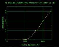
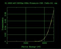
As might be expected, these very soft rays of less than 4.999 keV do not travel very far through air at atmospheric pressure, as the following three graphs show.
About 60% will manage to cross a gap of 10cm.
Only about 9% will make it across 50cm
And only 0.008% of those that started their journey will not have been absorbed after passing through 100 cm of air.
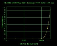
We would still be able to detect them with good equipment, but only a little further away and they will have vanished without trace.
Power Supplies
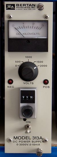
A. A Bertan Model 313A 0 - 3 kV 10mA regulated PSU. Any voltage from 0 - 3 kV may be dialled up in increments of 1V. The polarity of the output may be changed by means of screwdriver set switch on top of the unit, and the corresponding NEG and POS indicators will light up accordingly. The picture shows the PSU set for an output of 2999 V. As a safety feature, the ON/OFF toggle switch must first be pulled out towards the user before the switch can be thrown. The output is delivered via an SHV connector (a type of coaxial socket very similar to BNC, but with a 5 kV rating)) on the back.
B.To fill in the gap between the Bertan's 3 kV, and our 4.999 kV maximum, I have built a simple PSU able to supply up to 4.99 kV positive or negative to allow use of electron-impact photon sources of both the grounded anode and the grounded cathode type.
Here is the circuit of the 4.999 kV dual rail PSU I made from bits and pieces I found in a cupboard under the stairs:

I used an old Tunewell 5 kV-0-5kV 30 mA neon sign transformer as the basis of my design, because I happened to have one, but I'm sure that there are many better ways of producing a dual rail HV supply than the simple circuit I have built here.
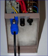
I used a rotary cutter to enlarge an existing hole in the case to install the blue Neutrik locking mains power connector. The other case hole was too large for a standard DPST mains toggle switch, so I had to add an aluminium blanking plate to accommodate it.
Swarf and filings that fell on the surface of the bitumen potting compound stuck fast - grrrrr! - and was tedious to remove.
For point-to-point I used a mixture of 25 kV EHT cable, and silicone rubber sleeving reinforced by adhesive heat shrink at places of likely electrical stress.
The fat red and blue output cables are rated at >30 kV.
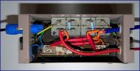
As you see, a typical bodge, but it worked the first time I threw the switch, always a moment of trepidation!

The 200nF capacitors in the diagram are made from two 0.1 μF 6 kV Russian units in parallel. I should have liked to have more capacitance than this, but that's all I had to hand that would fit in the case. I can always add more capacitance externally if ripple becomes an issue in some future experiment.
The 68 MΩ bleeder resistors are Vishay HV VR68 types. They ensure that no disagreeable charge lingers on the capacitors for very long after the apparatus has been switched off.
The diodes are HVR-1X-3 12 kV microwave oven types, though diodes with a much lower current rating could have been used.
This is by no means a regulated supply (!
 ) so one needs to start the variac at the low end, and gradually wind it up until the desired voltage is reached under load.
I found that this simple apparatus will produce a dual rail 4.999 kV output at 4 mA - ~20W per rail - without problem, and will hold on the voltage set so long as the load is constant. At 10 mA from a single rail (two Russian 910k 10W HV resistors in parallel), the voltage falls to 4.5 kV as the transformer's magnetic shunts kick in, a nice turn of mental arithmetic.
In any event, 20W is more than enough power for the experiments I'll be attempting and describing in this minimalist project.
Low Tension Filament Supplies
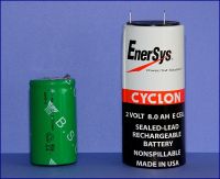
Thermionic devices require an LT supply for filaments and heaters. In the low energy photon sources I shall be using in these experiments, voltages from 1 - 3V will be required at currents up to 3.5 A. Clearly, a filament supply for use with a grounded anode tube, where the cathode is held at high negative voltage, must be floating with respect to Earth, and capable of withstanding the full HV- supply. The easiest way to do this well is to use high capacity NiMH and compact lead-acid cells. Here are the rechargeable 1.2V 9 AH NiMH and 2V 8 AH Cyclon lead-acid cells which I use as a floating filament supply. They provide the needed power for an hour or so without much fall in output - far longer than is required in any of my experiments.
Re: Life Below 5 keV
Ash Small, Fri Jun 01 2012, 07:49PM
Very interesting, I'm looking forward to future posts in this thread.
Will this require shielding, or just a metre of air?
Ash Small, Fri Jun 01 2012, 07:49PM
Very interesting, I'm looking forward to future posts in this thread.
Will this require shielding, or just a metre of air?
Re: Life Below 5 keV
Proud Mary, Sat Jun 02 2012, 10:44AM
Shielding and great care most certainly is required in the ultra soft, if adverse events are to be avoided, Mr Ash, and I will deal with it in detail later on.
In the meantime, I'll note that 1 mm aluminium sheet is sufficient to reduce a 4.99 keV photon beam to undetectable limits - i.e. by the order of 10E-22, as the graph below illustrates:
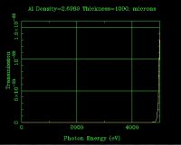
So no back-breaking rolls of toxic lead sheet to be humped about, flattened with wooden rolling pins, and formed with rubber mallets!
Proud Mary, Sat Jun 02 2012, 10:44AM
Ash Small wrote ...
Very interesting, I'm looking forward to future posts in this thread.
Will this require shielding, or just a metre of air?
Very interesting, I'm looking forward to future posts in this thread.
Will this require shielding, or just a metre of air?
Shielding and great care most certainly is required in the ultra soft, if adverse events are to be avoided, Mr Ash, and I will deal with it in detail later on.
In the meantime, I'll note that 1 mm aluminium sheet is sufficient to reduce a 4.99 keV photon beam to undetectable limits - i.e. by the order of 10E-22, as the graph below illustrates:

So no back-breaking rolls of toxic lead sheet to be humped about, flattened with wooden rolling pins, and formed with rubber mallets!
Re: Life Below 5 keV
Proud Mary, Sun Jun 03 2012, 01:38PM
Voltage Measurement
I've been using this 1000:1 HV prove for general setting up, but will get round to making a dedicated 5 kV voltmeter that I can clip onto a circuit under test more easily.
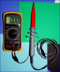
This old workhorse claims to be good to 40 kV - but rather you than me!
Proud Mary, Sun Jun 03 2012, 01:38PM
Voltage Measurement
I've been using this 1000:1 HV prove for general setting up, but will get round to making a dedicated 5 kV voltmeter that I can clip onto a circuit under test more easily.

This old workhorse claims to be good to 40 kV - but rather you than me!

Re: Life Below 5 keV
Proud Mary, Thu Jun 07 2012, 06:49PM
Test Rig 1
with front and side shielding down
Nothing illustrated or discussed here is a "radiation generator" as defined by The Ionising Radiations Regulations 1999 and European Council Directive 92/3/Euratom as "electrical equipment emitting ionising radiation and containing components operating at a potential difference of more than 5kV".
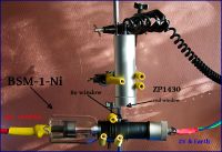
Low Energy Test
PSU: Bertan 313A
Detector: Mini Instruments Mini-Monitor GM Meter Type 510 with Philips ZP1430 mica end-window GM tube.
Distance: 1 cm
2.25 kV - started to rise above background, then
2.5 kV - 30 cps
2.6 kV - 70 cps
2.7 kV - 160 cps
2.8 kV - 350 cps
2.9 kV - 700 cps
3 kv - 1250 cps
I can not say whether 2.25 keV represents the lowest energy photons that can escape through the Be window, or the lowest energy that once having transited the Be exit window and the air gap, can then penetrate the mica window of the GM tube, and initiate a Townsend event.
i.e. I can't tell if the tube is emitting photons below 2.25 keV that are not being detected because of the limitations of the GM tube.
Perhaps a test with a different tube...
Proud Mary, Thu Jun 07 2012, 06:49PM
Test Rig 1
with front and side shielding down
Nothing illustrated or discussed here is a "radiation generator" as defined by The Ionising Radiations Regulations 1999 and European Council Directive 92/3/Euratom as "electrical equipment emitting ionising radiation and containing components operating at a potential difference of more than 5kV".

Low Energy Test
PSU: Bertan 313A
Detector: Mini Instruments Mini-Monitor GM Meter Type 510 with Philips ZP1430 mica end-window GM tube.
Distance: 1 cm
2.25 kV - started to rise above background, then
2.5 kV - 30 cps
2.6 kV - 70 cps
2.7 kV - 160 cps
2.8 kV - 350 cps
2.9 kV - 700 cps
3 kv - 1250 cps
I can not say whether 2.25 keV represents the lowest energy photons that can escape through the Be window, or the lowest energy that once having transited the Be exit window and the air gap, can then penetrate the mica window of the GM tube, and initiate a Townsend event.
i.e. I can't tell if the tube is emitting photons below 2.25 keV that are not being detected because of the limitations of the GM tube.
Perhaps a test with a different tube...
Re: Life Below 5 keV
Proud Mary, Fri Jun 08 2012, 06:54PM
BSV-7-Fe Low Energy Test
The Svetlana BSV-7-Fe is a water-cooled triode electron-impact iron anode photon source, where the electron beam is gated by a grid to facilitate anode current control without changing the filament current. It has a maximum 25W input. Photon output via diametrically opposed beryllium windows is in the form of a line 2 mm * 0,075 mm for use in diffraction analysis. The iron anode is intended for use in diffraction studies where Fe fluorescence noise could be a problem. This particular example was manufactured in March 1980.
For this test, I have provided water cooling for the anode block by means of an aquarium pump in a tub of de-ionised water. The tubing is Samco silicone rubber vacuum hose.
I have also blanked off the Be window on the reverse side of the tube with a strip of self-adhesive lead tape, effectively reducing its output below 4.999 keV to zero. (The windows on this particular tube are indented slightly below the cylindrical surface of the anode block, so there is no adhesion to the fragile window itself.)
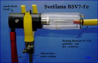
The test result for this tube is similar to the result for BSM-1-Ni, with first indications of emission occurring at around 2.3 kV, and then taking off steeply as Va is increased. Changing from a nickel to an iron anode has not made any difference I can measure.
The only way I can find out if emission is occurring below ~2.3 kV is by constructing a detector with improved low energy response, which I shall now get on with...
Proud Mary, Fri Jun 08 2012, 06:54PM
BSV-7-Fe Low Energy Test
The Svetlana BSV-7-Fe is a water-cooled triode electron-impact iron anode photon source, where the electron beam is gated by a grid to facilitate anode current control without changing the filament current. It has a maximum 25W input. Photon output via diametrically opposed beryllium windows is in the form of a line 2 mm * 0,075 mm for use in diffraction analysis. The iron anode is intended for use in diffraction studies where Fe fluorescence noise could be a problem. This particular example was manufactured in March 1980.
For this test, I have provided water cooling for the anode block by means of an aquarium pump in a tub of de-ionised water. The tubing is Samco silicone rubber vacuum hose.
I have also blanked off the Be window on the reverse side of the tube with a strip of self-adhesive lead tape, effectively reducing its output below 4.999 keV to zero. (The windows on this particular tube are indented slightly below the cylindrical surface of the anode block, so there is no adhesion to the fragile window itself.)

The test result for this tube is similar to the result for BSM-1-Ni, with first indications of emission occurring at around 2.3 kV, and then taking off steeply as Va is increased. Changing from a nickel to an iron anode has not made any difference I can measure.
The only way I can find out if emission is occurring below ~2.3 kV is by constructing a detector with improved low energy response, which I shall now get on with...
Re: Life Below 5 keV
Proud Mary, Sun Jun 10 2012, 02:39PM
After mulling over the different sorts of circuits I could use for the front end of an ionisation chamber detector, I rejected options using preposterously high resistances - 100 GΩ and such - as would make so much noise you wouldn't be able to hear yourself think. This left me with the Trans Impedance Amplifier using a T-network to increase the effective value of the feedback resistance.
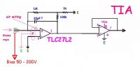
I found I had a tupperware box with some CMOS op amps in it - a small tube of LMC662 and two longer tubes of TLC27L2 - so I'll give the circuit a go with what I have to hand.
The TLC27L2 claims to have 2 kV ESD protection, so I'll try bodging it together with these first, as per my circuit diagram.
To be continued...
Proud Mary, Sun Jun 10 2012, 02:39PM
After mulling over the different sorts of circuits I could use for the front end of an ionisation chamber detector, I rejected options using preposterously high resistances - 100 GΩ and such - as would make so much noise you wouldn't be able to hear yourself think. This left me with the Trans Impedance Amplifier using a T-network to increase the effective value of the feedback resistance.

I found I had a tupperware box with some CMOS op amps in it - a small tube of LMC662 and two longer tubes of TLC27L2 - so I'll give the circuit a go with what I have to hand.
The TLC27L2 claims to have 2 kV ESD protection, so I'll try bodging it together with these first, as per my circuit diagram.
To be continued...
Re: Life Below 5 keV
plazmatron, Sun Jun 10 2012, 05:51PM
I was thinking about this last night a little, and started looking at using smoke detector IC's as a possible front end.
On the attached MC145017.pdf, the frequency on OSC pin 12 seems to vary depending on the level of ionisation in the chamber.
Maybe this could be put to use, or maybe it is wholly unsuitable!
There is another, that looks a little more useful for an application like this (22162A-1.pdf), a RE46C112E8F which seems a little more useful, as it is minus the horn and LED driver sections of the MC145017, and has a nice analogue output.
The RE46C112E8F is available from Farnell, and carries with it the flea sized price tag of 59p including VAT.
Les
]ion_chamber.zip[/file]
Re: Life Below 5 keV
Proud Mary, Sun Jun 10 2012, 08:42PM
It's certainly an idea, Les, and I did have some thoughts about the ionisation chamber part of the annoying toast detector on the ceiling, but I'm already stuck into the first version of the trans impedance amplifier with parts I already have to hand.
Having ditched the americium source, it might be possible to take the frequency on OSC pin 12 of MC145017, and use it to operate a meter via a FtV converter, or perhaps using a 555 timer in one of those RPM type circuits, or in one of those switchable RC time constant rate meter circuits you see in old GM counters.
As for the chamber itself, I've been looking through the archaic literature of Grenz rays, and have got a much better idea of the best (or better!) geometry for high efficiency in the ultra soft than I had before.
As you'll see from this graph here, I'd got the wrong end of the stick with the dimensions - but not the need for large corrections - in the measurement of the Grenz rays:
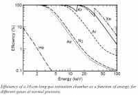
By the lights of this graph, I have only to make my chamber a bit longer to have 100% efficiency below 4.999 keV. However, I've found some suggestion
that strong ionisation at the entry to the chamber may block softer rays from going further, which can be compensated for by introducing a reverse taper.
As I'm having to make everything up as I go along, I'm sure I'll have to change a great deal to get it all working, but one has to start somewhere!
Stella
Proud Mary, Sun Jun 10 2012, 08:42PM
It's certainly an idea, Les, and I did have some thoughts about the ionisation chamber part of the annoying toast detector on the ceiling, but I'm already stuck into the first version of the trans impedance amplifier with parts I already have to hand.
Having ditched the americium source, it might be possible to take the frequency on OSC pin 12 of MC145017, and use it to operate a meter via a FtV converter, or perhaps using a 555 timer in one of those RPM type circuits, or in one of those switchable RC time constant rate meter circuits you see in old GM counters.
As for the chamber itself, I've been looking through the archaic literature of Grenz rays, and have got a much better idea of the best (or better!) geometry for high efficiency in the ultra soft than I had before.
As you'll see from this graph here, I'd got the wrong end of the stick with the dimensions - but not the need for large corrections - in the measurement of the Grenz rays:

By the lights of this graph, I have only to make my chamber a bit longer to have 100% efficiency below 4.999 keV. However, I've found some suggestion
that strong ionisation at the entry to the chamber may block softer rays from going further, which can be compensated for by introducing a reverse taper.
As I'm having to make everything up as I go along, I'm sure I'll have to change a great deal to get it all working, but one has to start somewhere!

Stella
Re: Life Below 5 keV
Ash Small, Sun Jun 10 2012, 11:57PM
@ Les and P.M.: I'm sure I'm not the only one here who'd be interested to know how to convert a 'ceiling mounted burnt toast' alpha particle detector into a weak gamma ray/X-ray detector.
Will this still require the photo-multiplier, etc. that conventional detectors use?
Re: Life Below 5 keV
Proud Mary, Mon Jun 11 2012, 01:18AM
It may well be possible to modify a smoke detector to detect radiation other than its own built-in americium source, but I feel my chances of making reasonably accurate measurements are better if I stick with simple techniques and building blocks.
The detector I am constructing uses a free air ionisation chamber, which belongs to the general class of gaseous detectors, and a PMT is not required.
Despite its apparent simplicity, the ionisation chamber remains the gold standard for dosimetry because the number of ion pairs created by ionising radiation - and hence the ion current - in a given mass of a gas is proportional to the dose received. As 1 Gray is defined as the absorption of 1 joule by 1 kg of matter, you'll see that the ionisation chamber works directly with first principles - if we know the mass of the air in the chamber, and the charge collected from it, we can calculate the dose accordingly - though real world corrections usually have to be applied to account for such things as the chamber geometry, temperature, pressure, and energy dependent effects.
Proud Mary, Mon Jun 11 2012, 01:18AM
Ash Small wrote ...
@ Les and P.M.: I'm sure I'm not the only one here who'd be interested to know how to convert a 'ceiling mounted burnt toast' alpha particle detector into a weak gamma ray/X-ray detector.
@ Les and P.M.: I'm sure I'm not the only one here who'd be interested to know how to convert a 'ceiling mounted burnt toast' alpha particle detector into a weak gamma ray/X-ray detector.
It may well be possible to modify a smoke detector to detect radiation other than its own built-in americium source, but I feel my chances of making reasonably accurate measurements are better if I stick with simple techniques and building blocks.
Ash Small wrote ...
Will this still require the photo-multiplier, etc. that conventional detectors use?
Will this still require the photo-multiplier, etc. that conventional detectors use?
The detector I am constructing uses a free air ionisation chamber, which belongs to the general class of gaseous detectors, and a PMT is not required.
Despite its apparent simplicity, the ionisation chamber remains the gold standard for dosimetry because the number of ion pairs created by ionising radiation - and hence the ion current - in a given mass of a gas is proportional to the dose received. As 1 Gray is defined as the absorption of 1 joule by 1 kg of matter, you'll see that the ionisation chamber works directly with first principles - if we know the mass of the air in the chamber, and the charge collected from it, we can calculate the dose accordingly - though real world corrections usually have to be applied to account for such things as the chamber geometry, temperature, pressure, and energy dependent effects.
Re: Life Below 5 keV
Proud Mary, Mon Jun 11 2012, 01:43PM
I've decided - for constructional reasons, and because I have all the needed parts to hand - to go with the parallel plate ionisation chamber.
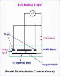
Proud Mary, Mon Jun 11 2012, 01:43PM
I've decided - for constructional reasons, and because I have all the needed parts to hand - to go with the parallel plate ionisation chamber.

Re: Life Below 5 keV
Proud Mary, Mon Jun 11 2012, 06:28PM
Ionisation Chamber Raw Materials
An Affair of Little Boxes
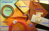
Proud Mary, Mon Jun 11 2012, 06:28PM
Ionisation Chamber Raw Materials
An Affair of Little Boxes

Re: Life Below 5 keV
Proud Mary, Mon Jun 11 2012, 09:04PM
Triaxial Feedthrough Construction
The triaxial feedthrough provides a fully guarded connection from the collector plate through the ionisation chamber wall to the trans impedance amplifier in the box next door.
I drilled down through the centre pin of an SO239 co-axial socket, leaving the walls of the centre pin intact.

I then threaded a length of semi-rigid micro co-ax through the hollow centre of the inner conductor, to create the triaxial feedthrough.
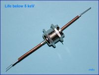
Note: I looked at three different sorts of SO239 socket, and selected one where I could already see a chink of light down the centre of the inner conductor, which made drilling it out the work of seconds. I chose a drill bit the same diameter as the copper sheathing on the semi-rigid co-ax, to make for a snug fit.
I first devised this technique for turning an SO239 socket into a triaxial feedthrough using thin glass capillary tubes (melting point determination tubes) with a fine wire threaded through them, but haven't used the method here because glass isn't such a good dielectric in the fA world, and is easily cracked.
Proud Mary, Mon Jun 11 2012, 09:04PM
Triaxial Feedthrough Construction
The triaxial feedthrough provides a fully guarded connection from the collector plate through the ionisation chamber wall to the trans impedance amplifier in the box next door.
I drilled down through the centre pin of an SO239 co-axial socket, leaving the walls of the centre pin intact.

I then threaded a length of semi-rigid micro co-ax through the hollow centre of the inner conductor, to create the triaxial feedthrough.

Note: I looked at three different sorts of SO239 socket, and selected one where I could already see a chink of light down the centre of the inner conductor, which made drilling it out the work of seconds. I chose a drill bit the same diameter as the copper sheathing on the semi-rigid co-ax, to make for a snug fit.
I first devised this technique for turning an SO239 socket into a triaxial feedthrough using thin glass capillary tubes (melting point determination tubes) with a fine wire threaded through them, but haven't used the method here because glass isn't such a good dielectric in the fA world, and is easily cracked.
Re: Life Below 5 keV
Proud Mary, Tue Jun 12 2012, 11:46PM
I have just learned something I should have known at the outset:
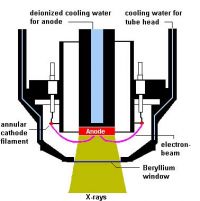
For physical reasons, a proportion of the electrons are always scattered on the surface of the anode. The extent to which these backscattering electrons arise depends, among other factors, on the anode material and can be as much as 40%. In the side-window tube, these backscattering electrons contribute to the heating up of the surrounding material, especially the exit window. As a consequence, the exit window must withstand high levels of thermal stress and cannot be selected with just any thickness. The minimum usable thickness of a beryllium window for side-window tubes is 300 µm. This causes an excessively high absorption of the low-energy characteristic L radiation of the anode material in the exit window and thus a restriction of the excitation of lighter elements in a sample. (In Bruker's Introduction to X-ray Fluorescence)
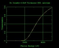
If we assume that the Be window thickness of the two tubes tested so far is 300 µm, as per Bruker, then the transmission of photons below 4.999 keV looks like this:
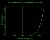
Looking in more detail at the transmission at 2.3 kV - the voltage level at which I was first able to detect photons with the ZP1430 GM tube -we see that only ~6.5% of the photons generated at the anode were actually able to exit the tube.
And of this venturesome 6.5%, only about 65% succeeded in crossing the 1 cm air gap to the detector window, as we see here:
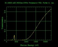
This means that of all the photons generated only about 6.5%*0.65 = 4.2% made it as far as the detector window.
Given that a 300 μm window is practically opaque to photons below 2.0 keV, we see that all the activity detected
can be accounted for by photons in the energy range 2.0 keV - 2.3 keV.
Given that Bruker calls 300 μm "the minimum usable thickness for side-window tubes", and I have no information on the window thickness of the two tubes
tested so far, it may be that this 2.3 kV anode potential represents their absolute rock bottom for getting photons through the window,
and is a limitation of the tube rather than the mica end-window GM detector, which might yet be able to detect photons of lower energy.
More research is needed, as papers never fail to conclude!
Proud Mary, Tue Jun 12 2012, 11:46PM
I have just learned something I should have known at the outset:
For physical reasons, a proportion of the electrons are always scattered on the surface of the anode. The extent to which these backscattering electrons arise depends, among other factors, on the anode material and can be as much as 40%. In the side-window tube, these backscattering electrons contribute to the heating up of the surrounding material, especially the exit window. As a consequence, the exit window must withstand high levels of thermal stress and cannot be selected with just any thickness. The minimum usable thickness of a beryllium window for side-window tubes is 300 µm. This causes an excessively high absorption of the low-energy characteristic L radiation of the anode material in the exit window and thus a restriction of the excitation of lighter elements in a sample. (In Bruker's Introduction to X-ray Fluorescence)
If we assume that the Be window thickness of the two tubes tested so far is 300 µm, as per Bruker, then the transmission of photons below 4.999 keV looks like this:

Looking in more detail at the transmission at 2.3 kV - the voltage level at which I was first able to detect photons with the ZP1430 GM tube -we see that only ~6.5% of the photons generated at the anode were actually able to exit the tube.

And of this venturesome 6.5%, only about 65% succeeded in crossing the 1 cm air gap to the detector window, as we see here:

This means that of all the photons generated only about 6.5%*0.65 = 4.2% made it as far as the detector window.
Given that a 300 μm window is practically opaque to photons below 2.0 keV, we see that all the activity detected
can be accounted for by photons in the energy range 2.0 keV - 2.3 keV.
Given that Bruker calls 300 μm "the minimum usable thickness for side-window tubes", and I have no information on the window thickness of the two tubes
tested so far, it may be that this 2.3 kV anode potential represents their absolute rock bottom for getting photons through the window,
and is a limitation of the tube rather than the mica end-window GM detector, which might yet be able to detect photons of lower energy.
More research is needed, as papers never fail to conclude!

Re: Life Below 5 keV
Proud Mary, Wed Jun 13 2012, 01:19PM
Marking Out the Ionisation Chamber

The interior angle of base to sides is not 90°! The outside angle is a rightangle, but inside the wall thickens slightly towards the base, a common occurrence in diecast metal boxes.
HB pencils can draw directly on the bare metal, but the lines are easily smudged away.
Proud Mary, Wed Jun 13 2012, 01:19PM
Marking Out the Ionisation Chamber

The interior angle of base to sides is not 90°! The outside angle is a rightangle, but inside the wall thickens slightly towards the base, a common occurrence in diecast metal boxes.
HB pencils can draw directly on the bare metal, but the lines are easily smudged away.
Re: Life Below 5 keV
Ash Small, Thu Jun 14 2012, 12:31AM
P.M., just a quick question here, given your knowledge of VT technology, is it possible that a detector built around a PMT 'could' be more sensitive to emissions @ these levels?
Ash Small, Thu Jun 14 2012, 12:31AM
Proud Mary wrote ...
More research is needed, as papers never fail to conclude!
More research is needed, as papers never fail to conclude!

P.M., just a quick question here, given your knowledge of VT technology, is it possible that a detector built around a PMT 'could' be more sensitive to emissions @ these levels?
Re: Life Below 5 keV
Proud Mary, Thu Jun 14 2012, 09:55AM
Ah, now I think I understand what you meant in an earlier question about 'weak' x-rays.
The dosimetry problem here isn't the same as, for example, trying to detect radiation from typical 'weak' amateur sources such as thoriated gas mantles and uranium glass marbles, where quite energetic rays and particles are emitted - but in the small or 'weak' quantities appropriate for consumer goods. These can be detected and measured with an ionisation chamber, but it wouldn't normally be first choice.
Now, in our case, we have no shortage of low energy photons <4.999 keV. Our sources are very bright, and at the short ranges used in these experiments have a high fluence - a high number of photons per square centimeter. To put this in perspective, the dose rate 1 cm from a thoriated gas mantle will be just a few micrograys an hour (μGy/hr) while the dose rate below 4.999 keV of a hefty electron-impact source like BSV-25 at the same distance will be in the kilogray per hour regime (kGy/hr) so that care must be taken if adverse events are to be avoided.
Now back to your PMT question. Measuring pulse height at energies below about 10 keV with a thallium-doped sodium iodide scintillator (NaI/Tl) is difficult - but not impossible - because of the short attenuation length of Grenz ray absorption, with all the impinging photons being absorbed extremely close to the scintillator surface. If this problem can be overcome, then there is the problem of detector saturation - the zillion zillion scintillations per second produced by kilogray absorption would require specially built equipment - which is why ionisation chambers are almost always first choice for measuring x-ray and gamma ray beams. There are no 'pulse pile-up' or 'dead time' issues with an ionisation chamber.
Because the ionisation chamber deals with primary physical concepts - one Gray being the the absorption of one joule of ionising radiation energy by one kilogram of matter - it is the standard against which all other dosimetry is calibrated, so-called 'reference ionisation chambers' being kept in the vaults of the Bureau of Standards in Paris.
And finally, I don't have an NaI/Tl crystal!
Proud Mary, Thu Jun 14 2012, 09:55AM
Ash Small wrote ...
P.M., just a quick question here, given your knowledge of VT technology, is it possible that a detector built around a PMT 'could' be more sensitive to emissions @ these levels?
Proud Mary wrote ...
More research is needed, as papers never fail to conclude!
More research is needed, as papers never fail to conclude!

P.M., just a quick question here, given your knowledge of VT technology, is it possible that a detector built around a PMT 'could' be more sensitive to emissions @ these levels?
Ah, now I think I understand what you meant in an earlier question about 'weak' x-rays.
The dosimetry problem here isn't the same as, for example, trying to detect radiation from typical 'weak' amateur sources such as thoriated gas mantles and uranium glass marbles, where quite energetic rays and particles are emitted - but in the small or 'weak' quantities appropriate for consumer goods. These can be detected and measured with an ionisation chamber, but it wouldn't normally be first choice.
Now, in our case, we have no shortage of low energy photons <4.999 keV. Our sources are very bright, and at the short ranges used in these experiments have a high fluence - a high number of photons per square centimeter. To put this in perspective, the dose rate 1 cm from a thoriated gas mantle will be just a few micrograys an hour (μGy/hr) while the dose rate below 4.999 keV of a hefty electron-impact source like BSV-25 at the same distance will be in the kilogray per hour regime (kGy/hr) so that care must be taken if adverse events are to be avoided.
Now back to your PMT question. Measuring pulse height at energies below about 10 keV with a thallium-doped sodium iodide scintillator (NaI/Tl) is difficult - but not impossible - because of the short attenuation length of Grenz ray absorption, with all the impinging photons being absorbed extremely close to the scintillator surface. If this problem can be overcome, then there is the problem of detector saturation - the zillion zillion scintillations per second produced by kilogray absorption would require specially built equipment - which is why ionisation chambers are almost always first choice for measuring x-ray and gamma ray beams. There are no 'pulse pile-up' or 'dead time' issues with an ionisation chamber.
Because the ionisation chamber deals with primary physical concepts - one Gray being the the absorption of one joule of ionising radiation energy by one kilogram of matter - it is the standard against which all other dosimetry is calibrated, so-called 'reference ionisation chambers' being kept in the vaults of the Bureau of Standards in Paris.
And finally, I don't have an NaI/Tl crystal!

Re: Life Below 5 keV
Proud Mary, Thu Jun 14 2012, 03:19PM
Ionisation Chamber First Fixings
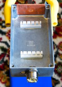
The triaxial feedthrough, the ceramic supports for the collector plate, and the copper mesh faradic screen over the photon port are now in place.
Proud Mary, Thu Jun 14 2012, 03:19PM
Ionisation Chamber First Fixings

The triaxial feedthrough, the ceramic supports for the collector plate, and the copper mesh faradic screen over the photon port are now in place.
Re: Life Below 5 keV
plazmatron, Thu Jun 14 2012, 03:20PM
@Ash,
I suppose one could coat a microscopically thin layer of a suitable Scintillator onto a PMT, and while technically possible, I would imagine it would be very expensive.
I think the main reason this has not been done, is that very little research has been carried out at sub 5KeV levels.
Ion chambers of one sort or another have been around since the dawn of x-ray technology, and as Proud Mary says, much is known about them. Using standard 'knowns' is an important practice when investigating virgin territory like this.
@Proud Mary,
very nice work on the chamber

Re: Life Below 5 keV
Proud Mary, Thu Jun 14 2012, 05:43PM
Ionisation Chamber Collector Plate
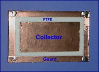

The etched face of the PTFE slab will take epoxy for glueing to the ceramic hurdles.
The self-adhesive copper foil adheres only lightly to the PTFE surface, so I carried the guard on right round the bottom and tacked the corners together with solder, so it is strapped down as well as glued now.
I used a 25W iron with Ersin Multi Core lead/tin solder for this job, and found the solder flowed quickly enough to stop the adhesive on the copper playing up, which I was afraid it might try to do, given the chance.
@Les - yes, it's wonderful that the world below 5 keV was almost ignored until quite recently - not like some wretched old lamp post upon which fifty generations of dogs have already made their mark!
Proud Mary, Thu Jun 14 2012, 05:43PM
Ionisation Chamber Collector Plate


The etched face of the PTFE slab will take epoxy for glueing to the ceramic hurdles.
The self-adhesive copper foil adheres only lightly to the PTFE surface, so I carried the guard on right round the bottom and tacked the corners together with solder, so it is strapped down as well as glued now.
I used a 25W iron with Ersin Multi Core lead/tin solder for this job, and found the solder flowed quickly enough to stop the adhesive on the copper playing up, which I was afraid it might try to do, given the chance.
@Les - yes, it's wonderful that the world below 5 keV was almost ignored until quite recently - not like some wretched old lamp post upon which fifty generations of dogs have already made their mark!

Re: Life Below 5 keV
Ash Small, Thu Jun 14 2012, 07:01PM
@ Les: Yes. I realise the simplicity of the ion chamber. It's just that after PM's comments about only ~6.5% of radiation will make it into the chamber at these energy levels I was wondering if it was possible to use a pmt with suitable scintillator. I appreciate the biggest hurdle would be obtaining a suitable scintillator. Things like NaI/Tl crystals do turn up occasionally on E-bay.
@PM: Could photographic paper not be used as a simple guage of emissions @ various energy levels? (or even digital camera technology?)
BTW, very nice work!

Re: Life Below 5 keV
Proud Mary, Thu Jun 14 2012, 07:38PM
Perhaps I haven't done a good job of making myself clear, Mr Ash. I intended to make clear that at 2.3 keV, only 6.5% of the total photons generated at the anode ever managed to escape through the beryllium window of the Grenz generator. And these survivors suffered a further 35% loss just traveling through 1 cm of air, so that only 4.2% of the original photons were available to interact with whatever kind of detector you put there.
One advantage the free air ionisation chamber has over almost all other detectors - including NaI/Tl* - is that it doesn't need a window of any kind that would produce further losses.
I will be looking at direct digital imaging when all the basic apparatus and instruments have been taken care of. I have to make everything up as I go along, so don't hold your breath!
*NaI/Tl is hygroscopic, so must be operated in an anhydrous atmosphere with a beryllium or aluminium window.
Proud Mary, Thu Jun 14 2012, 07:38PM
Ash Small wrote ...
@ Les: Yes. I realise the simplicity of the ion chamber. It's just that after PM's comments about only ~6.5% of radiation will make it into the chamber at these energy levels I was wondering if it was possible to use a pmt with suitable scintillator. I appreciate the biggest hurdle would be obtaining a suitable scintillator. Things like NaI/Tl crystals do turn up occasionally on E-bay.
@PM: Could photographic paper not be used as a simple guage of emissions @ various energy levels? (or even digital camera technology?)
BTW, very nice work!

Perhaps I haven't done a good job of making myself clear, Mr Ash. I intended to make clear that at 2.3 keV, only 6.5% of the total photons generated at the anode ever managed to escape through the beryllium window of the Grenz generator. And these survivors suffered a further 35% loss just traveling through 1 cm of air, so that only 4.2% of the original photons were available to interact with whatever kind of detector you put there.
One advantage the free air ionisation chamber has over almost all other detectors - including NaI/Tl* - is that it doesn't need a window of any kind that would produce further losses.
I will be looking at direct digital imaging when all the basic apparatus and instruments have been taken care of. I have to make everything up as I go along, so don't hold your breath!

*NaI/Tl is hygroscopic, so must be operated in an anhydrous atmosphere with a beryllium or aluminium window.
Re: Life Below 5 keV
Proud Mary, Thu Jun 14 2012, 08:00PM
pressed the wrong button!
Proud Mary, Thu Jun 14 2012, 08:00PM
pressed the wrong button!
Re: Life Below 5 keV
plazmatron, Thu Jun 14 2012, 08:07PM
Sure! In fact I use small piece of photographic paper all the time to test at these low kVp levels. It has the added advantage providing you with a beam profile too, which is very handy as far as imaging goes.
Film may be faster, however my shed is far from dark enough, paper is fast enough, and the white background provides good contrast for making quick observations.
As far as silicon is concerned, I suspect it would make a wholly suitable detector, since all of the photons that arrive at the chip, will deposit their energy at the surface. I would guess even the bare silicon layer of a photodiode, or solar cell, would make an adequate detector.
Les
plazmatron, Thu Jun 14 2012, 08:07PM
Ash Small wrote ...
Could photographic paper not be used as a simple guage of emissions @ various energy levels? (or even digital camera technology?)
Could photographic paper not be used as a simple guage of emissions @ various energy levels? (or even digital camera technology?)
Sure! In fact I use small piece of photographic paper all the time to test at these low kVp levels. It has the added advantage providing you with a beam profile too, which is very handy as far as imaging goes.
Film may be faster, however my shed is far from dark enough, paper is fast enough, and the white background provides good contrast for making quick observations.
As far as silicon is concerned, I suspect it would make a wholly suitable detector, since all of the photons that arrive at the chip, will deposit their energy at the surface. I would guess even the bare silicon layer of a photodiode, or solar cell, would make an adequate detector.
Les
Re: Life Below 5 keV
Ash Small, Fri Jun 15 2012, 09:13AM
Aaah, that certainly clarifies things, PM.
I simply wondered what the obstacles were to using a PMT @ these low energy levels, compared to the ionization chamber, or other methods.
Ash Small, Fri Jun 15 2012, 09:13AM
Proud Mary wrote ...
Perhaps I haven't done a good job of making myself clear, Mr Ash. I intended to make clear that at 2.3 keV, only 6.5% of the total photons generated at the anode ever managed to escape through the beryllium window of the Grenz generator. And these survivors suffered a further 65% loss just traveling through 1 cm of air, so that only 4.2% of the original photons were available to interact with whatever kind of detector you put there.
One advantage the free air ionisation chamber has over almost all other detectors - including NaI/Tl* - is that it doesn't need a window of any kind that would produce further losses.
I will be looking at direct digital imaging when all the basic apparatus and instruments have been taken care of. I have to make everything up as I go along, so don't hold your breath!
*NaI/Tl is hygroscopic, so must be operated in an anhydrous atmosphere with a beryllium or aluminium window.
Perhaps I haven't done a good job of making myself clear, Mr Ash. I intended to make clear that at 2.3 keV, only 6.5% of the total photons generated at the anode ever managed to escape through the beryllium window of the Grenz generator. And these survivors suffered a further 65% loss just traveling through 1 cm of air, so that only 4.2% of the original photons were available to interact with whatever kind of detector you put there.
One advantage the free air ionisation chamber has over almost all other detectors - including NaI/Tl* - is that it doesn't need a window of any kind that would produce further losses.
I will be looking at direct digital imaging when all the basic apparatus and instruments have been taken care of. I have to make everything up as I go along, so don't hold your breath!

*NaI/Tl is hygroscopic, so must be operated in an anhydrous atmosphere with a beryllium or aluminium window.
Aaah, that certainly clarifies things, PM.
I simply wondered what the obstacles were to using a PMT @ these low energy levels, compared to the ionization chamber, or other methods.
Re: Life Below 5 keV
Proud Mary, Fri Jun 15 2012, 09:51AM
Haha, I didn't make myself clear at all!
When I wrote that
"I intended to make clear that at 2.3 keV, only 6.5% of the total photons generated at the anode ever managed to escape through the beryllium window of the Grenz generator. And these survivors suffered a further 65% loss just traveling through 1 cm of air, so that only 4.2% of the original photons were available to interact with whatever kind of detector you put there."
I should have said "survivors suffered a further 35% loss just traveling through 1 cm of air" i.e. that 65% got through the 1 cm of air.
I will go back and edit the original so readers aren't further mislead.
Re: Life Below 5 keV
Proud Mary, Fri Jun 15 2012, 10:59AM
Collector Plate Assembly
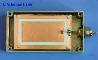
The copper foil on the collector has lifted slightly around the soldering, so I have dropped 'superglue' down the triaxial feedthrough - where the semi-rigid co-ax passes through it - to forestall any movement that might result in a tear.
Proud Mary, Fri Jun 15 2012, 10:59AM
Collector Plate Assembly

The copper foil on the collector has lifted slightly around the soldering, so I have dropped 'superglue' down the triaxial feedthrough - where the semi-rigid co-ax passes through it - to forestall any movement that might result in a tear.
Re: Life Below 5 keV
Proud Mary, Fri Jun 15 2012, 12:18PM
Hamamatsu L11757
Hamamatsu have used an ionization chamber to plot the air ion discharge gradient produced by their new 4.9 kV Grenz source.

Proud Mary, Fri Jun 15 2012, 12:18PM
Hamamatsu L11757
Hamamatsu have used an ionization chamber to plot the air ion discharge gradient produced by their new 4.9 kV Grenz source.

Re: Life Below 5 keV
Proud Mary, Sat Jun 16 2012, 05:19PM
Charging Electrode and Double Box Details
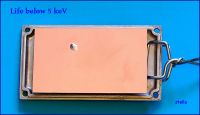
The solder spot is the through-hole termination of the bias input lead.
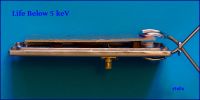
I used the same standoff arrangements used for the collector plate.

I will divide the electronics box into decoupled compartments so electrons can't start making their own unofficial and unapproved
voyages around the circuit.
Proud Mary, Sat Jun 16 2012, 05:19PM
Charging Electrode and Double Box Details

The solder spot is the through-hole termination of the bias input lead.

I used the same standoff arrangements used for the collector plate.

I will divide the electronics box into decoupled compartments so electrons can't start making their own unofficial and unapproved
voyages around the circuit.
Re: Life Below 5 keV
Sulaiman, Sat Jun 16 2012, 06:44PM
I've been following this project with some interest,
had a thought,
at the ,5 keV range I think that the wavelength of x-ray photons will be of the same order as the atomic spacing of many solids (or am I way out?)
which means solids may act as bandpass filters etc?
Re: Life Below 5 keV
Proud Mary, Sat Jun 16 2012, 08:20PM
If we first consider the case of visible light, diffraction occurs in a diffraction grating when the spaces between the lines are of the same order as the wavelength of the arriving light - a few thousand Angstroms.
The interatomic spaces in crystalline solids are conveniently of the same order as x-ray wavelengths, so the rays can be diffracted by the repeating patterns of atoms, a fact from which the huge field of x-ray diffraction has evolved since its discovery by Laue in 1912 - a hundred years ago.
A crystalline solid can disperse x-rays according to wavelength (Bragg's Law), just as as a diffraction grating can disperse white light into the colours of the rainbow. This makes it possible to select a particular wavelength, a process used in monochromators to produce (ideally) x-rays of a single wavelength.
None of this is peculiar to the ultra-soft, and I am wondering if you are thinking either of the famous x-ray 'water window' - 280 to 530 eV - which is at the heart of x-ray microscopy of biological specimens, or of the strange and marvellous world of x-ray optics with its multi-layer mirrors and lenses formed from
exotic materials.
This project thread is very much about learning as I go along, so perhaps I'll be able to give you a much better answer later on. There's always hope!
Proud Mary, Sat Jun 16 2012, 08:20PM
Sulaiman wrote ...
I've been following this project with some interest,
had a thought,
at the ,5 keV range I think that the wavelength of x-ray photons will be of the same order as the atomic spacing of many solids (or am I way out?)
which means solids may act as bandpass filters etc?
I've been following this project with some interest,
had a thought,
at the ,5 keV range I think that the wavelength of x-ray photons will be of the same order as the atomic spacing of many solids (or am I way out?)
which means solids may act as bandpass filters etc?
If we first consider the case of visible light, diffraction occurs in a diffraction grating when the spaces between the lines are of the same order as the wavelength of the arriving light - a few thousand Angstroms.
The interatomic spaces in crystalline solids are conveniently of the same order as x-ray wavelengths, so the rays can be diffracted by the repeating patterns of atoms, a fact from which the huge field of x-ray diffraction has evolved since its discovery by Laue in 1912 - a hundred years ago.
A crystalline solid can disperse x-rays according to wavelength (Bragg's Law), just as as a diffraction grating can disperse white light into the colours of the rainbow. This makes it possible to select a particular wavelength, a process used in monochromators to produce (ideally) x-rays of a single wavelength.
None of this is peculiar to the ultra-soft, and I am wondering if you are thinking either of the famous x-ray 'water window' - 280 to 530 eV - which is at the heart of x-ray microscopy of biological specimens, or of the strange and marvellous world of x-ray optics with its multi-layer mirrors and lenses formed from
exotic materials.
This project thread is very much about learning as I go along, so perhaps I'll be able to give you a much better answer later on. There's always hope!

Re: Life Below 5 keV
Proud Mary, Mon Jun 18 2012, 03:33PM
The 40GΩ resistor that calls itself 50GΩ
After having promised myself that I was going to have nothing to do with resistors of prodigious value, I found that the current noise in my T-bridge mod to the trans impedance amplifier was worse than a resistor of 50GΩ.
Reluctantly, I turned back to the resistors of prodigious value, which it turns out are also of prodigious cost if you want a human-friendly wire-ended one. Like £50 each!
This left me with only 0805 size chip resistors of which I found I had ten that had apparently cost me £1.72 each - still a ludicrous price for something the size of tea leaf. Looking at them in their packaging tape, I wasn't surprised I'd forgotten I had them. No one but a dalek could actually like them.
Anyway, I stuck two strips of copper tape onto a piece of PTFE about 1mm apart, and put spots of solder onto each of them. Using tweezers, I then set a chip resistor as a bridge between the two foil strips, and applied a 15W soldering iron.
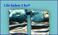
The resistor is 2mm from end to end
I was very dubious about this arrangement which has all the hallmarks of a real bodge, so I measured the resistance between the two foils with my Takeda Riken TR8601 High Ohm Meter, and found it to be 40GΩ - certainly less than I was hoping for, even at £1.72.
This made me go back to the product data, where I found that the tolerance of these chip resistors is only 30% - so my measured 40GΩ was within spec so far as the manufacturer was concerned:
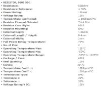
And if I really wanted 50GΩ 1%, then there was always this season's range of exclusive Ohmite glass through-hole resistors starting at £49.58. Naturally, I decided that I had really wanted 40GΩ all along...
Proud Mary, Mon Jun 18 2012, 03:33PM
The 40GΩ resistor that calls itself 50GΩ
After having promised myself that I was going to have nothing to do with resistors of prodigious value, I found that the current noise in my T-bridge mod to the trans impedance amplifier was worse than a resistor of 50GΩ.
Reluctantly, I turned back to the resistors of prodigious value, which it turns out are also of prodigious cost if you want a human-friendly wire-ended one. Like £50 each!
This left me with only 0805 size chip resistors of which I found I had ten that had apparently cost me £1.72 each - still a ludicrous price for something the size of tea leaf. Looking at them in their packaging tape, I wasn't surprised I'd forgotten I had them. No one but a dalek could actually like them.
Anyway, I stuck two strips of copper tape onto a piece of PTFE about 1mm apart, and put spots of solder onto each of them. Using tweezers, I then set a chip resistor as a bridge between the two foil strips, and applied a 15W soldering iron.

The resistor is 2mm from end to end
I was very dubious about this arrangement which has all the hallmarks of a real bodge, so I measured the resistance between the two foils with my Takeda Riken TR8601 High Ohm Meter, and found it to be 40GΩ - certainly less than I was hoping for, even at £1.72.
This made me go back to the product data, where I found that the tolerance of these chip resistors is only 30% - so my measured 40GΩ was within spec so far as the manufacturer was concerned:

And if I really wanted 50GΩ 1%, then there was always this season's range of exclusive Ohmite glass through-hole resistors starting at £49.58. Naturally, I decided that I had really wanted 40GΩ all along...
Re: Life Below 5 keV
plazmatron, Mon Jun 18 2012, 04:54PM
Rather you than me!
How do you intend to protect that tiny resistor from surface leakage, or any kind of surface contamination?
I have always found high value resistors like this, quite a challenge to work with.
Ha! Frequently my projects are driven by outcomes like this, and sometimes by serendipity...
Les
plazmatron, Mon Jun 18 2012, 04:54PM
Rather you than me!
How do you intend to protect that tiny resistor from surface leakage, or any kind of surface contamination?
I have always found high value resistors like this, quite a challenge to work with.
Proud Mary wrote ...
Naturally, I decided that I had really wanted 40GΩ all along...
Naturally, I decided that I had really wanted 40GΩ all along...
Ha! Frequently my projects are driven by outcomes like this, and sometimes by serendipity...
Les
Re: Life Below 5 keV
Proud Mary, Mon Jun 18 2012, 05:34PM
I discovered that the resistance was 35GΩ at 100V, 37GΩ at 50V and 40GΩ at 10V - these are the kind of figures you get with gigohm resistances when a guard is not used to mitigate surface leakage. The size of the thing made it impossible to wrap a wire round it and take it to the meter's guard output, so we should take it that 40G is the total resistance of the part in parallel with the (possibly variable) leakage paths on the outside.
As for surface contamination, the resistor will be operating inside a sealed, dessicated box, but I don't find this very reassuring.
I may coat the resistor and its surrounds with clear acrylic nail polish, and then measure its resistance again when the varnish has hardened, to see if it is still usable.
I have worked out that a 10GΩ resistor will just do if I upgrade the amplifier. I've sent off for a rather large 10GΩ 3W 5% resistor for £3.11 inc p&p, so that I have a standby if the 40GΩ starts to drift, or doesn't recover from its nail polish make-over.
Proud Mary, Mon Jun 18 2012, 05:34PM
plazmatron wrote ...
Rather you than me!
How do you intend to protect that tiny resistor from surface leakage, or any kind of surface contamination?
I have always found high value resistors like this, quite a challenge to work with.
Ha! Frequently my projects are driven by outcomes like this, and sometimes by serendipity...
Les
Rather you than me!
How do you intend to protect that tiny resistor from surface leakage, or any kind of surface contamination?
I have always found high value resistors like this, quite a challenge to work with.
Proud Mary wrote ...
Naturally, I decided that I had really wanted 40GΩ all along...
Naturally, I decided that I had really wanted 40GΩ all along...
Ha! Frequently my projects are driven by outcomes like this, and sometimes by serendipity...
Les
I discovered that the resistance was 35GΩ at 100V, 37GΩ at 50V and 40GΩ at 10V - these are the kind of figures you get with gigohm resistances when a guard is not used to mitigate surface leakage. The size of the thing made it impossible to wrap a wire round it and take it to the meter's guard output, so we should take it that 40G is the total resistance of the part in parallel with the (possibly variable) leakage paths on the outside.
As for surface contamination, the resistor will be operating inside a sealed, dessicated box, but I don't find this very reassuring.
I may coat the resistor and its surrounds with clear acrylic nail polish, and then measure its resistance again when the varnish has hardened, to see if it is still usable.
I have worked out that a 10GΩ resistor will just do if I upgrade the amplifier. I've sent off for a rather large 10GΩ 3W 5% resistor for £3.11 inc p&p, so that I have a standby if the 40GΩ starts to drift, or doesn't recover from its nail polish make-over.
Re: Life Below 5 keV
radhoo, Sat Jun 23 2012, 09:11PM
great design on the ion chamber, and a very interesting project that I hoped for a long time to see happening.
once you get over the high ohmic resistor issues, and get the tiny ion chamber current (well, maybe not so tiny at the x-ray intensity you are going to generate) translated into a measurable voltage, how do you plan to amplify that while keeping noise down?
already having a suitable Op amp in mind?
Re: Life Below 5 keV
Proud Mary, Sat Jun 23 2012, 09:31PM
I'm working on it right now, Radhu! I've tried several designs so far. At the moment, I'm trying an FET source follower with a constant current BJT in the source lead, to get a gain hopefully >0.99 and ultra-high impedance. Then I will have a two stage amplifier - either OPA177 or OPA200 - because I have some of both. Once I have something that is stable, I will add refinements, one at a time, to see how I can improve it.
Proud Mary, Sat Jun 23 2012, 09:31PM
radhoo wrote ...
great design on the ion chamber, and a very interesting project that I hoped for a long time to see happening.
once you get over the high ohmic resistor issues, and get the tiny ion chamber current (well, maybe not so tiny at the x-ray intensity you are going to generate) translated into a measurable voltage, how do you plan to amplify that while keeping noise down?
already having a suitable Op amp in mind?
I'm working on it right now, Radhu!
 I've tried several designs so far. At the moment, I'm trying an FET source follower with a constant current BJT in the source lead, to get a gain hopefully >0.99 and ultra-high impedance. Then I will have a two stage amplifier - either OPA177 or OPA200 - because I have some of both. Once I have something that is stable, I will add refinements, one at a time, to see how I can improve it.
 Re: Life Below 5 keV
Proud Mary, Sun Jun 24 2012, 03:00PM
Glass stand-off insulators
This is how I make glass stand-off insulators using 4mm glass beads and 6mm self-adhesive copper tape. The glass beads cost 99p (EUR 1.24) per 100.
A 5mm punch cuts copper foil disks just the right size to stick on top of the 4mm glass beads. A block of hard wood placed under the copper foil,
and good sharp tap of the hammer, helps to ensure a clean cut. The cut discs go up inside the barrel of the punch, and have to be pushed out in a
column like a core bore through sedimenatry rock. A few of them get damaged in the prcoess.

It can be a bit fiddly peeling off the self-adhesive backing, but a scalpel blade will easily lift an edge.
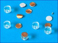
The completed stand-offs are ready to be stuck to the PCB copper ground plane with 5-minute epoxy.
Proud Mary, Sun Jun 24 2012, 03:00PM
Glass stand-off insulators
This is how I make glass stand-off insulators using 4mm glass beads and 6mm self-adhesive copper tape. The glass beads cost 99p (EUR 1.24) per 100.
A 5mm punch cuts copper foil disks just the right size to stick on top of the 4mm glass beads. A block of hard wood placed under the copper foil,
and good sharp tap of the hammer, helps to ensure a clean cut. The cut discs go up inside the barrel of the punch, and have to be pushed out in a
column like a core bore through sedimenatry rock. A few of them get damaged in the prcoess.

It can be a bit fiddly peeling off the self-adhesive backing, but a scalpel blade will easily lift an edge.

The completed stand-offs are ready to be stuck to the PCB copper ground plane with 5-minute epoxy.
Re: Life Below 5 keV
IntraWinding, Mon Jun 25 2012, 05:42PM
Could you direct backscattering electrons away from your Beryllium window by applying to it a suitably large negative bias voltage, reducing the heating effect and thus enabling a thinner window to be used?
IntraWinding, Mon Jun 25 2012, 05:42PM
Could you direct backscattering electrons away from your Beryllium window by applying to it a suitably large negative bias voltage, reducing the heating effect and thus enabling a thinner window to be used?
Re: Life Below 5 keV
Proud Mary, Mon Jun 25 2012, 09:14PM
That is indeed the modus operandi of most end-window tubes, where backscatter is steered back to the anode, and so is removed from the window's thermal budget.
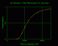
In practice, this means that Be windows of as thin as 75 µm can be used, so much longer wavelengths can exit the tube.
As you see in this graph, the 75 µm window is able to transmit useful amounts of photons down to about 1.5 keV, whereas the 300 µm side windows were found to be effectively opaque below 2.3 keV in my first experiments above.
Needless to say, I have several end-window tubes whose emissions below 2.3 keV I will be investigating in this thread once I've sorted out the ionisation chamber to detect them.
Proud Mary, Mon Jun 25 2012, 09:14PM
IntraWinding wrote ...
Could you direct backscattering electrons away from your Beryllium window by applying to it a suitably large negative bias voltage, reducing the heating effect and thus enabling a thinner window to be used?
Could you direct backscattering electrons away from your Beryllium window by applying to it a suitably large negative bias voltage, reducing the heating effect and thus enabling a thinner window to be used?
That is indeed the modus operandi of most end-window tubes, where backscatter is steered back to the anode, and so is removed from the window's thermal budget.

In practice, this means that Be windows of as thin as 75 µm can be used, so much longer wavelengths can exit the tube.
As you see in this graph, the 75 µm window is able to transmit useful amounts of photons down to about 1.5 keV, whereas the 300 µm side windows were found to be effectively opaque below 2.3 keV in my first experiments above.

Needless to say, I have several end-window tubes whose emissions below 2.3 keV I will be investigating in this thread once I've sorted out the ionisation chamber to detect them.
Re: Life Below 5 keV
Proud Mary, Tue Jun 26 2012, 10:29AM
From Russia With Love
Arrived in the post this morning.
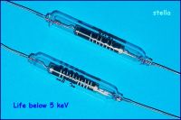
10 GΩ resistors - body length 45mm
I measured these with the Takeda Riken, and they both came in at 10.7 GΩ - so they're throwing in a free 700 MΩ with each resistor!
Now I have the dimensions, I can get on with the circuit layout.
Proud Mary, Tue Jun 26 2012, 10:29AM
From Russia With Love
Arrived in the post this morning.

10 GΩ resistors - body length 45mm
I measured these with the Takeda Riken, and they both came in at 10.7 GΩ - so they're throwing in a free 700 MΩ with each resistor!

Now I have the dimensions, I can get on with the circuit layout.
Re: Life Below 5 keV
Proud Mary, Wed Jun 27 2012, 12:03AM
TIA Circuit No. 3
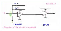
This circuit is about getting the femtoamps to queue in an orderly line and not drift off while they are being counted. It's not much different to
the circuit with which I started, and changes - anti-drift measures - have been about lay-out, mechanical stability, cleanliness, and the dielectric properties of materials.
Proud Mary, Wed Jun 27 2012, 12:03AM
TIA Circuit No. 3

This circuit is about getting the femtoamps to queue in an orderly line and not drift off while they are being counted. It's not much different to
the circuit with which I started, and changes - anti-drift measures - have been about lay-out, mechanical stability, cleanliness, and the dielectric properties of materials.
Re: Life Below 5 keV
Proud Mary, Mon Jul 02 2012, 11:32AM
I am on my summer holiday and will put up the photos of the prototype front end board when I get back.
In the meantime:
Proud Mary, Mon Jul 02 2012, 11:32AM
I am on my summer holiday and will put up the photos of the prototype front end board when I get back.
In the meantime:

Re: Life Below 5 keV
radhoo, Mon Jul 09 2012, 02:02PM
what's the tolerance for those high ohmic resistors?
when I last checked ebay, I could only find 5% tolerance resistors.
ps: make that from russia with love for money :)
radhoo, Mon Jul 09 2012, 02:02PM
what's the tolerance for those high ohmic resistors?
when I last checked ebay, I could only find 5% tolerance resistors.
ps: make that from russia with love for money :)
Re: Life Below 5 keV
Proud Mary, Sun Jul 15 2012, 11:26PM
Just a very quick reply as I am still away on holiday. The tolerance on the resistors was determined empirically by me to be +7.0 % using a Tadeka Riken high ohm meter with a guard electrode wound round the outside of the glass tubes after cleaning with methanol and baking. Sample was n = 2. That's all I know, Radhu!
Proud Mary, Sun Jul 15 2012, 11:26PM
radhoo wrote ...
what's the tolerance for those high ohmic resistors?
when I last checked ebay, I could only find 5% tolerance resistors.
ps: make that from russia with love for money :)
what's the tolerance for those high ohmic resistors?
when I last checked ebay, I could only find 5% tolerance resistors.
ps: make that from russia with love for money :)
Just a very quick reply as I am still away on holiday. The tolerance on the resistors was determined empirically by me to be +7.0 % using a Tadeka Riken high ohm meter with a guard electrode wound round the outside of the glass tubes after cleaning with methanol and baking. Sample was n = 2. That's all I know, Radhu!

Re: Life Below 5 keV
Conundrum, Sat Aug 11 2012, 08:47AM
Just a thought, what about immersing the resistor in dry vegetable oil?
That ought to work, at least for a while.
-A
Conundrum, Sat Aug 11 2012, 08:47AM
Just a thought, what about immersing the resistor in dry vegetable oil?
That ought to work, at least for a while.
-A
Re: Life Below 5 keV
radhoo, Wed Nov 07 2012, 09:23AM
Hi Stella,
It seems we now share a common goal, as I also plan to build a ion chamber - at first just for testing and learning, as I know almost nothing about this field. Judging from my Geiger Counters experience, I expect this to be challenging as well.
I got myself nice 100G and 1000G glass resistors, with a few more on the way (had some luck finding them, as someone scrapped those from working equipment). I'll be starting a new thread, to keep this one clean, but I would surely love to see this thread revitalized.
Re: Life Below 5 keV
Proud Mary, Wed Nov 07 2012, 07:19PM
Hi Radhu,
I haven't made much progress with this because I have had to put a lot of work into other areas of my life, as we all have to do sometimes.
I have had especial difficulty with reliable dosimetry below 4.99 keV using the standard ionisation chamber configurations, and was wondering what to do until I re-read the details of this Hamamatsu ultra-soft source.
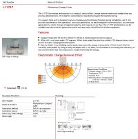
Notice that the measuring device is nothing more than a metal plate 150mm*150mm of capacitance 20 pF charged to 1 kV. Hamamatsu is a world leader in radiation sensor technology, yet they are using what is basically a gold leaf electroscope for measurements below 4.9 keV!
I guessed that the distance between Hamamatsu's plate and a second plate must be 10mm, and that is what it turns out to be where
C= K*Eo*A/D, where Eo= 8.854x10⁻¹²
where:
K is 1.00054
A is 22500 mm²
d is 10mm distance to a second plate of equal area.
C is 19.9 pF - the capacitance between the two plates.
If it's good enough for Hamamatsu, it's good enough for me, so I've started to look at the problem from this new direction, and hope to have something to show you and Plazmatron by Christmas.
All the best, Stella.
Proud Mary, Wed Nov 07 2012, 07:19PM
Hi Radhu,
I haven't made much progress with this because I have had to put a lot of work into other areas of my life, as we all have to do sometimes.
I have had especial difficulty with reliable dosimetry below 4.99 keV using the standard ionisation chamber configurations, and was wondering what to do until I re-read the details of this Hamamatsu ultra-soft source.

Notice that the measuring device is nothing more than a metal plate 150mm*150mm of capacitance 20 pF charged to 1 kV. Hamamatsu is a world leader in radiation sensor technology, yet they are using what is basically a gold leaf electroscope for measurements below 4.9 keV!
I guessed that the distance between Hamamatsu's plate and a second plate must be 10mm, and that is what it turns out to be where
C= K*Eo*A/D, where Eo= 8.854x10⁻¹²
where:
K is 1.00054
A is 22500 mm²
d is 10mm distance to a second plate of equal area.
C is 19.9 pF - the capacitance between the two plates.
If it's good enough for Hamamatsu, it's good enough for me, so I've started to look at the problem from this new direction, and hope to have something to show you and Plazmatron by Christmas.
All the best, Stella.

Re: Life Below 5 keV
radhoo, Sun Jun 09 2013, 04:07PM
Hi Stella!
I was wondering if you managed to invest more time into this , for some additional progress?
radhoo, Sun Jun 09 2013, 04:07PM
Hi Stella!
I was wondering if you managed to invest more time into this , for some additional progress?
Re: Life Below 5 keV
Proud Mary, Sun Jun 09 2013, 06:23PM
Hi there Radhu - yes, I found that a conventional old-fashioned school electroscope could lose charge and so detect 2 keV photons, though as ranges grow shorter it becomes difficult to prevent interaction between the photon source housing and the charge plate.
Despite the obvious problem with air humidity/insulator leakage, I found the electroscope good for making relative measurements, so long as the experimental conditions are kept as nearly identical as possible.
A radiating 2X2 makes the leaves collapse in a second or two!
Proud Mary, Sun Jun 09 2013, 06:23PM
radhoo wrote ...
Hi Stella!
I was wondering if you managed to invest more time into this , for some additional progress?
Hi Stella!
I was wondering if you managed to invest more time into this , for some additional progress?
Hi there Radhu - yes, I found that a conventional old-fashioned school electroscope could lose charge and so detect 2 keV photons, though as ranges grow shorter it becomes difficult to prevent interaction between the photon source housing and the charge plate.
Despite the obvious problem with air humidity/insulator leakage, I found the electroscope good for making relative measurements, so long as the experimental conditions are kept as nearly identical as possible.
A radiating 2X2 makes the leaves collapse in a second or two!

Re: Life Below 5 keV
Conundrum, Sun Jun 09 2013, 07:22PM
Hi everyone, has anyone tried using PG (pyrolytic graphite) as a window material, if it is transparent to alpha particles then X-rays should go right through it.
-A
Conundrum, Sun Jun 09 2013, 07:22PM
Hi everyone, has anyone tried using PG (pyrolytic graphite) as a window material, if it is transparent to alpha particles then X-rays should go right through it.
-A
Re: Life Below 5 keV
Proud Mary, Sun Jun 09 2013, 07:58PM
Graphite is commonly used in the walls and windows of ionization chambers - especially the Farmer type chambers used in therepeutic dosimetry. Pure carbon is very helpful here because its X-ray fluorescence - its characteristic K emission - has an energy of only 277 eV, and so - for all practical purposes -
can be discounted from the radiological picture of what is going on in and around the Farmer probe for all practical purposes.
Proud Mary, Sun Jun 09 2013, 07:58PM
Conundrum wrote ...
Hi everyone, has anyone tried using PG (pyrolytic graphite) as a window material, if it is transparent to alpha particles then X-rays should go right through it.
-A
Hi everyone, has anyone tried using PG (pyrolytic graphite) as a window material, if it is transparent to alpha particles then X-rays should go right through it.
-A
Graphite is commonly used in the walls and windows of ionization chambers - especially the Farmer type chambers used in therepeutic dosimetry. Pure carbon is very helpful here because its X-ray fluorescence - its characteristic K emission - has an energy of only 277 eV, and so - for all practical purposes -
can be discounted from the radiological picture of what is going on in and around the Farmer probe for all practical purposes.
Print this page
