
"Big Bad" the CW coil
Marko, Mon Aug 30 2010, 11:20PMnovember 2011 - Time for some updates!
I've already posted some of progress in the thread titled "CWDRSSTC". Research has been done and some results can be summarized, though some new questions have appeared too.
1. Mosfets - shortly said, they turned to be crap for this application, do not use Mosfets for a high powered SSTC application. Reason? RDS-ON, and it's high positive temperature coefficent. DC load tests have shown that 44N50's I used before tend to reach as much as 200 miliohms at higher temperatures (80-90C).
So far I have ran close to 60A RMS with 30N60 IGBT's, which would result in over 700W dissipation per halfbridge had I used mosfets - and this is just from conduction losses alone!
Ofcourse I was very wary of using IGBT's at first since datasheet predictions of hard switching losses looked quite grim. Still they survived punishment at 10kW mark with hard switched primary current at nearly 60A RMS!
I suspect important reason for this was that IGBT's only really switch the primary magnetizing current, which was never more than about 30A peak in my case while the load component of current is sinusoidal and soft switched.
But after newest advancements, I wouldn't really recommend this to anyone unless there's a particular need to be a sadist towards the silicon.
Here be an example of the hard switched run at 10kW:
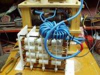
Obviously one would want to get rid the inverter of hard switching and unnecessary reactive power handling, which can be achieved using a dual resonant topology. A series resonant primary circuit would solve all the problems, but I thought I would require extremely high tank impedance in order to keep the current at a safe level. This would mean acquiring a high voltage, high reactive power tank capacitor as well as using many more turns on my primary which was not within my budget at time - so I acquired a large ferrite transformer to step the bridge voltage down, and used a 125nF CDE cap DRSSTC MMC as my resonant cap.
The results were very surprising - with 27:9 transformer ratio, the output was actually much less than with teh initial hard switching setup! I lowered the primary somewhat and got a slight increase in power output.
Primary current didn't even trip 40A limit during this run (with hard switched runs, it went over 80A peak!)
This is a very interesting result, because it means that if I reconfigured my H bridge to work as two parallel half bridges, I could implement series resonant topology without primary modifications! Why the coil draws relatively little power in this mode compared to DRSSTC's remains a question to ponder!
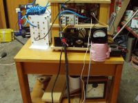
Some pics of the transformer and the cap:
More updates soon!
---old posts---
Hello all -
I haven't been around for a while - and I'm finally back with this project to share with you.
I'll start with some pictures, some questions, and update the thread over time. This project has started ages ago and I have actually forgotten a lot of it.
Current state of the coil - had it's first light, but died the other day due to unknown reasons. The mosfets died cold, just few tens of seconds into the run. I was way over confidentand didn't expect this to happen so early. Finally it was rebuilt with IGBT's and tested again.
Desired results: CW and interrupted runs from 3 phase supply with draw of up to 10kW with purpose of sowing general chaos. Lower power runs with half and full-wave rectified single phase.
Clues so far are:
1. my linear power supply. I used a 44VA 14V transformer, which I suspect may not be up to a task. I don't know how much can I trust a digital meter near the coil, but I measured the voltage to sag to about 11V when the coil is sparking - not looking good at all. I'm going to use a bigger transformer to see if the problem goes away. Or perhaps I should just use a 5A switching power supply? I originally intended that, and am not completely sure why I changed my mind for a linear supply now.
2. Sanity? I'm actually not sure whether I just pushed the TO247 mosfets too much. But I don't believe I can only get 40cm of CW spark from these! I'll post the part numbers of the mosfets when I find their bag tomorrow.
Here be the driver circuit schematic:

As you can see, I expressed minimalism the design, in attempt to minimize the number of problems that could occur.
I used a linear regulator with 2N3055 to provide 12V at several amps required by the circuitry and fans.
I decided the UCC37322 would make most reliable drivers and sufficient because of relatively low operating frequency. (<200kHz).
A current transformer samples the secondary base current, and is connected to pads CT1, CT2 in schematic. 12V zeners provide clamping, and schottky's prevent them from forward-conducting. Note that this arrangement provides symmetric drive to both UCC chips - I didn't use any additional buffers since CT signal is already clamped into nearly perfect squarewave.
The problem remains that this circuit is not self-starting - I solve this by introducing a TL494. It's purpose is to provide weak drive to the UCC's, and is easily overriden by CT signal when it gets strong. I can regulate the amount of signal by a potentiometer to +12V.
Now some construction pictures.
Starting point - CNC milled wooden frame:
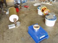
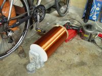
Winding the coil:
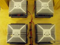
This H-bridge was created by one of my previous incarnations... most about it that I can't see right now, I've forgotten - don't ask me what mosfets are being used - I don't know! I suspect they are big and begin with FDH... Mosfets are pressed directly onto large CPU heatsinks with pieces of Al profile, with a thin layer of arctic silver thermal compound. I wanted to get out as much of allowable dissipation as humanly possible with TO247 devices.
EDIT: The devices are FDH44N50.

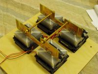
I used a single GDT made of RG174 cable per mosfet - for an really overkill gate drive.
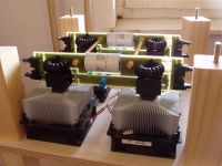
Whole thing starting to take shape:
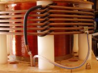
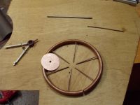
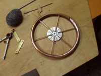
For primary supports, I used polypropylene rod cut in 6 pieces and tapped on a lathe. 6mm copper pipe was formed and zip-tied into shape.
I decided tomake the low voltage section as a rack I can get out of the coil easily - hence the additional piece of wood.
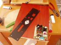
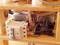
Inside of a high voltage section - it's not completed yet, but fine enough for now.
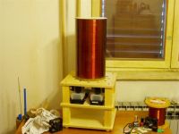
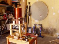
The whole thing nearing final shape:
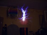
And yesterday, I finally got some sparks. I used a large three phase variac and feed to power the coil, producing some rather amazing CW sparks - due to 3 phase rectifier. I brought the power nearly to a full, nothing exploded, so I took some pics... Primary was still tapped on 6 turns, as I was cautious - still the CW sparks were at least like 40 cm long. I'd be grateful if someone could approximate input power by size of this spark - since I haven't tried to measure it yet.
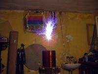
Due to obvious corona around the edge of secondary on this pic, I stopped the runs for the day - I didn't want to risk a breakout from an edge of a winding which would be very damaging. This had to be taken care of.
I built this corona ring which I mounted on the top of the secondary. I ran the coil again, only to blow the mosfets several tens of seconds into run. Heavily frustrated, I didn't take any more pics. I'm clueless about why this happened - since I've put so much work into this coil to make it buletproof. I haven't changed anything on the coil from the day before, apart from adding this ring and changing the breakout point from stainless steel to brass. Stainless had too low thermal conductivity and tended to melt and burn under spark.
So much for now -
Marko
Re: "Big Bad" the CW coil
Linas, Tue Aug 31 2010, 06:14PM
I like bridge , it looks good :)
also very cute GTD (white one ) (or whatever that is )
Linas, Tue Aug 31 2010, 06:14PM
I like bridge , it looks good :)
also very cute GTD (white one )
 (or whatever that is )
Re: "Big Bad" the CW coil
Steve Conner, Tue Aug 31 2010, 08:21PM
Hey Marko, looks great!
The power level is probably quite extreme. I've never seen a breakout point glow so bright that it causes lens flares. If you're running off 3 phase power, the DC bus voltage will be practically pure DC, so the sparks will be shorter for a given power throughput/level of MOSFET abuse. So maybe they just died of excessive power.
Also, isn't the FDH44N50 a 500V MOSFET? If you put 3-phase mains into a 6-pulse rectifier you get 560V DC out. So if you turned the variac "quite far up" you probably got quite close to the voltage rating. And your bridge layout has lots of stray inductance, because you had to put the MOSFETs far apart to make room for the heatsinks. So that's another possibility, maybe they avalanched themselves to death.
It doesn't matter whether you connect the variacs in star or delta, 100% on the dial will still give you 400V line to line and 560V out of your rectifier.
Finally, what about common-mode voltage getting into your CT? If there's a lot of RF voltage between your secondary base ground and your driver circuit ground, then it could couple through the CT's interwinding capacitance and give your gate driver chips a surprise.
One last thing, is your power supply RF proof? I once had a bench power supply that would increase its output voltage when it picked up RF, and destroy my circuit.
Steve Conner, Tue Aug 31 2010, 08:21PM
Hey Marko, looks great!

The power level is probably quite extreme. I've never seen a breakout point glow so bright that it causes lens flares. If you're running off 3 phase power, the DC bus voltage will be practically pure DC, so the sparks will be shorter for a given power throughput/level of MOSFET abuse. So maybe they just died of excessive power.
Also, isn't the FDH44N50 a 500V MOSFET? If you put 3-phase mains into a 6-pulse rectifier you get 560V DC out. So if you turned the variac "quite far up" you probably got quite close to the voltage rating. And your bridge layout has lots of stray inductance, because you had to put the MOSFETs far apart to make room for the heatsinks. So that's another possibility, maybe they avalanched themselves to death.
It doesn't matter whether you connect the variacs in star or delta, 100% on the dial will still give you 400V line to line and 560V out of your rectifier.
Finally, what about common-mode voltage getting into your CT? If there's a lot of RF voltage between your secondary base ground and your driver circuit ground, then it could couple through the CT's interwinding capacitance and give your gate driver chips a surprise.
One last thing, is your power supply RF proof? I once had a bench power supply that would increase its output voltage when it picked up RF, and destroy my circuit.
Re: "Big Bad" the CW coil
Marko, Wed Sept 01 2010, 01:25AM
Hi guys,
Linas: The cute toroidal coil is a feedback current transformer. Also it's not white, but pink!
Steve:
Bad news first. I did some DC load tests on the mosfets (I don't know why I didn't before) to see how they behave. I bolted one to same heatsink I used in the coil, and connected it straight to 5V rail of a large server power supply while holding the gate on. I was surprised to see the mosfet only drew about 24 amps in steady state - indicating a hot on-resistance of over 200 miliohms. Total dissipation was about 100W, and heatsink only got warm despite I used 2x less powerful fan than those in the coil.
Conclusion: satisfactory performance of heatsink, unsatisfactory performance of mosfets. After looking at thermal resistance characteristics in datasheet, projections of performance at high power appear grim. It's not unrealistic that mosfets will need to carry 30amps in operation in the coil - and this would already amount to 180W of just the conduction losses. Adding switching losses that may be in excess of 100W, it looks impossible to avoid junction temperature going nuclear with total thermal resistance of 0.5 k/W (junction to case + case to heatsink) - 300W of dissipation would result in 175C on the die even if I could keep the heatsink at constant 25C!
This made me wonder whether I pushed the limitations of what any discrete mosfet can do - their resistive nature makes them inherently unsuitable for large current switching.
I'm left with choice of either using a large number of parallel devices, or switching to IGBT's.
In comparison, while these mosfets rated at 44A would dissipate >180W just from conduction losses, and IGBT dropping 2V would dissipate only 60W - three-fold improvement.
I'm thinking of simply replacing the mosfets from the coil with some 30N60's - they are actually faster apart from turn-off delay time. Inductive hard switching may be worse on them, but I still think they'll be much more rugged than the mosfets.
Regarding other things: I didn't turn my variac too far up, I marked it and took special care about it. I never allowed more than 400V DC on the bridge, which is the rating of my DC block caps.
They are the same ground! I could never find a statisfactionary RF ground, and it's a real headache to me - I ground all my coild to neutral line. Once I used the water tap as a ground, only to realize it's getting very hot and could heat water boiling in it.
As far as I know, bad ground is only bad for my electronic devices - none of which are close to garage - if anyone has a theory about how it might cause mosfet death, please let me know!
I suppose it is, though I'll probably use an SMPS for next tests. Or should I be afraid of the SMPS for the same reason, and just take a bigger transformer? I could even get rid of regulator and run with unregulated supply.
Marko
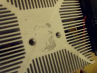
EDIT: Looks like I found what the problem was. After disassembling the bridge I realized one heatsink had hardly any thermal grease on it - this mosfet had to have really poot thermal contact! I'm surprised it lasted even this long. EIther the mosfet or the heatsink might have had poorer flatness, and the amount of grease I applied was just insufficient. I believed a thinner layer of grease would be beneficial - in the end I really just pushed this faith way too far.
I replaced the mosfets with IGBT's now anyway, going to try tomorrow. I doused them with as much grease I could and bolted them hard to the heatsinks.
Marko, Wed Sept 01 2010, 01:25AM
Hi guys,
Linas: The cute toroidal coil is a feedback current transformer. Also it's not white, but pink!
Steve:
Bad news first. I did some DC load tests on the mosfets (I don't know why I didn't before) to see how they behave. I bolted one to same heatsink I used in the coil, and connected it straight to 5V rail of a large server power supply while holding the gate on. I was surprised to see the mosfet only drew about 24 amps in steady state - indicating a hot on-resistance of over 200 miliohms. Total dissipation was about 100W, and heatsink only got warm despite I used 2x less powerful fan than those in the coil.
Conclusion: satisfactory performance of heatsink, unsatisfactory performance of mosfets. After looking at thermal resistance characteristics in datasheet, projections of performance at high power appear grim. It's not unrealistic that mosfets will need to carry 30amps in operation in the coil - and this would already amount to 180W of just the conduction losses. Adding switching losses that may be in excess of 100W, it looks impossible to avoid junction temperature going nuclear with total thermal resistance of 0.5 k/W (junction to case + case to heatsink) - 300W of dissipation would result in 175C on the die even if I could keep the heatsink at constant 25C!
This made me wonder whether I pushed the limitations of what any discrete mosfet can do - their resistive nature makes them inherently unsuitable for large current switching.
I'm left with choice of either using a large number of parallel devices, or switching to IGBT's.
In comparison, while these mosfets rated at 44A would dissipate >180W just from conduction losses, and IGBT dropping 2V would dissipate only 60W - three-fold improvement.
I'm thinking of simply replacing the mosfets from the coil with some 30N60's - they are actually faster apart from turn-off delay time. Inductive hard switching may be worse on them, but I still think they'll be much more rugged than the mosfets.
Regarding other things: I didn't turn my variac too far up, I marked it and took special care about it. I never allowed more than 400V DC on the bridge, which is the rating of my DC block caps.
Finally, what about common-mode voltage getting into your CT? If there's a lot of RF voltage between your secondary base ground and your driver circuit ground, then it could couple through the CT's interwinding capacitance and give your gate driver chips a surprise.
They are the same ground!
 I could never find a statisfactionary RF ground, and it's a real headache to me - I ground all my coild to neutral line. Once I used the water tap as a ground, only to realize it's getting very hot and could heat water boiling in it.
As far as I know, bad ground is only bad for my electronic devices - none of which are close to garage - if anyone has a theory about how it might cause mosfet death, please let me know!
One last thing, is your power supply RF proof? I once had a bench power supply that would increase its output voltage when it picked up RF, and destroy my circuit.
I suppose it is, though I'll probably use an SMPS for next tests. Or should I be afraid of the SMPS for the same reason, and just take a bigger transformer? I could even get rid of regulator and run with unregulated supply.
Marko
EDIT: Looks like I found what the problem was. After disassembling the bridge I realized one heatsink had hardly any thermal grease on it - this mosfet had to have really poot thermal contact! I'm surprised it lasted even this long. EIther the mosfet or the heatsink might have had poorer flatness, and the amount of grease I applied was just insufficient. I believed a thinner layer of grease would be beneficial - in the end I really just pushed this faith way too far.
I replaced the mosfets with IGBT's now anyway, going to try tomorrow. I doused them with as much grease I could and bolted them hard to the heatsinks.


Re: "Big Bad" the CW coil
Marko, Fri Sept 03 2010, 03:08PM
Hi guys,
After decision to replace the mosfets with igbt's, I ran the coil again on lower power levels, but this time with much better preparation. I put an amp meter onto one phase and slowly increased the power, leaving the coil at one power setting for few minutes to see how it behaves. I cranked the variac to about 50V - and was startled to see that the coil already draws nearly 10amps per phase just to produce a puny 10cm CW spark! Any my primary was already tapped at the last rurn. I increased the voltage a bit more and left the coil like that. After a few minutes, I noticed strong burning smell from the coil follower by smoke from the bridge section. I could witness the quite fat audio cable I used for primary connection melting and sliding out of it's insulation.
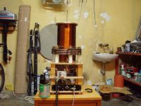
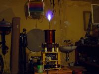
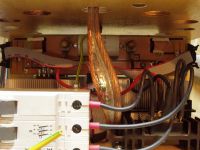
After replacing the damaged cable with battery cable, I ran for a while longer. I kept my nose high to notice any burning smells from the coil. And indeed after several minutes they did appear - but this time not from the cable, but from a zip tie at the end of my primary! As I stopped the run, it just fell off.
This wouldn't be unusual, if the primary wasn't only barely warm after the run - nowhere close enough to melt the strip! Also, it appears like heatink only occured in a very localized spot - which was not a spot in contact with the primary!
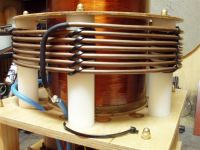
The missing tie wasn't a big deal,and I continued the run for some more, but watching closely - as soon as the smell appeared again, I shot off - now I could clearly see what was happening - on a zip tie just after the first one - yet it leaves me completely puzzled for now. I'm suspecting the black plastic maybe somehow conductive for HFHV and perhaps much more conductive when melted,starting a chain reaction which ultimately blows holes in the plastic.
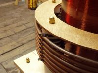
I'll try some white zipties to see whether they're immune to this problem.
Marko
Marko, Fri Sept 03 2010, 03:08PM
Hi guys,
After decision to replace the mosfets with igbt's, I ran the coil again on lower power levels, but this time with much better preparation. I put an amp meter onto one phase and slowly increased the power, leaving the coil at one power setting for few minutes to see how it behaves. I cranked the variac to about 50V - and was startled to see that the coil already draws nearly 10amps per phase just to produce a puny 10cm CW spark! Any my primary was already tapped at the last rurn. I increased the voltage a bit more and left the coil like that. After a few minutes, I noticed strong burning smell from the coil follower by smoke from the bridge section. I could witness the quite fat audio cable I used for primary connection melting and sliding out of it's insulation.


After replacing the damaged cable with battery cable, I ran for a while longer. I kept my nose high to notice any burning smells from the coil. And indeed after several minutes they did appear - but this time not from the cable, but from a zip tie at the end of my primary! As I stopped the run, it just fell off.
This wouldn't be unusual, if the primary wasn't only barely warm after the run - nowhere close enough to melt the strip! Also, it appears like heatink only occured in a very localized spot - which was not a spot in contact with the primary!

The missing tie wasn't a big deal,and I continued the run for some more, but watching closely - as soon as the smell appeared again, I shot off - now I could clearly see what was happening - on a zip tie just after the first one - yet it leaves me completely puzzled for now. I'm suspecting the black plastic maybe somehow conductive for HFHV and perhaps much more conductive when melted,starting a chain reaction which ultimately blows holes in the plastic.

I'll try some white zipties to see whether they're immune to this problem.
Marko
Re: "Big Bad" the CW coil
Luca, Fri Sept 03 2010, 05:56PM
Hi Marko,
maybe it's just dielectric loss of the plastic of the ties, which at high level of electric field can heat up and eventually melt the plastic itself...
Anyway, it's impressive...
Regards,
Luca
Luca, Fri Sept 03 2010, 05:56PM
Hi Marko,
maybe it's just dielectric loss of the plastic of the ties, which at high level of electric field can heat up and eventually melt the plastic itself...
Anyway, it's impressive...
Regards,
Luca
Re: "Big Bad" the CW coil
Marko, Fri Sept 03 2010, 10:48PM
Hi Luca
While I was running the coil again, the wooden ring on the top of my primary arced and caught fire. The secondary is mostly undamaged, mostly thanking pure luck. It turns out that wood is far too conductive to use in the place where I did, and brass screws made it even worse. It looks like electric field between primary was strong enough to cause invisible streamers, but which were still hot enough to melt the plastic zipties in their path. Above the first ziptie which is closest to the wood, a carbonization spot appeared. Another black spot few cm eated away the wood until it ran away into fierce fire and arced to the secondary.
I'll look into replacing the ring and bolts completely with plastic, although the primary seems quite stable even without any.
Marko
Re: "Big Bad" the CW coil
..., Sat Sept 04 2010, 03:03AM
A very nice coil!
It reminds me of my CW coil, I got ~6" out of it at 3kw DC input, so getting ~15" with upwards of 10kw sounds about right.
I found that using a piece of tungsten (I use the electrode out of a large xenon lamp) that was loosely connected to a piece of copper gave a reliable topload. The W would get glowing white hot, but the poor thermal contact to the copper prevented it from melting, and the W could handle the high temperatures.
I hope you can sort out the overheating issues, are you sure its not jut the primary getting hot due to eddie/i^2r losses? You could always run some water through it Those fdh44n50's are awesome mosfets, the die is the size of the entire mounting plate!
..., Sat Sept 04 2010, 03:03AM
A very nice coil!
It reminds me of my CW coil, I got ~6" out of it at 3kw DC input, so getting ~15" with upwards of 10kw sounds about right.
I found that using a piece of tungsten (I use the electrode out of a large xenon lamp) that was loosely connected to a piece of copper gave a reliable topload. The W would get glowing white hot, but the poor thermal contact to the copper prevented it from melting, and the W could handle the high temperatures.
I hope you can sort out the overheating issues, are you sure its not jut the primary getting hot due to eddie/i^2r losses? You could always run some water through it
 Those fdh44n50's are awesome mosfets, the die is the size of the entire mounting plate!
Re: "Big Bad" the CW coil
Steve Conner, Sat Sept 04 2010, 10:29AM
Glad to hear you've had no more silicon deaths!
You mentioned that you got heavy current draw even at low voltages. This is quite normal, Richie and I have seen it too. As you keep increasing the voltage, the current will level out.
The reason is that the spark clamps the top voltage to an almost constant value. As you increase the power, the plasma gets bigger, but the voltage doesn't really go up much. The resonator is a 1/4 wave transformer, so the constant voltage characteristic transforms to a constant current at the base.
Wood and brass screws? Time to replace those and sow some more general chaos for us, plz.

Re: "Big Bad" the CW coil
Marko, Sat Sept 04 2010, 04:26PM
Hi peter -
Meh, I hoped to acheive at least like 20inch CW sparks without going over 10kW :O Looks like I'm really underrating the amount of power CW sparks can eat.
I dislike the breakout points made of metals with poor thermal conductivity, because they glow so bright that they're uncomfortable to watch. I found brass to be by far best electrode material - copper has higher thermal conductivity but is oxidized in the air very fast. I've ran my brass breakout point for probably half a hour now and it's still sharp! I have to see what higher power levels will do to it, though.
Regarding the primary heating - no, it's just getting warm by now, at low power levels. And I also don't expect the primary current to increase significantly with increase in voltage. It was a wise decision to use a copper tube for the primary - it dissipates heat excellently with some air blown on it from beneath, which was not true for the audio cable with rather thick low-melting-point insulation.
Regarding mosfets - these were the largest ones I could come by easily. I cracked a dead one open, and the die is indeed so big that it barely fits in a package - I presume that it's probably the maximum of silicon one can place into a TO247 package. Still they don't seem to have all that great Rds ON, as they get hotter it seems to approach like 200miliohms! I might be passing up to like 40A through the mosfets. This would lead to 320W of dissipaton just from conduction alone! This dissipation is rather unmanageable for the package and just it's internal thermal resistance.
In comparison an IGBT dropping 2V would only dissipate 80W from conduction of the same current - a 4 fold improvement. Also, the 30N60's I have seem to have their forward voltage drop decrease with increase in temperature - to like 1.5V typ at 100C!
Use of igbt's over mosfets is certainly going to result in increased switching losses, though. Looking at the datasheet, just summing the turn on and off energies makes a grim prognosis. But I believe the losses in a sstc will actually be much less due to zero voltage switching. The igbt's also swithc the current at significantly less than it's peak value - they basically only switch the magnetizing current of the primary.
For now, the devices seemed rather cold after the runs - much colder than what mosfets felt after 50W DC load tests.
Still, I want to find a way to closely monitor the die temperature. I was considering to implant an SMT thermistor into the igbt - just underneath the collector leg, after perhaps drilling a small hole in the plastic to bury the NTC. I would solder the NTC down to the copper and using a floating supply (a battery) with a regulator and current meter to monitor it's resistance. This would provide me a great deal of knowledge about how much torture are the power devices taking in the operation.
I have some questions for you, Peter, since you seem to have a lot of experience with power devices - I was wondering what are the most powerful devices I could find in a TO247 package, for use in this coil. I would prefer either fast igbt's, or mosfets with really low Rds ON in SUPER TO247 package. I know there are such devices that have dies so large that they can't even put a hole on the to247 package. I've also seen 'elongated' ixys packages without holes which improve the dissipation even further.
I'd appreciate any ideas and possible means of acquiring some of such devices without too much pain.
Steve: yes, I've noticed that phenomenon long time ago. When secondary has little spark load it has very high Q and just tends to suck a lot of power from the primary circuit. I didn't expect it to draw over 10A so early though - my breaker and variac are both rated 10A - this was something like maximum I ever wanted to draw from the variac. Still I'm apparently going to increase the breaker to 16A and just pretend it doesn't matte rto the variac. It's so huge that I don't think it will bother it much anyway. I could lower my primary a bit down as well...
Marko
Marko, Sat Sept 04 2010, 04:26PM
... wrote ...
A very nice coil!
It reminds me of my CW coil, I got ~6" out of it at 3kw DC input, so getting ~15" with upwards of 10kw sounds about right.
I found that using a piece of tungsten (I use the electrode out of a large xenon lamp) that was loosely connected to a piece of copper gave a reliable topload. The W would get glowing white hot, but the poor thermal contact to the copper prevented it from melting, and the W could handle the high temperatures.
I hope you can sort out the overheating issues, are you sure its not jut the primary getting hot due to eddie/i^2r losses? You could always run some water through it Those fdh44n50's are awesome mosfets, the die is the size of the entire mounting plate!
A very nice coil!
It reminds me of my CW coil, I got ~6" out of it at 3kw DC input, so getting ~15" with upwards of 10kw sounds about right.
I found that using a piece of tungsten (I use the electrode out of a large xenon lamp) that was loosely connected to a piece of copper gave a reliable topload. The W would get glowing white hot, but the poor thermal contact to the copper prevented it from melting, and the W could handle the high temperatures.
I hope you can sort out the overheating issues, are you sure its not jut the primary getting hot due to eddie/i^2r losses? You could always run some water through it
 Those fdh44n50's are awesome mosfets, the die is the size of the entire mounting plate!
 Hi peter -
Meh, I hoped to acheive at least like 20inch CW sparks without going over 10kW :O Looks like I'm really underrating the amount of power CW sparks can eat.
I dislike the breakout points made of metals with poor thermal conductivity, because they glow so bright that they're uncomfortable to watch. I found brass to be by far best electrode material - copper has higher thermal conductivity but is oxidized in the air very fast. I've ran my brass breakout point for probably half a hour now and it's still sharp! I have to see what higher power levels will do to it, though.
Regarding the primary heating - no, it's just getting warm by now, at low power levels. And I also don't expect the primary current to increase significantly with increase in voltage. It was a wise decision to use a copper tube for the primary - it dissipates heat excellently with some air blown on it from beneath, which was not true for the audio cable with rather thick low-melting-point insulation.
Regarding mosfets - these were the largest ones I could come by easily. I cracked a dead one open, and the die is indeed so big that it barely fits in a package - I presume that it's probably the maximum of silicon one can place into a TO247 package. Still they don't seem to have all that great Rds ON, as they get hotter it seems to approach like 200miliohms! I might be passing up to like 40A through the mosfets. This would lead to 320W of dissipaton just from conduction alone! This dissipation is rather unmanageable for the package and just it's internal thermal resistance.
In comparison an IGBT dropping 2V would only dissipate 80W from conduction of the same current - a 4 fold improvement. Also, the 30N60's I have seem to have their forward voltage drop decrease with increase in temperature - to like 1.5V typ at 100C!
Use of igbt's over mosfets is certainly going to result in increased switching losses, though. Looking at the datasheet, just summing the turn on and off energies makes a grim prognosis. But I believe the losses in a sstc will actually be much less due to zero voltage switching. The igbt's also swithc the current at significantly less than it's peak value - they basically only switch the magnetizing current of the primary.
For now, the devices seemed rather cold after the runs - much colder than what mosfets felt after 50W DC load tests.
Still, I want to find a way to closely monitor the die temperature. I was considering to implant an SMT thermistor into the igbt - just underneath the collector leg, after perhaps drilling a small hole in the plastic to bury the NTC. I would solder the NTC down to the copper and using a floating supply (a battery) with a regulator and current meter to monitor it's resistance. This would provide me a great deal of knowledge about how much torture are the power devices taking in the operation.
I have some questions for you, Peter, since you seem to have a lot of experience with power devices - I was wondering what are the most powerful devices I could find in a TO247 package, for use in this coil. I would prefer either fast igbt's, or mosfets with really low Rds ON in SUPER TO247 package. I know there are such devices that have dies so large that they can't even put a hole on the to247 package. I've also seen 'elongated' ixys packages without holes which improve the dissipation even further.
I'd appreciate any ideas and possible means of acquiring some of such devices without too much pain.
Steve: yes, I've noticed that phenomenon long time ago. When secondary has little spark load it has very high Q and just tends to suck a lot of power from the primary circuit. I didn't expect it to draw over 10A so early though - my breaker and variac are both rated 10A - this was something like maximum I ever wanted to draw from the variac. Still I'm apparently going to increase the breaker to 16A and just pretend it doesn't matte rto the variac. It's so huge that I don't think it will bother it much anyway. I could lower my primary a bit down as well...
Marko
Re: "Big Bad" the CW coil
..., Sat Sept 04 2010, 06:01PM
The die in the ixfx55n50 is about as big as you can get period (at least for a mosfet, the bipolars come in the puck package now), you can get slightly better thermal contact by going to something in a brick package, but usually the benefit from a brick type package is better electrical contacts (as you don't have those tiny leads to deal with) which is something you aren't really having problems with. The solution is to parallel more of them together, the IGBT crowd does this extensively (inside the large brick modules there are a number of normal to-247 sized dies soldered to the same heat spreader), but it is trickier due to the positive temp coefficient associated with MOSFETS.
There is the super-20347 package you noted, but all this gives is a large heat spreader, so as long as you have good thermal contact between your mosfet and the heatsink, it won't help you much. You might want to confirm that you are in fact getting a good thermal bond, it is very possible to have a 50C+ temp drop from a mosfet to heatsink if you screw up the bond. However with the relatively small heat sinks you have I think a layer of artic silver won't be hurting you too much.
I think that at the power levels you are running for this coil, the IGBT will really win out in the end, at 200KHz they do become quite attractive. The good ones are pricy, but something like a IXGK60N60C2D1 should kick the mosfets where it hurts.
Re: "Big Bad" the CW coil
Marko, Sat Sept 04 2010, 07:37PM
I realize that for greater power levels, the only sane solution is likely going to be usage of bricks or paralleling devices myself. I'm still optimistic on this one though, and especially with igbt's. I have some large bricks around, but they are just incompatibile with this project - they's basically require complete rebuild of the coil.
I measured the frequency the coil resonates at with small spark, and it's 145kHz - which is likely going to get even lower, perhaps as low as 100kHz with full spark load!
Looking at the ixys igbt's from your post, they at first seemed to suffer higher saturation voltage than 30N60's, but examining the graphs showed otherwise.
I'd love to put some of those puppies into this project - they also seem to come in isoplus package which can come handy for lower power projects.
In short, *I really want them!* As usual digikey has them out-of-stock, and I only seem to find diodeless igbt's on ebay.
Still I always preffered uninsulated devices, because they have only like half J-C resistance of insulated ones. Despite my heatsinks look small, I believe my design thermally is better than any single giant freudian heatsink with ISOTOP devices on it.
I'm definitely considering implanting some NTC chips into the IGBT's as well - this way I'll not only have a safety measure, but I also think I'll learn a lot about all things that affect temperature of the devices - what helps, and what doesn't (increasing gate drive voltage, frequency, thickness of thermal paste layer, fan speeds...)
Marko
Re: "Big Bad" the CW coil
Kizmo, Sun Sept 05 2010, 09:02AM
CW coils
I personally like these because there is so much metal melting power packed in short plasma flame :)
Way more interesting than interrupted coils.. turn up the variac and see lights dimming
Got one with IRFP460 H-bridge

About 300V heavily filtered DC to bridge and 7 turn primary. Resonates at 300kHz. Secondary and primary wiring were almost smoking after that 20s run at ~4kW
EDIT:
Incomplete irfp460 bridge

Kizmo, Sun Sept 05 2010, 09:02AM
CW coils

I personally like these because there is so much metal melting power packed in short plasma flame :)
Way more interesting than interrupted coils.. turn up the variac and see lights dimming

Got one with IRFP460 H-bridge

About 300V heavily filtered DC to bridge and 7 turn primary. Resonates at 300kHz. Secondary and primary wiring were almost smoking after that 20s run at ~4kW
EDIT:
Incomplete irfp460 bridge

Re: "Big Bad" the CW coil
Marko, Sun Sept 05 2010, 07:03PM
Hi kizmo, nice to have you in the club!
Any more pics and details of your coil? I'd love to see a thread about it.
Insulated wire for the primary and PVC tube forms for secondary won't make it for long in CW operation. I built my own fiberglass tube to use for a secondary form, and copper tubing was necessary for the primary coil. Having some air blow around the base of your secondary and over the primary is of great help too -
my idea was to enclose the upper level of my coil in plexi so that all the air blown through the ehatsinks is also blown over the secondary base. This would probably cause some pressure increase and decrease the efficiency of fans, and I still haven't come to getting neither the primary nor seondary so hot actually!
Your bridge design is curious - I could never find a source of sil-pad sheet suitable for this purpose, and CPU heatsinks were cheap and I thought thermal resistance would be the lowest with direct contact to the heatsink anyway.
Marko
Re: "Big Bad" the CW coil
GeordieBoy, Tue Sept 07 2010, 02:45PM
Ooooh, CW SSTCs! Me likes!
Nice work Marko. It looks good. For increasing the power level i'd make the move to either larger die MOSFETs or parallel up a couple of something more modern than IRFP460's for more current. I found that IGBT's don't fair so well in prolonged CW duty unless they are the latest generation ones with heavily controlled current tailing.
You can get away with quite slow IGBTs in a DRSSTC where the operating frequency is quite low, and the devices can turn off softly as the current goes through zero. The small duty ratio of DRSSTC operation also massively helps keeping average switching losses under control!
In a CW SSTC with link coupled primary there's always quite a lot of inductive current flow from the inverter ("magnetising current") which means that the inverter won't switch at zero current. Even if it switches in phase with the resonator base current it will still have to interrupt at least a few amps of free-wheeling inductive current from the primary winding itself. MOSFETs love inductive loads because it minimises their turn-on losses and causes soft-recovery of the free-wheel diodes. IGBT's don't like it as much because interrupting the relatively large magnetising current causes current tailing and comparatively high turn-off losses.
Kizmo, Nice heat spreaders. Are you going to mount several MOSFETs on each one connected in parallel? It's nice to see someone paying a lot of attention to the thermal management side of the layout. Just remember to keep the devices as close together as you can to minimise stray inductance too. Particularly in the MOSFET, free-wheel diode and supply capacitor loop. This is where stray inductance is most damaging.
Marko, The "sil-pad sheet" is called Warth sheet here in UK. Made by a company called Warth Industries I think? You can also get ceramic material too that has good thermal properties and electrical insulation.

-Richie,
GeordieBoy, Tue Sept 07 2010, 02:45PM
Ooooh, CW SSTCs! Me likes!
Nice work Marko. It looks good. For increasing the power level i'd make the move to either larger die MOSFETs or parallel up a couple of something more modern than IRFP460's for more current. I found that IGBT's don't fair so well in prolonged CW duty unless they are the latest generation ones with heavily controlled current tailing.
You can get away with quite slow IGBTs in a DRSSTC where the operating frequency is quite low, and the devices can turn off softly as the current goes through zero. The small duty ratio of DRSSTC operation also massively helps keeping average switching losses under control!
In a CW SSTC with link coupled primary there's always quite a lot of inductive current flow from the inverter ("magnetising current") which means that the inverter won't switch at zero current. Even if it switches in phase with the resonator base current it will still have to interrupt at least a few amps of free-wheeling inductive current from the primary winding itself. MOSFETs love inductive loads because it minimises their turn-on losses and causes soft-recovery of the free-wheel diodes. IGBT's don't like it as much because interrupting the relatively large magnetising current causes current tailing and comparatively high turn-off losses.
Kizmo, Nice heat spreaders. Are you going to mount several MOSFETs on each one connected in parallel? It's nice to see someone paying a lot of attention to the thermal management side of the layout. Just remember to keep the devices as close together as you can to minimise stray inductance too. Particularly in the MOSFET, free-wheel diode and supply capacitor loop. This is where stray inductance is most damaging.
Marko, The "sil-pad sheet" is called Warth sheet here in UK. Made by a company called Warth Industries I think? You can also get ceramic material too that has good thermal properties and electrical insulation.

-Richie,
Re: "Big Bad" the CW coil
Marko, Tue Sept 07 2010, 05:02PM
Hi Richie,
Yes, I'm aware the IGBT's are going to suffer higher switching losses than mosfets, but I still believe they are going to beat them by far in conduction losses. I'm on college again so this project is suspended for a while.
The main reason I can't put more devices in parallel is lack of space on my heatsinks - I could probably fit two devices if I didn't drill those holes, but still I'd like to parallel at least like 4 or 6 devices to be sure, and cost of such a setup would be prohibitive.
Other problem with mosfets is that there just doesn't seem to be mosfets with significantly bigger die - 55N50's, and that's about it.
The IGBT's I'm using are HGTG30N60's - according to datasheets they actually seem to be faster than those big mosfets, especially when one considers fall time which is critical because of turning off large current...
IGBT's :
Mosfets:
Despite all this, I still want to remain careful, as these igbt's are hard to get and I don't want to blow them - I'll up the power in steps and measure the temperature of the devices during run.
One other thing I was thinking about, was to use series resonant primary circuit - like of a DRSSTC, but much higher impedance, with a primary of many turns and several nF of doorknob caps for the cap. This would yield two advantages:
- Good zero current switching on the igbt's,
- Possibility to lower the primary significantly to decrease the probability of flashover to it.
The biggest hurdle though is building the primary coil of required high inductance in a practical volume - due to very large currents involved, simple windings of insulated wire would pretty surely just melt, while copper pipe in required amount would be both expensive and very problematic to mount in small enough volume. (I may need several tens of turns!).
Marko
Marko, Tue Sept 07 2010, 05:02PM
Hi Richie,
Yes, I'm aware the IGBT's are going to suffer higher switching losses than mosfets, but I still believe they are going to beat them by far in conduction losses. I'm on college again so this project is suspended for a while.
The main reason I can't put more devices in parallel is lack of space on my heatsinks - I could probably fit two devices if I didn't drill those holes, but still I'd like to parallel at least like 4 or 6 devices to be sure, and cost of such a setup would be prohibitive.
Other problem with mosfets is that there just doesn't seem to be mosfets with significantly bigger die - 55N50's, and that's about it.
The IGBT's I'm using are HGTG30N60's - according to datasheets they actually seem to be faster than those big mosfets, especially when one considers fall time which is critical because of turning off large current...
IGBT's :

Mosfets:

Despite all this, I still want to remain careful, as these igbt's are hard to get and I don't want to blow them - I'll up the power in steps and measure the temperature of the devices during run.
One other thing I was thinking about, was to use series resonant primary circuit - like of a DRSSTC, but much higher impedance, with a primary of many turns and several nF of doorknob caps for the cap. This would yield two advantages:
- Good zero current switching on the igbt's,
- Possibility to lower the primary significantly to decrease the probability of flashover to it.
The biggest hurdle though is building the primary coil of required high inductance in a practical volume - due to very large currents involved, simple windings of insulated wire would pretty surely just melt, while copper pipe in required amount would be both expensive and very problematic to mount in small enough volume. (I may need several tens of turns!).
Marko
Re: "Big Bad" the CW coil
ScotchTapeLord, Tue Sept 07 2010, 06:42PM
CW with a resonant capacitor... Are you going to let the current ultimately be limited by the ohmic resistance? That's a lot of heat and some serious voltage across your resonant capacitors...
I had an idea to drive a sstc with this topology: which drives the primary at resonance but without resonant voltage rise.
But on the thread I started, people said that it wouldn't improve things much.
Perhaps it would make a difference with the power levels you are using, though.
ScotchTapeLord, Tue Sept 07 2010, 06:42PM
CW with a resonant capacitor... Are you going to let the current ultimately be limited by the ohmic resistance? That's a lot of heat and some serious voltage across your resonant capacitors...
I had an idea to drive a sstc with this topology:
 which drives the primary at resonance but without resonant voltage rise.
But on the thread I started, people said that it wouldn't improve things much.
Perhaps it would make a difference with the power levels you are using, though.
Re: "Big Bad" the CW coil
Marko, Tue Sept 07 2010, 07:25PM
Nah, the current is ultimately going to be limited by loading by the secondary. Though in order to keep the current within the safe area, a much higher impedance tank circuit would be required than in a normal DRSSTC.
I don't know how would LSR topology work on a SSTC, I've never hears of such a proposal.
Another possibility would be to use LCLR (another commonly used in induction heaters) topology, although I'm not sure how that would work.
Marko, Tue Sept 07 2010, 07:25PM
ScotchTapeLord wrote ...
CW with a resonant capacitor... Are you going to let the current ultimately be limited by the ohmic resistance? That's a lot of heat and some serious voltage across your resonant capacitors...
CW with a resonant capacitor... Are you going to let the current ultimately be limited by the ohmic resistance? That's a lot of heat and some serious voltage across your resonant capacitors...
Nah, the current is ultimately going to be limited by loading by the secondary. Though in order to keep the current within the safe area, a much higher impedance tank circuit would be required than in a normal DRSSTC.
I had an idea to drive a sstc with this topology: which drives the primary at resonance but without resonant voltage rise.
But on the thread I started, people said that it wouldn't improve things much.
I don't know how would LSR topology work on a SSTC, I've never hears of such a proposal.
Another possibility would be to use LCLR (another commonly used in induction heaters) topology, although I'm not sure how that would work.
Re: "Big Bad" the CW coil
teravolt, Wed Sept 08 2010, 04:58AM
hi Marko, maby a larger primary with more turns and higher coupling say .5 would help. aslo water cooled fets. Steve Ward uses this aproch in his QCW coil.


have you thought of using minibricks?
That is a tough project with the heating and power diapation but very cool. The spark looks like a class-E type spark
teravolt, Wed Sept 08 2010, 04:58AM
hi Marko, maby a larger primary with more turns and higher coupling say .5 would help. aslo water cooled fets. Steve Ward uses this aproch in his QCW coil.


have you thought of using minibricks?
That is a tough project with the heating and power diapation but very cool. The spark looks like a class-E type spark
Re: "Big Bad" the CW coil
Marko, Wed Sept 08 2010, 12:06PM
I'm a bit frustrated to realize that I'm too short on primary turns - I'm not going to be able to run on full available voltage - the coil just draws way too much current. I thought I have an overkill primary and that I'm going to settle for 3-4 turns, while in the end 6 proves not to be enough.
Copper pipe is not cheap so I'm unsure what to do regarding it.
Regarding steve's primary - his coil is still a pulsed one, not a completely CW coil like this - I would need much more primary turns than he has, and I just won't be able to fit that much copper pipe around the base of the coil. If I could find larger gauge litz wire it would probably work, but am not sure how to mount it.
Watercooling? Sorry, but I'm really not sure how to pull that off now - it would just be way over the budget and require rebuild of the whole coil.
And since I'm already exceeding the capabilities of my mains supply, it probably doesn't make much sense anyway.
If I wanted to push the CW to the end, I'd probably do something like a 50kW generator forthe supply, watercooled CM600 bricks, and series feed topology with 30kHz resonator... but it's not time for that yet.
Actually, no - apart being expensive and hard to find, they also have nearly twice as high internal thermal resistance compared to plain uninsulated TO247 devices. Hence I decided for them and four separate heatsinks and try to make TO247 devices give their max.
Mine or steve's project? :P
Cheers,
Marko
Marko, Wed Sept 08 2010, 12:06PM
teravolt wrote ...
hi Marko, maby a larger primary with more turns and higher coupling say .5 would help. aslo water cooled fets. Steve Ward uses this aproch in his QCW coil.


Hi teravolt - larger primary, definitely yes. More coupling - no, I already had a fire on this coil and am actually thinking to lower the primary. hi Marko, maby a larger primary with more turns and higher coupling say .5 would help. aslo water cooled fets. Steve Ward uses this aproch in his QCW coil.


I'm a bit frustrated to realize that I'm too short on primary turns - I'm not going to be able to run on full available voltage - the coil just draws way too much current. I thought I have an overkill primary and that I'm going to settle for 3-4 turns, while in the end 6 proves not to be enough.
Copper pipe is not cheap so I'm unsure what to do regarding it.
Regarding steve's primary - his coil is still a pulsed one, not a completely CW coil like this - I would need much more primary turns than he has, and I just won't be able to fit that much copper pipe around the base of the coil. If I could find larger gauge litz wire it would probably work, but am not sure how to mount it.
Watercooling? Sorry, but I'm really not sure how to pull that off now - it would just be way over the budget and require rebuild of the whole coil.
And since I'm already exceeding the capabilities of my mains supply, it probably doesn't make much sense anyway.
If I wanted to push the CW to the end, I'd probably do something like a 50kW generator forthe supply, watercooled CM600 bricks, and series feed topology with 30kHz resonator... but it's not time for that yet.
teravolt wrote ...
have you thought of using minibricks?
have you thought of using minibricks?
Actually, no - apart being expensive and hard to find, they also have nearly twice as high internal thermal resistance compared to plain uninsulated TO247 devices. Hence I decided for them and four separate heatsinks and try to make TO247 devices give their max.
teravolt wrote ...
That is a tough project with the heating and power diapation but very cool. The spark looks like a class-E type spark
That is a tough project with the heating and power diapation but very cool. The spark looks like a class-E type spark
Mine or steve's project? :P
Cheers,
Marko
Re: "Big Bad" the CW coil
vasil, Wed Sept 08 2010, 07:27PM
Why don't use copper or aluminium sheets/flashing for the primary coil? I remember that Jimmy Hynes used this idea for his DRSSTC. It is compact and allow more turns and a good coupling.
LINK
vasil, Wed Sept 08 2010, 07:27PM
Why don't use copper or aluminium sheets/flashing for the primary coil? I remember that Jimmy Hynes used this idea for his DRSSTC. It is compact and allow more turns and a good coupling.
LINK
Re: "Big Bad" the CW coil
Marko, Wed Sept 08 2010, 07:50PM
Hi vasil,
the idea is not bad, though in order to achieve required number of turns, I'd need to use thin copper foil tape would as densely as possible - and I'm afraid this may not dissipate heat too well. If I could sorce some copper foil tape someday, I could try a coil of it under my copper tube primary, with everything in series.
Marko
Marko, Wed Sept 08 2010, 07:50PM
vasil wrote ...
Why don't use copper or aluminium sheets/flashing for the primary coil? I remember that Jimmy Hynes used this idea for his DRSSTC. It is compact and allow more turns and a good coupling.
LINK
Why don't use copper or aluminium sheets/flashing for the primary coil? I remember that Jimmy Hynes used this idea for his DRSSTC. It is compact and allow more turns and a good coupling.
LINK
Hi vasil,
the idea is not bad, though in order to achieve required number of turns, I'd need to use thin copper foil tape would as densely as possible - and I'm afraid this may not dissipate heat too well. If I could sorce some copper foil tape someday, I could try a coil of it under my copper tube primary, with everything in series.
Marko
Re: "Big Bad" the CW coil
teravolt, Thu Sept 09 2010, 04:39AM
Mine or steve's project? :P
Cheers,
Marko
[/quote1284004071]
I think that your coil is more difficult because of the amount of power you have to manage. Certainly Steve's is more complex.
It seems to me that your primary is choked up quite a bit on the secondary have you tried pushing it to the bottom yet. In your picture of the primary the enamel seems to pealing off the secondary and it seems to me that having your primary so high is cosing the lower part of the secondary to heat. how do you feel about a tapered primary to the bottom?
I have also noticed that you have no MMC wich I believe is by design. If you had a MMC you may get the higher impedance that you want with the added benifit of a high voltage rise accross your primary. What kind of caps would you choose for the power you are dealing with since you are melting 10awg wire.
What is your secondary F res.
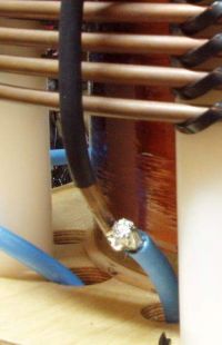
teravolt, Thu Sept 09 2010, 04:39AM
teravolt wrote ...
That is a tough project with the heating and power dissipation but very cool. The spark looks like a class-E type spark
That is a tough project with the heating and power dissipation but very cool. The spark looks like a class-E type spark
Mine or steve's project? :P
Cheers,
Marko
[/quote1284004071]
I think that your coil is more difficult because of the amount of power you have to manage. Certainly Steve's is more complex.
It seems to me that your primary is choked up quite a bit on the secondary have you tried pushing it to the bottom yet. In your picture of the primary the enamel seems to pealing off the secondary and it seems to me that having your primary so high is cosing the lower part of the secondary to heat. how do you feel about a tapered primary to the bottom?
I have also noticed that you have no MMC wich I believe is by design. If you had a MMC you may get the higher impedance that you want with the added benifit of a high voltage rise accross your primary. What kind of caps would you choose for the power you are dealing with since you are melting 10awg wire.
What is your secondary F res.

Re: "Big Bad" the CW coil
Marko, Thu Sept 09 2010, 03:39PM
Hi teravolt,
Yes, the primary is choked up as high as possible since high coupling is of benefit for this type of coil. The main reason why I want to lower is is to hog a bit less power at lower voltages. I'd be much better if I had just a few more turns.
You are wrong about the secondary heating, though - it really is just ugly varnish, and I haven't seen the secondary get more than lukewarm. I used the same resin from which the form was cast (boat polyester resin) diluted with styrene to coat the coil, although the resulting mixture was still too thick and didn't spread too well.
I'm afraid that lowering the primary will actually cause the bottom of the secondary to heat up more.
Though I don't understand what you mean with "tapered primary to the bottom"?
I'm not sure what you mean by this. I have a DC blocking cap which is a sort of ''MMC'' of four parallel caps, but a series resonant MMC is a no-go in this case. With my current primary it would just turn the coil into DRSSTC. I obviously want to run CW, not with primary current going for hundreds of amps.
The coil was measured to resonate at 145kHz with small spark load.
Marko
Marko, Thu Sept 09 2010, 03:39PM
Hi teravolt,
It seems to me that your primary is choked up quite a bit on the secondary have you tried pushing it to the bottom yet. In your picture of the primary the enamel seems to pealing off the secondary and it seems to me that having your primary so high is cosing the lower part of the secondary to heat. how do you feel about a tapered primary to the bottom?
Yes, the primary is choked up as high as possible since high coupling is of benefit for this type of coil. The main reason why I want to lower is is to hog a bit less power at lower voltages. I'd be much better if I had just a few more turns.
You are wrong about the secondary heating, though - it really is just ugly varnish, and I haven't seen the secondary get more than lukewarm. I used the same resin from which the form was cast (boat polyester resin) diluted with styrene to coat the coil, although the resulting mixture was still too thick and didn't spread too well.
I'm afraid that lowering the primary will actually cause the bottom of the secondary to heat up more.
Though I don't understand what you mean with "tapered primary to the bottom"?
I have also noticed that you have no MMC wich I believe is by design. If you had a MMC you may get the higher impedance that you want with the added benifit of a high voltage rise accross your primary. What kind of caps would you choose for the power you are dealing with since you are melting 10awg wire.
I'm not sure what you mean by this. I have a DC blocking cap which is a sort of ''MMC'' of four parallel caps, but a series resonant MMC is a no-go in this case. With my current primary it would just turn the coil into DRSSTC. I obviously want to run CW, not with primary current going for hundreds of amps.
The coil was measured to resonate at 145kHz with small spark load.
Marko
Re: "Big Bad" the CW coil
teravolt, Fri Sept 10 2010, 03:48AM
Yes, the primary is choked up as high as possible since high coupling is of benefit for this type of coil. The main reason why I want to lower is is to hog a bit less power at lower voltages. I'd be much better if I had just a few more turns.
Though I don't understand what you mean with "tapered primary to the bottom"?
what I ment is a primary where the windings are set up in a tapered angle like my picture that starts at the bottom of the secondary
I'm not sure what you mean by this. I have a DC blocking cap which is a sort of ''MMC'' of four parallel caps, but a series resonant MMC is a no-go in this case. With my current primary it would just turn the coil into DRSSTC. I obviously want to run CW, not with primary current going for hundreds of amps.
I asume that you are basicly using the XLprimary and XCmmc say 10 ohm to controle the current. how about a parallel
resonant cap that way the primary circulating current will be high between L and C that way your bridge won't have to work so hard because a parallel tank has high Z at resonance. If you had that set up you could use a parallel L-R network in series with your primary and your bridge like a VTTC to very power. Does that make sense? By the way how much peak current is flowwing in the primary turns?
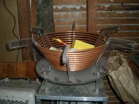
teravolt, Fri Sept 10 2010, 03:48AM
Yes, the primary is choked up as high as possible since high coupling is of benefit for this type of coil. The main reason why I want to lower is is to hog a bit less power at lower voltages. I'd be much better if I had just a few more turns.
Though I don't understand what you mean with "tapered primary to the bottom"?
what I ment is a primary where the windings are set up in a tapered angle like my picture that starts at the bottom of the secondary
I have also noticed that you have no MMC wich I believe is by design. If you had a MMC you may get the higher impedance that you want with the added benifit of a high voltage rise accross your primary. What kind of caps would you choose for the power you are dealing with since you are melting 10awg wire.
I'm not sure what you mean by this. I have a DC blocking cap which is a sort of ''MMC'' of four parallel caps, but a series resonant MMC is a no-go in this case. With my current primary it would just turn the coil into DRSSTC. I obviously want to run CW, not with primary current going for hundreds of amps.
I asume that you are basicly using the XLprimary and XCmmc say 10 ohm to controle the current. how about a parallel
resonant cap that way the primary circulating current will be high between L and C that way your bridge won't have to work so hard because a parallel tank has high Z at resonance. If you had that set up you could use a parallel L-R network in series with your primary and your bridge like a VTTC to very power. Does that make sense? By the way how much peak current is flowwing in the primary turns?

Re: "Big Bad" the CW coil
Marko, Sat Sept 11 2010, 01:12PM
A parallel LC circuit has high impedance at it's center frequency, but the inverter puts out square wave with high frequency components for which it would basically be a short. Driving a large capacitor by the inverter is never good at all.
If I added a series inductor to the bridge output, I would get LCLR. Richie B. told me once that such a topology would work for a sstc, but I had little luck with it in low power tests. It seems to take a while for the primary tank to ring up - hence I may benefit from my improved startup circuit.
I also don't have any knowledge on how would this circuit behave at these power levels, and whether I would get any soft switching benefits at all. I suspect the inductor may give me ZVS but I would hae large current to turn off.
Marko
Marko, Sat Sept 11 2010, 01:12PM
how about a parallel resonant cap that way the primary circulating current will be high between L and C that way your bridge won't have to work so hard because a parallel tank has high Z at resonance. If you had that set up you could use a parallel L-R network in series with your primary and your bridge like a VTTC to very power. Does that make sense? By the way how much peak current is flowwing in the primary turns?
A parallel LC circuit has high impedance at it's center frequency, but the inverter puts out square wave with high frequency components for which it would basically be a short. Driving a large capacitor by the inverter is never good at all.
If I added a series inductor to the bridge output, I would get LCLR. Richie B. told me once that such a topology would work for a sstc, but I had little luck with it in low power tests. It seems to take a while for the primary tank to ring up - hence I may benefit from my improved startup circuit.
I also don't have any knowledge on how would this circuit behave at these power levels, and whether I would get any soft switching benefits at all. I suspect the inductor may give me ZVS but I would hae large current to turn off.
Marko
Re: "Big Bad" the CW coil
Steve Ward, Tue Sept 14 2010, 06:28PM
Just as a comment:
I have run my QCW coil in true CW mode, but it was with either a 3nF or 10nF tank cap and i had to use a big 18" diameter primary with ~8-10 turns (i think). It resonated at 350khz or so, so its a fairly high tank impedance. The spark ultimately limits the primary current. The benefit is that you can achieve real ZCS this way, whereas an untuned primary never will (even with PLL tricks). This is quite a "big deal" in my opinion, given that switching losses are probably dominant (well certainly at 360khz they are). Since Marko doesnt happen to have a bank of Mica caps to handle such duty, its probably not an option.
Re: "Big Bad" the CW coil
Marko, Tue Sept 14 2010, 07:56PM
Hi Steve,
I actually have a handful of 3.3nF 10kV, 20kVar doorknob caps laying around. I wonder if a bank of them (say 20nF, since my frequency is about half of yours) would be suitable for the purpose?
Regarding the primary, I'm surprised that you got away with ''only'' 10 turns. My primary is about 12inches, and I could fit about 12 turns reasonably on the outside, and then perhaps another 5-6 on the inside of the PP studs (perhaps a re-use of my current primary coil?). I would need less than 60 microhenries with a 20 nF cap so I may even have some margin in there.
The cost of copper is a bit high, but I might invest in another 12 meters of pipe if it proves worthy to use such a topology. I may want to test it small scale first.
I'm too busy with my college now and not with too much time to dream about this until christmas. I heavily appreciate your experimental efforts, since I thought a much higher impedance would be required any I would most likely have to come to it by trial and error.
I want to do some experiments and measurements nevertheless, both on this coil and smaller scale. I'm too concerned with the cold deaths of mosfets in some of my smaller scale experiments, and that has to stop. I have many things to try, and what I want is to build a bullet-proof small scale system before progressing further.
Marko
Re: "Big Bad" the CW coil
Steve Ward, Thu Sept 23 2010, 06:31PM
Those caps sound OK, being rated at 20kVARs each they should be good for a few amps RMS each id guess, so with plenty of them in parallel, and not demanding extremely long run times, they ought to work.
Id also highly recommend some sort of phase compensating circuit, either PLL or this "prediktor" type thing to get better ZCS. The penalty for hard switching is pretty bad at these high frequencies, supposing you really want to maximize the capacity of your switches. Ive seen hard switched designs that run 300kHz at work, and they de-rate the IGBTs to maybe 20% of the DC rating to keep it running.
Re: "Big Bad" the CW coil
Marko, Thu Sept 23 2010, 09:32PM
Hi steve -
I'm curious, do you have any pics of your coil running true CW? And what power level would you estimate it to?
Marko
Marko, Thu Sept 23 2010, 09:32PM
Hi steve -
I'm curious, do you have any pics of your coil running true CW? And what power level would you estimate it to?
Marko
Re: "Big Bad" the CW coil
Marko, Sun Oct 16 2011, 12:27AM
Hi everyone,
After a long, long time I finally did some more runs on this onster, all successful with hgtg30N60 igbt's still in place.
I now installed an overcurrent protection circuit, replaced the troublesome primary former and filmed for whatever is going to come out of the coil.
From the action of the curent limiter I could now estimate the values of the primary current, and they are indeed batshit insane. For the run in the video I set it to over 60amps, while these igbt's are rated for only like 30amps at 100kHz. I put the faith into the fact that the devices are only switching a portion of this current, so perhaps less than 30A in "hard switching", as well as into shear ruggedness of these devices.

The coil stops in the video once the current limiter acts, I set it with a quite large time constant, so I can turn the variac down a bit when this occurs. Had the coil break out once from the side of it's toroid when it restarted, will need a bigger toroid soon!
Only one big problem remains - my fans seem to slow down when the coil is run (this can actually be heard in the video) apparently due to very close proximity to live heatsinks (yet I didn't see this happen with other models of fans). So I'm most likely going to have to shield or replace the fans, the first is a lot of work and the second is costly. But for short runs this seems ok and heatsinks are dead cold all the time.
I may try to run this until destruction just for the heck of it tomorrow... as it certainly looks like I'm not going to get much more power with this bridge in this topology. I measured the DC bus voltage and single phase current with moving coil meters - in this run I was up to about 300V and 16A; my brain hurts now because I'm unsure how to read this data, if those 16A were real RMS current per phase and power factor is close to unity this would mean over 14kW input which just can't be right... I also have a 10A breaker that didnt trip even with this overload.
Regarding the fate of this coil, I might definitely want to upgrade it to series resonant topology or something similar that won't put such extreme reactive power stress onto the bridge. Instead of buying prohibitive amounts of copper pipe I was thinking of using a bigass ferrite transformer, to step down the output from my bridge. With a core such as one of these:
The resonant cap still remains a problem though, for my current primary I'd need about 100nF cap with very high current rating. (BTW, those doorknobs I had turned out to be the useless type).
Still if I got a proper resonant cap I could even upgrade the coil into QCW one day.
Marko
PS. Can anyone point out to some usable capacitors on ebay? I'm kind of lost regarding what to look for. Would I have any use from those old mica/silver bricks?
At last I thought I can use a big geek cap MMC borrowed from the DRSSTC, although that's probably rather overkill.
PS^2 What about a bank of these caps?

Marko, Sun Oct 16 2011, 12:27AM
Hi everyone,
After a long, long time I finally did some more runs on this onster, all successful with hgtg30N60 igbt's still in place.
I now installed an overcurrent protection circuit, replaced the troublesome primary former and filmed for whatever is going to come out of the coil.
From the action of the curent limiter I could now estimate the values of the primary current, and they are indeed batshit insane. For the run in the video I set it to over 60amps, while these igbt's are rated for only like 30amps at 100kHz. I put the faith into the fact that the devices are only switching a portion of this current, so perhaps less than 30A in "hard switching", as well as into shear ruggedness of these devices.

The coil stops in the video once the current limiter acts, I set it with a quite large time constant, so I can turn the variac down a bit when this occurs. Had the coil break out once from the side of it's toroid when it restarted, will need a bigger toroid soon!
Only one big problem remains - my fans seem to slow down when the coil is run (this can actually be heard in the video) apparently due to very close proximity to live heatsinks (yet I didn't see this happen with other models of fans). So I'm most likely going to have to shield or replace the fans, the first is a lot of work and the second is costly. But for short runs this seems ok and heatsinks are dead cold all the time.
I may try to run this until destruction just for the heck of it tomorrow... as it certainly looks like I'm not going to get much more power with this bridge in this topology. I measured the DC bus voltage and single phase current with moving coil meters - in this run I was up to about 300V and 16A; my brain hurts now because I'm unsure how to read this data, if those 16A were real RMS current per phase and power factor is close to unity this would mean over 14kW input which just can't be right... I also have a 10A breaker that didnt trip even with this overload.
Regarding the fate of this coil, I might definitely want to upgrade it to series resonant topology or something similar that won't put such extreme reactive power stress onto the bridge. Instead of buying prohibitive amounts of copper pipe I was thinking of using a bigass ferrite transformer, to step down the output from my bridge. With a core such as one of these:

The resonant cap still remains a problem though, for my current primary I'd need about 100nF cap with very high current rating. (BTW, those doorknobs I had turned out to be the useless type).
Still if I got a proper resonant cap I could even upgrade the coil into QCW one day.
Marko
PS. Can anyone point out to some usable capacitors on ebay? I'm kind of lost regarding what to look for. Would I have any use from those old mica/silver bricks?
At last I thought I can use a big geek cap MMC borrowed from the DRSSTC, although that's probably rather overkill.
PS^2 What about a bank of these caps?

Re: "Big Bad" the CW coil
Marko, Wed Nov 23 2011, 02:47AM
OMG updatez! ;)
Marko, Wed Nov 23 2011, 02:47AM
OMG updatez! ;)
Re: "Big Bad" the CW coil
Goodchild, Wed Nov 23 2011, 09:08PM
HAHA ok that was great, I love how the fans speed back up again after the sparks turn off. You must be pulling a ton of current from the wall!!
Goodchild, Wed Nov 23 2011, 09:08PM
HAHA ok that was great, I love how the fans speed back up again after the sparks turn off. You must be pulling a ton of current from the wall!!
Re: "Big Bad" the CW coil
Marko, Sun Nov 27 2011, 02:34AM
Hey guys,
well, neither my caps nor the fans have arrived yet, but I did some work on fixing my variac startup circuit to finally stop it from tripping breakers when being plugged in... Fluorescent tube starter now adds the extra delay required. Should do some good CW spork when I finally get myupgrade parts.
Marko

Re: "Big Bad" the CW coil
tarakan2, Thu Mar 30 2017, 04:57AM
May I see the schematic for the H bridge driver, please.
Is it a good idea to use a single GDT driver transformer?
http://kaizerpowerelectronics.dk/wp-content/gallery/2009_08_27_-_kaizer_drsstc_i/kaizerdrsstc1bridge.gif
tarakan2, Thu Mar 30 2017, 04:57AM
May I see the schematic for the H bridge driver, please.
Is it a good idea to use a single GDT driver transformer?
http://kaizerpowerelectronics.dk/wp-content/gallery/2009_08_27_-_kaizer_drsstc_i/kaizerdrsstc1bridge.gif
Print this page