Woooohooo! (Boost converter success)
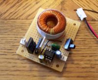
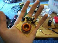
aahz, Sun Apr 02 2006, 01:14PMFinally got my 555 driven boost converter working.
Charges a single 450v 470uf capacitor to 450v from a 12v lead acid battery within three seconds. (I have 17 more for my bank, so charging time shouldn't be too bad.) Not sure of the max voltage, but it's definately well above 450v.
Anyway, if anyone wants specs, I'll post em later. Right now, pics!


Re: Woooohooo! (Boost converter success)
Kipmans, Sun Apr 02 2006, 01:39PM
Looks neat, but can you post some more info on the used parts and/or a circuit diagram?
Kipmans, Sun Apr 02 2006, 01:39PM
Looks neat, but can you post some more info on the used parts and/or a circuit diagram?
Re: Woooohooo! (Boost converter success)
aahz, Sun Apr 02 2006, 03:14PM
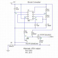
Here's the diagram. I've posted the IGBT and Diode part numbers next to their symbols.
'bout to see how it does for a long charge.

aahz, Sun Apr 02 2006, 03:14PM
Here's the diagram. I've posted the IGBT and Diode part numbers next to their symbols.
'bout to see how it does for a long charge.

Re: Woooohooo! (Boost converter success)
Dr. Shark, Sun Apr 02 2006, 05:16PM
Nice one! Now add a 5k resistor in series with the 1M, compare the voltage across that with a reference voltage and get it to switch off once it has reached a set voltage.
Dr. Shark, Sun Apr 02 2006, 05:16PM
Nice one! Now add a 5k resistor in series with the 1M, compare the voltage across that with a reference voltage and get it to switch off once it has reached a set voltage.
Re: Woooohooo! (Boost converter success)
HV Enthusiast, Sun Apr 02 2006, 05:59PM
Or you can have fun, close the loop, and make it regulate.
HV Enthusiast, Sun Apr 02 2006, 05:59PM
Or you can have fun, close the loop, and make it regulate.
Re: Woooohooo! (Boost converter success)
aahz, Sun Apr 02 2006, 06:41PM
One wierd thing that I've noticed, though.... the inductor whines at the frequency of the 555. It sounds like it might be arcing, but there's no visible evidence of that.... though I can't keep it on long, since it'll over-voltage the caps after a couple of seconds.
aahz, Sun Apr 02 2006, 06:41PM
One wierd thing that I've noticed, though.... the inductor whines at the frequency of the 555. It sounds like it might be arcing, but there's no visible evidence of that.... though I can't keep it on long, since it'll over-voltage the caps after a couple of seconds.
Re: Woooohooo! (Boost converter success)
Dr. Shark, Sun Apr 02 2006, 06:49PM
thats quite usual. I doubt it would be arcing, the varnish usually stands several 1000V.
Dr. Shark, Sun Apr 02 2006, 06:49PM
thats quite usual. I doubt it would be arcing, the varnish usually stands several 1000V.
Re: Woooohooo! (Boost converter success)
aahz, Sun Apr 02 2006, 06:50PM
So then, just vibration from the actual induction?
aahz, Sun Apr 02 2006, 06:50PM
So then, just vibration from the actual induction?
Re: Woooohooo! (Boost converter success)
rupidust, Sun Apr 02 2006, 08:24PM
Ah closure. Was wonder if my previous advice was thrown out the window. See, 97% duty is not needed to boost 12v to 450v. Appears the signal is 1.5kHZ at ~70% duty. 47 Joules / 3 seconds showes this to be a 15 Watt charger. Not bad after overcoming a few problems.
The noise is just the frequency of oscillation. Try running at 20kHZ and the whine will dim down to inaudibility. There are techniques to suppress the noise for lower frequencies.
1. Keep the inductor away from proximity with metal surfaces. The noise will just be amplified.
2. Wrap a layer or two of double sided clear scotch tape around the ferrite core. I use ferrite beads because the coilforming is faster and layers are easy to form.
3. Make shure the coil windings are tight. A thin coating of epoxy or CA glue helps.
As always, the frequency must match the inductor. The higher the frequency, the lower and possibly smaller the inductor.
Re: Woooohooo! (Boost converter success)
aahz, Sun Apr 02 2006, 09:23PM
Haha. You should see the graveyard of parts I have. I overlooked a connection the first time around on the pcb and completely melted an IGBT, burned up multiple 555's (Oh well, I only have about 30 more of those... ) a capacitor, a few resistors (still good, but charred), and a few other IGBT's that are damaged, but not completely destroyed.
Anyway, I've come to a good balance for my frequency. It's high enough to limit current enough so the IGBT doesn't heat up too badly, and it's low enough to get good output. I've tried playing with the duty cycle a bit, but only with minimal gains in output with seemingly large amounts of heat increase. I even tried a < 50% duty cycle (Placed a diode across r2 and increased r2's resistance) with no clear advantages.
As for the whine, I've just wrapped it in tape after soaking it in a little CA... I somehow made it louder. Not sure how that happened. Oh well, as long as it doesn't interfere with performance, I'm fine with a little whine.
And again, thanks for the help.
Re: Woooohooo! (Boost converter success)
rupidust, Sun Apr 02 2006, 11:54PM
Like the others said, next step is to integrate feedback. Actually trying to up the watts power should be next. Once you varify its at least 70% efficienty then its time to move one. You measure the current in series with the IGBT at ground level. Take that current and multiply it by the voltage of the inductor supply to get Watts. Compare usage watts to charging watts to rate performance.
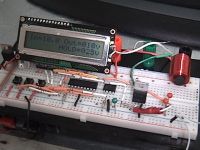
Here is a pic of an advanced booster operating at 30 Watts from 12v supply. This can charge caps or battery packs. Image is in battery charge mode. The difference is the voltage divider used to monitor the charge voltage: divide by 100 for caps and 10 for batteries. The heart of the booster is a PIC 16F819. Using 3 of the 5 analog to digital converting lines, I monitor the voltage of the battery supply, load voltage (cap or another battery), and current of the charger. The PIC also drives the LCD in 4-bit address mode. Boost signal is amplified by an 8 pin dual Mosfet driver, which relays the signal to an IGBT. To the left there are 3 buttons. One to decrease the HOLD/regulate voltage, one to increase this, and another to start/stop charging. Of course once the charge voltage reaches the HOLD voltage, the charger stops then begins regulation mode. If there are no bleeders across the cap bank, the charger stops for a long time. The heavier the bleeder, the more regulation pulses are sent to the cap to maintain charge level. There is always a bleeder because the feedback voltage divider across the cap is in essence a bleeder.
Link to Video of Cap mode http://geocities.com/rupidust1/booster-lcd1.wmv

More one the PIC. Ok, this is so far beyond beginner level but here goes anyway. The booster is running in an interrupt background, turning the IGBT on/off at programmed times and duty cycles. In the normal flow of code is everthing else. One A2D line voltage is compared with an A2D_level variable. When ever the A2D line voltate is >= the A2D_level variable, another variable is then toggled to stop the booster when the next interrupt service routine happends. The buttons are continuously monitored along with voltage. When a particular button is pressed, the code vectors to another sub routine to either, decrement the Hold voltage(A2D_level), increment it, or stop charging all together. For either increment or decrement, the LCD display of HOLD = XXXv is updated. Before the LCD is updated 3 math sub routines are used. First, multiply a 16bit value by another 16bit value resulting in a 32bit value: A2D_level * 20(mv) to create a calculated representation of load voltage. The second sub routine converts 16bit Hex values into a 5 digit BCD value Ten thousands, Thousands, Hundres, Tens, and Ones. The third sub routines converts decimal numbers into LCD ascii numbers by adding 0x30 to a number. Thanks be to internal PIC EEPROM, the last HOLD voltage is automatically remembered on powerup. Battery mode increments the HOLD voltage by 1 and Cap mode increments it by 10. Cap charge range is from 50v to 500v. If I need higher voltage, I just change the voltage divider ratio and modify the code.
rupidust, Sun Apr 02 2006, 11:54PM
Like the others said, next step is to integrate feedback. Actually trying to up the watts power should be next. Once you varify its at least 70% efficienty then its time to move one. You measure the current in series with the IGBT at ground level. Take that current and multiply it by the voltage of the inductor supply to get Watts. Compare usage watts to charging watts to rate performance.
Here is a pic of an advanced booster operating at 30 Watts from 12v supply. This can charge caps or battery packs. Image is in battery charge mode. The difference is the voltage divider used to monitor the charge voltage: divide by 100 for caps and 10 for batteries. The heart of the booster is a PIC 16F819. Using 3 of the 5 analog to digital converting lines, I monitor the voltage of the battery supply, load voltage (cap or another battery), and current of the charger. The PIC also drives the LCD in 4-bit address mode. Boost signal is amplified by an 8 pin dual Mosfet driver, which relays the signal to an IGBT. To the left there are 3 buttons. One to decrease the HOLD/regulate voltage, one to increase this, and another to start/stop charging. Of course once the charge voltage reaches the HOLD voltage, the charger stops then begins regulation mode. If there are no bleeders across the cap bank, the charger stops for a long time. The heavier the bleeder, the more regulation pulses are sent to the cap to maintain charge level. There is always a bleeder because the feedback voltage divider across the cap is in essence a bleeder.
Link to Video of Cap mode http://geocities.com/rupidust1/booster-lcd1.wmv

More one the PIC. Ok, this is so far beyond beginner level but here goes anyway. The booster is running in an interrupt background, turning the IGBT on/off at programmed times and duty cycles. In the normal flow of code is everthing else. One A2D line voltage is compared with an A2D_level variable. When ever the A2D line voltate is >= the A2D_level variable, another variable is then toggled to stop the booster when the next interrupt service routine happends. The buttons are continuously monitored along with voltage. When a particular button is pressed, the code vectors to another sub routine to either, decrement the Hold voltage(A2D_level), increment it, or stop charging all together. For either increment or decrement, the LCD display of HOLD = XXXv is updated. Before the LCD is updated 3 math sub routines are used. First, multiply a 16bit value by another 16bit value resulting in a 32bit value: A2D_level * 20(mv) to create a calculated representation of load voltage. The second sub routine converts 16bit Hex values into a 5 digit BCD value Ten thousands, Thousands, Hundres, Tens, and Ones. The third sub routines converts decimal numbers into LCD ascii numbers by adding 0x30 to a number. Thanks be to internal PIC EEPROM, the last HOLD voltage is automatically remembered on powerup. Battery mode increments the HOLD voltage by 1 and Cap mode increments it by 10. Cap charge range is from 50v to 500v. If I need higher voltage, I just change the voltage divider ratio and modify the code.
Re: Woooohooo! (Boost converter success)
Dr. Shark, Fri Apr 07 2006, 11:51AM
Aahz, inspired by your converter I decided to put one together to do some overvoltage stress testing on MMC capacitors I recently accquired. Shame was, it worked too well! By using a rather small inductor (output filter on the 5V line of a ATX PSU) of 100uH or so, I managed to overvolt a 600V IGBT in an instant. This was at 50% duty-cycle, discontinous mode of course. Just to let those nay-sayers know how much voltage these little things can pack!
Re: Woooohooo! (Boost converter success)
Steve Ward, Fri Apr 07 2006, 07:43PM
This is easily predictable with V=-L*di/dt. You have to be careful about the inductance path between IGBT/diode and output capacitor. Anyway, with 100uH, and switching say 10Apk in 100nS, your max V would be about 10kV. This is why you must either 1) keep a load on the converter at all times, or 2) use voltage feedback. There are many design considerations with converters... far too much to get into right now, but if you dont want them to blow up, you better read up on them more first .
.
Steve Ward, Fri Apr 07 2006, 07:43PM
Just to let those nay-sayers know how much voltage these little things can pack!
This is easily predictable with V=-L*di/dt. You have to be careful about the inductance path between IGBT/diode and output capacitor. Anyway, with 100uH, and switching say 10Apk in 100nS, your max V would be about 10kV. This is why you must either 1) keep a load on the converter at all times, or 2) use voltage feedback. There are many design considerations with converters... far too much to get into right now, but if you dont want them to blow up, you better read up on them more first
 .
.Re: Woooohooo! (Boost converter success)
IamSmooth, Wed Apr 26 2006, 09:54PM
Regarding your schematic for the Boost Converter, why is R10 (1M ohm) resistor needed?
Is it to provide a discharge path in case there is no load on the output?
Second question: by changing the value of the inductor the voltage output goes up; so, what are the limitations as to how large an inductor one can use for a set input voltage? Is it the amout of current you want delivered?
Re: Woooohooo! (Boost converter success)
Wilson, Thu Apr 27 2006, 02:14AM
I presume R10 is there as a bleeder resistor for any caps aahz might charge.
Using too large an inductor may limit your max output voltage, as di/dt (current rise time) won't be as high as with a smaller inductor.
Wilson, Thu Apr 27 2006, 02:14AM
I presume R10 is there as a bleeder resistor for any caps aahz might charge.
Using too large an inductor may limit your max output voltage, as di/dt (current rise time) won't be as high as with a smaller inductor.
Re: Woooohooo! (Boost converter success)
Steve Ward, Thu Apr 27 2006, 09:30PM
Thats not how it works. The di/dt is determined by the switch (not the inductor). So in fact, a larger inductor would give a bigger inductive kick assuming the same current (built up at the time of switching) and switching speed.
Steve Ward, Thu Apr 27 2006, 09:30PM
Using too large an inductor may limit your max output voltage, as di/dt (current rise time) won't be as high as with a smaller inductor.
Thats not how it works. The di/dt is determined by the switch (not the inductor). So in fact, a larger inductor would give a bigger inductive kick assuming the same current (built up at the time of switching) and switching speed.
Re: Woooohooo! (Boost converter success)
IamSmooth, Fri Apr 28 2006, 12:45AM
So, what is the difference in performance if one starts increasing the inductance? The voltage goes up as di/dt is fixed, but does the current go down? There has to be some trade-off if the output voltage continues to increase?
IamSmooth, Fri Apr 28 2006, 12:45AM
So, what is the difference in performance if one starts increasing the inductance? The voltage goes up as di/dt is fixed, but does the current go down? There has to be some trade-off if the output voltage continues to increase?
Re: Woooohooo! (Boost converter success)
Steve Ward, Fri Apr 28 2006, 07:21PM
You might be "missing the point" with boost converters. There are 2 basic operations going on in the conversion. 1) build up energy in the inductor, and 2) discharge energy into output storage device (capacitor). Then comes in the numerous factors that you must consider if you want to build the best converter given any constraints that you have. Basically, start with what output voltage and current that you want, and depending on the mode of operation (continuous vs. discontinuous) you can figure out the inductor current more or less. From here you have to juggle switching frequency and inductance. These 2 will be very closely related once you decide on the peak inductor current (and the change in current during the discharge period if running continuously). Because you must deliver some specific amount of energy per cycle, this determines the frequency you must operate at. Also, since the current can only build up at a specific rate (V=L*di/dt) this also puts constraints on L and freq. Anyway, im starting to ramble here, and the point is, you cant explain the whole converter design in a paragraph. If you are really curious, i suggest you search for "boost converter design" on google. This is how i learned what i know.
For you guys that are just charging capacitors and dont really care about getting high output current, you probably dont care as much about a proper design. Just keep in mind some way to protect the output voltage from going too high. A boost converter with no load (or regulation) is a very dangerous thing to itself. As i proved before, its easy to produce multi kV output from the inductor unless you have some capacitor to clamp this voltage as stored energy.
Steve Ward, Fri Apr 28 2006, 07:21PM
So, what is the difference in performance if one starts increasing the inductance? The voltage goes up as di/dt is fixed, but does the current go down? There has to be some trade-off if the output voltage continues to increase?
You might be "missing the point" with boost converters. There are 2 basic operations going on in the conversion. 1) build up energy in the inductor, and 2) discharge energy into output storage device (capacitor). Then comes in the numerous factors that you must consider if you want to build the best converter given any constraints that you have. Basically, start with what output voltage and current that you want, and depending on the mode of operation (continuous vs. discontinuous) you can figure out the inductor current more or less. From here you have to juggle switching frequency and inductance. These 2 will be very closely related once you decide on the peak inductor current (and the change in current during the discharge period if running continuously). Because you must deliver some specific amount of energy per cycle, this determines the frequency you must operate at. Also, since the current can only build up at a specific rate (V=L*di/dt) this also puts constraints on L and freq. Anyway, im starting to ramble here, and the point is, you cant explain the whole converter design in a paragraph. If you are really curious, i suggest you search for "boost converter design" on google. This is how i learned what i know.
For you guys that are just charging capacitors and dont really care about getting high output current, you probably dont care as much about a proper design. Just keep in mind some way to protect the output voltage from going too high. A boost converter with no load (or regulation) is a very dangerous thing to itself. As i proved before, its easy to produce multi kV output from the inductor unless you have some capacitor to clamp this voltage as stored energy.
Print this page