
Rogowski coil construction
aonomus, Mon Jan 26 2009, 05:30PMSo I've been doing some reading on various members rogowski coils that they've made and found a few PDFs which left me with a few questions... I'm trying to build a rogowski coil to measure current in my CG, and my future cap bank.
1. How many windings and of what gauge? They need to be evenly distributed and from what I've seen most people have used fairly fine stuff, but higher windings generally means larger output voltage range? Target
2. Active vs passive integrators, how hard is it to build one over the other since I'd like to have multiple-uses (mostly CG/pulse usage).
3.
 describes target inductance at about 200-300nH, is this a solid number, or can it vary?
Overall I've just seen formulae and pictures of construction, however I don't understand [multivariate] calculus so I get confused when trying to figure out the math behind it all. What I'm looking for is something, anything with some solid values to work from since I can't figure out the calculations :S. Sorry if it seems like I'm digging for answers but I've seen Rogowski coils pop up all over the place with no listed values...
Related links:


Re: Rogowski coil construction
Proud Mary, Mon Jan 26 2009, 05:38PM
Let us suppose that the output from the coil is a very fast, steep, transient - I wondered how you intended to record that.
Proud Mary, Mon Jan 26 2009, 05:38PM
Let us suppose that the output from the coil is a very fast, steep, transient - I wondered how you intended to record that.
Re: Rogowski coil construction
aonomus, Mon Jan 26 2009, 05:46PM
Either use a sound card oscilloscope (first guess), or worse case scenario, borrow a DSO from an acquaintance.
My discharges should be in the range of milliseconds. Sound cards can handle well into 15-20kHz which means a resolution down to 0.0x ms. I'd likely use extra isolation just in case* but I think the sound card scope should work for this purpose.
aonomus, Mon Jan 26 2009, 05:46PM
Harry wrote ...
Let us suppose that the output from the coil is a very fast, steep, transient - I wondered how you intended to record that.
Let us suppose that the output from the coil is a very fast, steep, transient - I wondered how you intended to record that.
Either use a sound card oscilloscope (first guess), or worse case scenario, borrow a DSO from an acquaintance.
My discharges should be in the range of milliseconds. Sound cards can handle well into 15-20kHz which means a resolution down to 0.0x ms. I'd likely use extra isolation just in case* but I think the sound card scope should work for this purpose.
Re: Rogowski coil construction
aonomus, Mon Jan 26 2009, 11:46PM
I could never really find the schematic for what TDU made... thanks Dalus.
As for the coil itself, its simply a function of winding it, and calibrating correct?
aonomus, Mon Jan 26 2009, 11:46PM
I could never really find the schematic for what TDU made... thanks Dalus.
As for the coil itself, its simply a function of winding it, and calibrating correct?
Re: Rogowski coil construction
Steve Conner, Tue Jan 27 2009, 12:03PM
If I remember right, the mutual inductance between a Rogowski coil and the conductor it encircles, is just the loop area of a turn, times the number of turns, times the permeability of free space.
You don't need to be Stephen Hawking to work out the calibration coefficient from that and the time constant of your integrator.
Re: Rogowski coil construction
aonomus, Tue Jan 27 2009, 12:12PM
Stephen Hawking can't move his hands so I suppose he'd have trouble building a rogowski coil -.-
Also I see the term (n x A x Uo) coming up in alot of the forumula ( ). Now things are starting to come together (I didn't even know what Uo was (google returned crap about ultima online).
aonomus, Tue Jan 27 2009, 12:12PM
Stephen Hawking can't move his hands so I suppose he'd have trouble building a rogowski coil -.-
Also I see the term (n x A x Uo) coming up in alot of the forumula (
 ). Now things are starting to come together (I didn't even know what Uo was (google returned crap about ultima online).
Re: Rogowski coil construction
Steve Conner, Tue Jan 27 2009, 03:21PM
Yes, it's too bad that keyboards don't come with Greek letters and subscripts. Try googling "mu nought" instead.
If I remember right, the sensitivity of a Rogowski coil with an integrator is:
(Vout/I) =(1/RC)*(n*A*u0)
and if using a passive "integrator" you should also choose RC such that the time constant is at least 10 times longer than the phenomenon you're trying to measure.
I used them to measure Tesla coil primary currents (over 5kA peak in my OLTC experiments) and I used a passive integrator with a break frequency (1/(2*pi*RC)) one-tenth of the coil's resonant frequency. There are details in the old forum archives somewhere.
Re: Rogowski coil construction
aonomus, Wed Jan 28 2009, 01:54AM
So today I bought 20 ft of RG6 coax and spent a little while stripping a little under 12" of sheath, braid, and foil to get to the dielectric (also put the BNC connector on the other end). Tomorrow when I get any free time, I'll wind the entire length with 30AWG magnet wire (leftover wire).
I also bought a metal case, small transformer, and some other bits, I'll have to find 1% resistors and pick decent opamps for the integrator (I'm going to go with active). Any recommended 'budget' opamps? I've looked at a few and they are all $10-20/per
One other question is whether or not I should ground the metal case or not, on one hand I have a AC transformer inside, but on the other hand I don't want to form any freaky ground loops with any equipment. Should the shield of the rogowski coil be grounded as well?
Re: Rogowski coil construction
rp181, Thu Jan 29 2009, 02:01AM
cool! now you don't need to double post =p
rp181, Thu Jan 29 2009, 02:01AM
cool! now you don't need to double post =p
Re: Rogowski coil construction
aonomus, Thu Jan 29 2009, 02:12AM
So I've constructed the coil and given it a whirl using my coilgun and it seems to work ok. I don't have a integrator for it, it is only the rogowski coil itself plugged into a scope. Some construction photos:
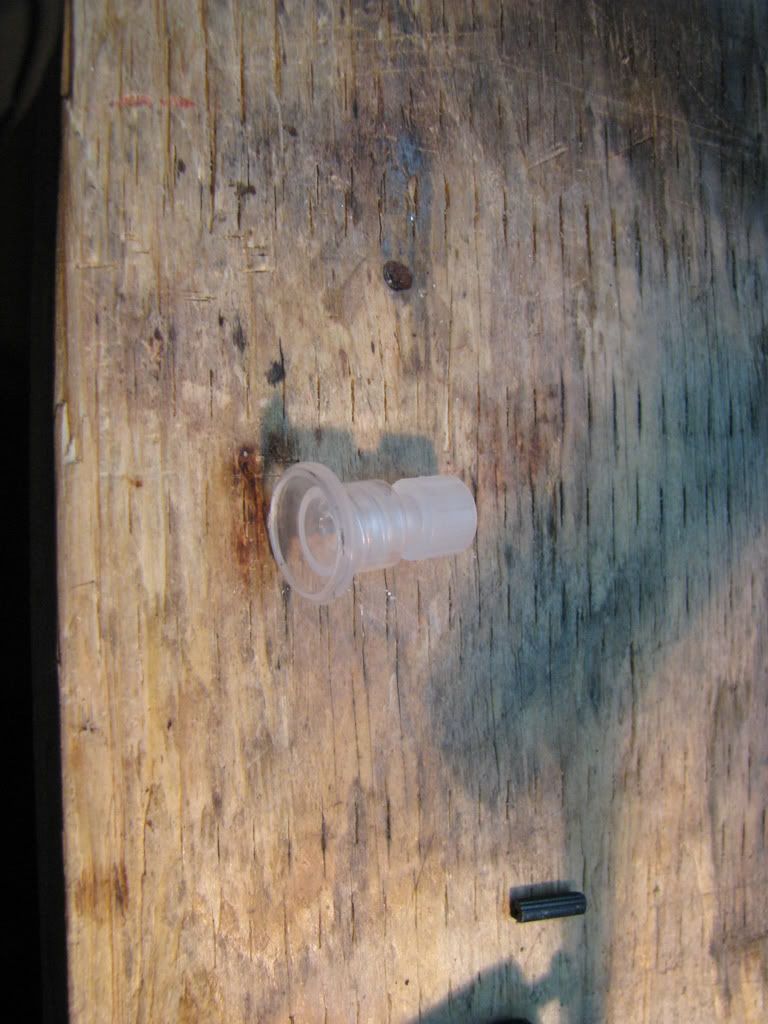
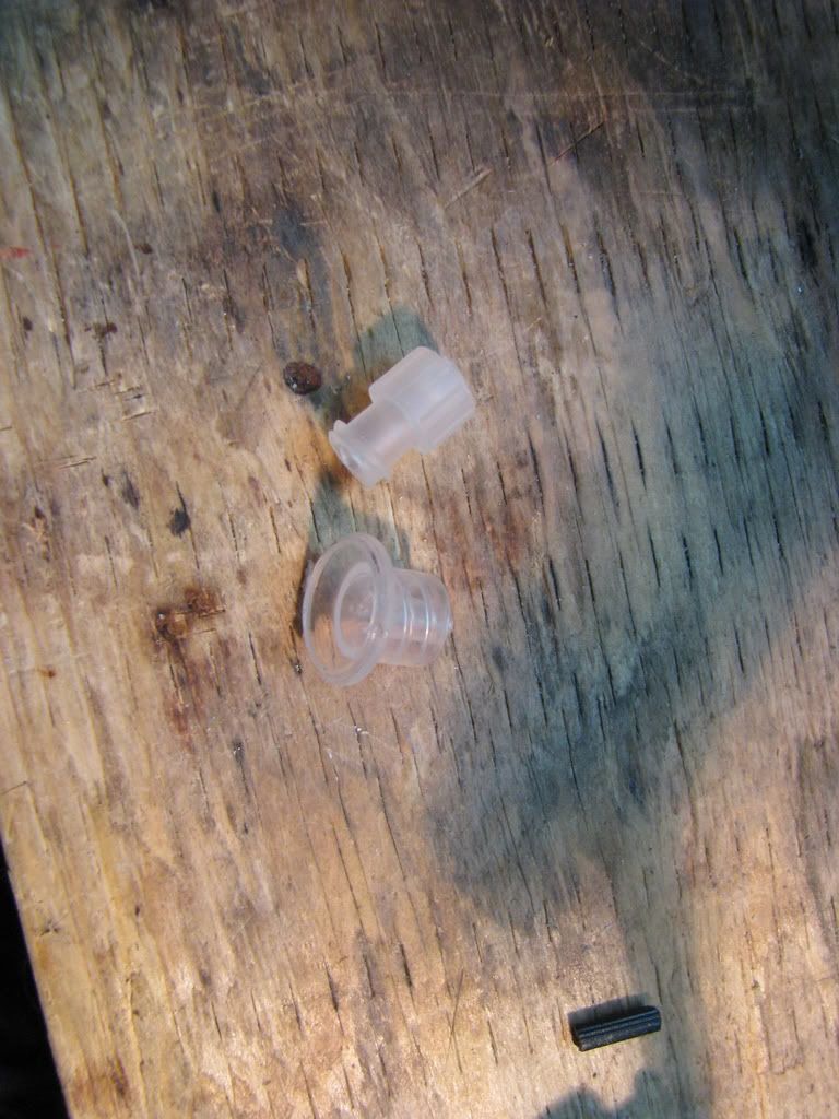
I used a luer lock fittings (from syringes and fluid handling stuff) for the connector
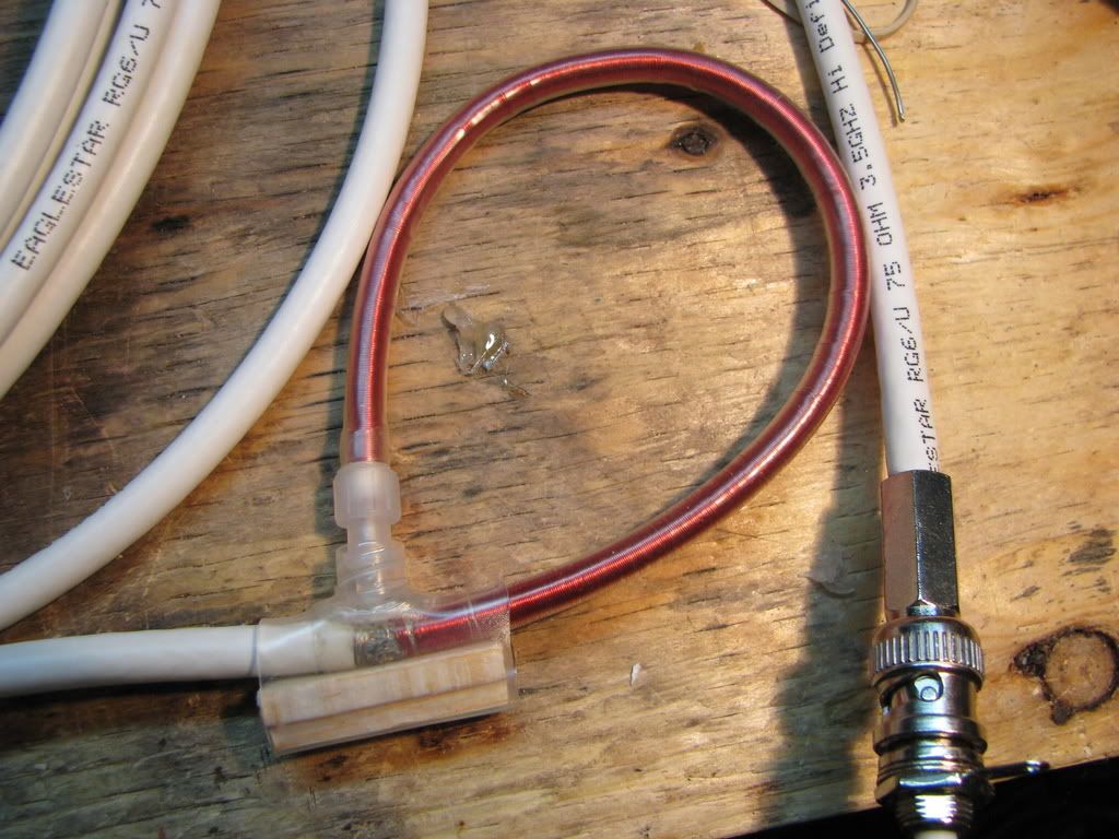
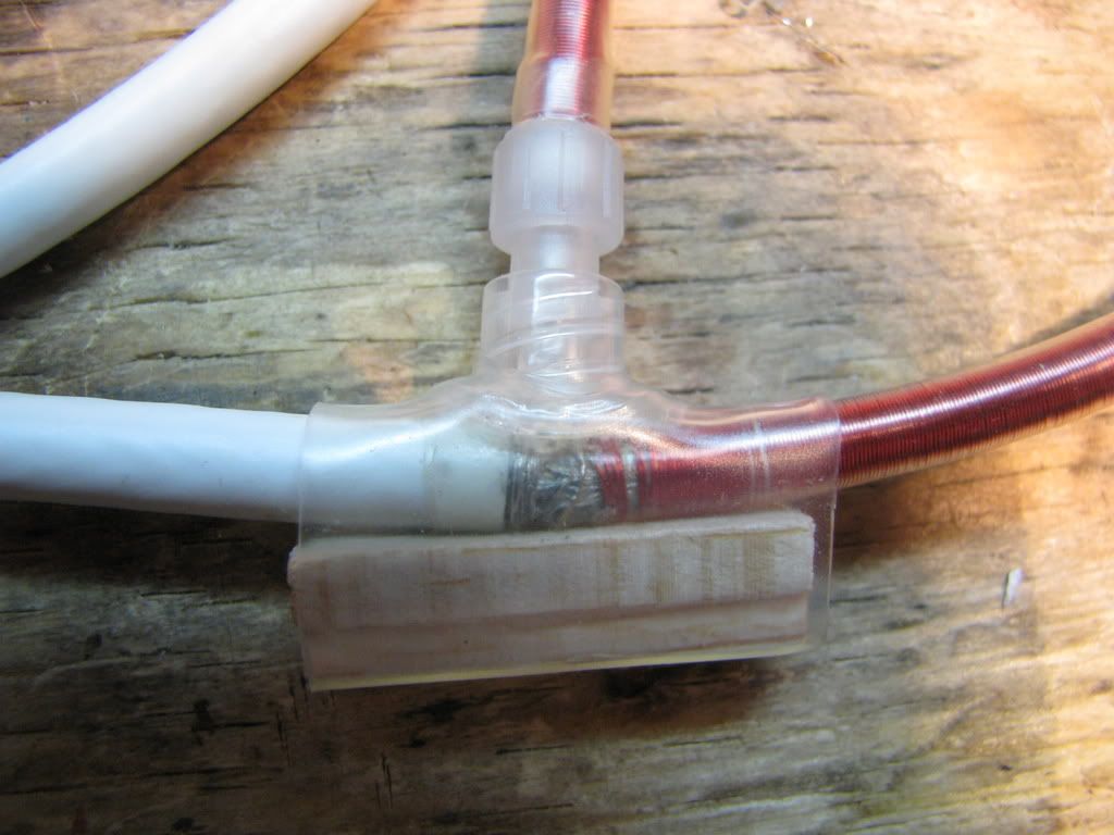
A closeup of the coil.
I used 20ft of RG6 with a twist-on BNC connector (no crimper), 30AWG magnet wire for the coil itself.
For my first test I used my biggest induction motor fan on 120VAC and got this:
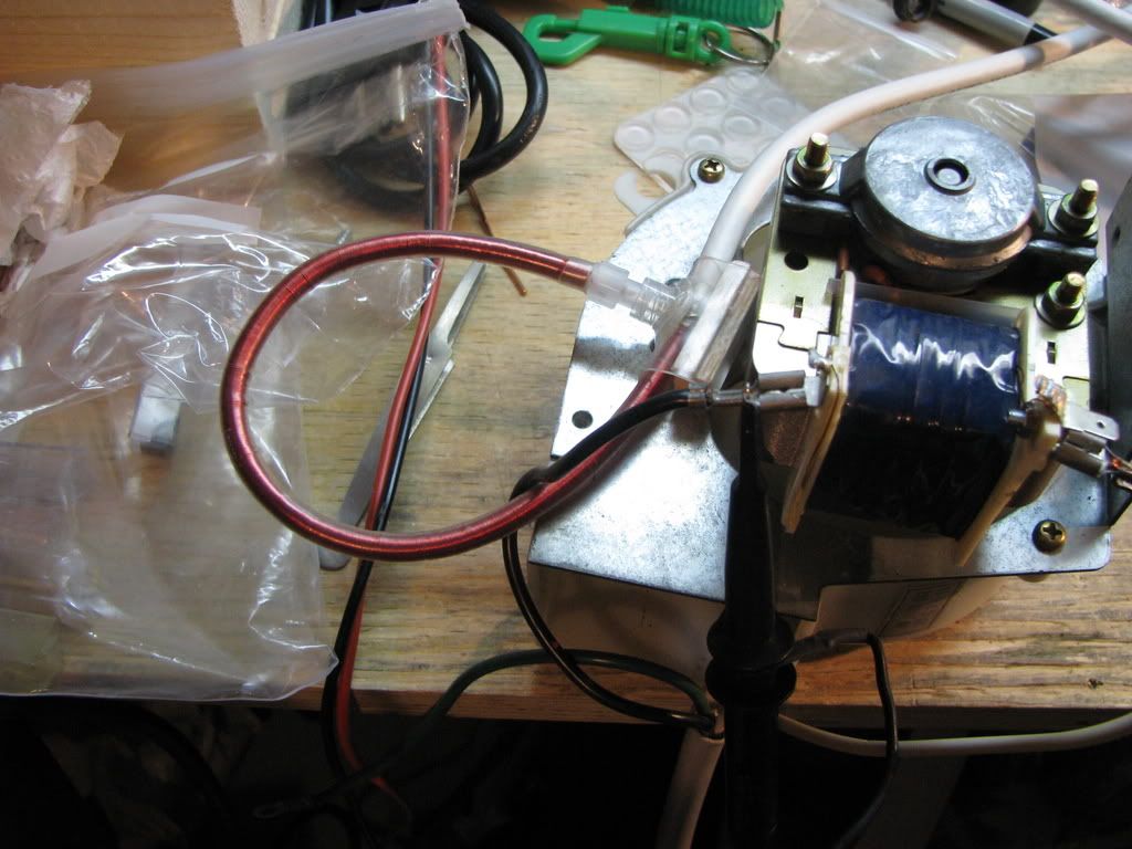
Test setup
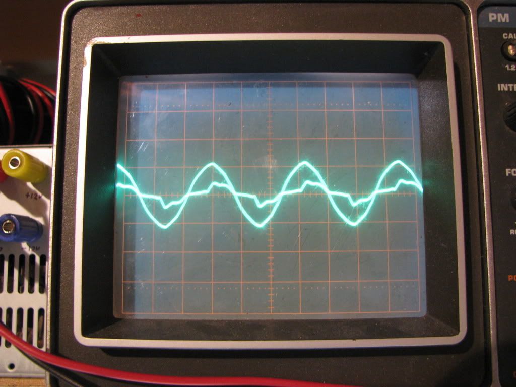
Sinewave: 120VAC
Choppy wave: Current
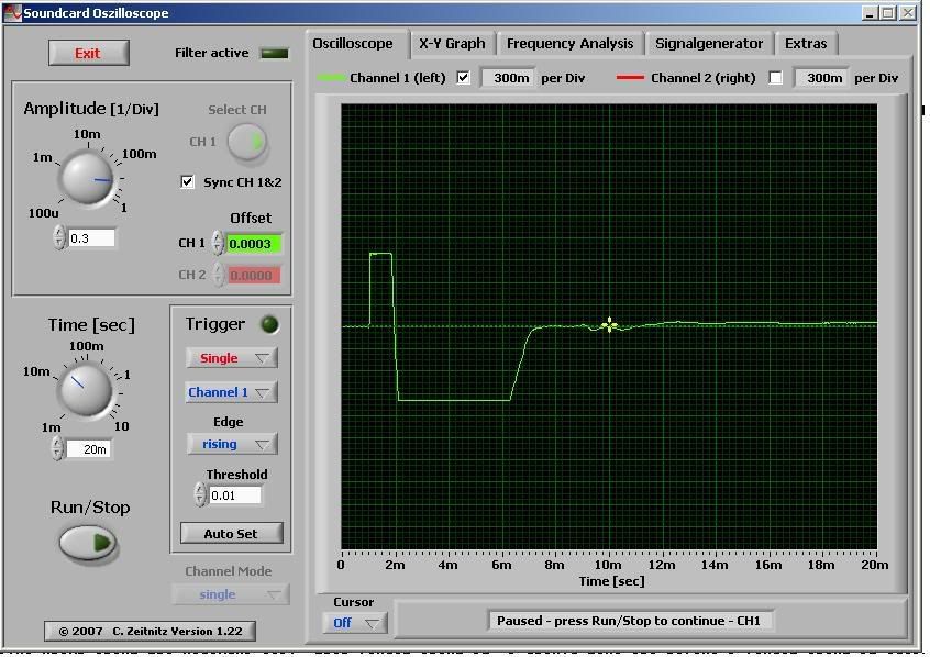
My second test was with my coilgun with different projectiles and voltages, and worked out pretty well. I captured the waveforms using my laptop's soundcard as a cheap DSO, however I maxed out the card and the waveforms got clipped at higher powers.
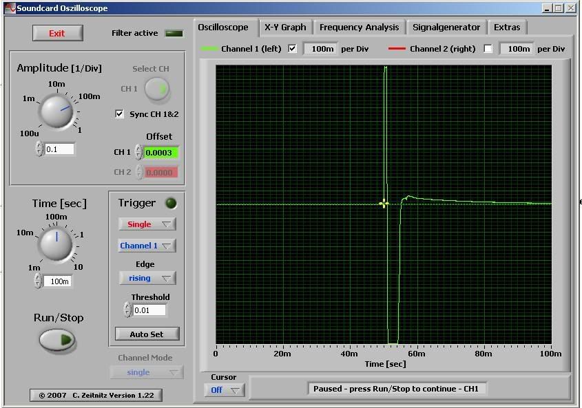
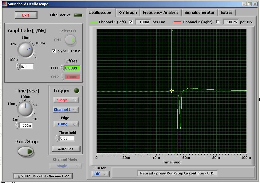
Edit: Now all that remains is to both calibrate the coil, and also build the integrator
Edit 2:
Videos of the 300V and 430V tests, kinda boring but if you are interested:


aonomus, Thu Jan 29 2009, 02:12AM
So I've constructed the coil and given it a whirl using my coilgun and it seems to work ok. I don't have a integrator for it, it is only the rogowski coil itself plugged into a scope. Some construction photos:

I used a luer lock fittings (from syringes and fluid handling stuff) for the connector


A closeup of the coil.
I used 20ft of RG6 with a twist-on BNC connector (no crimper), 30AWG magnet wire for the coil itself.
For my first test I used my biggest induction motor fan on 120VAC and got this:

Test setup

Sinewave: 120VAC
Choppy wave: Current
My second test was with my coilgun with different projectiles and voltages, and worked out pretty well. I captured the waveforms using my laptop's soundcard as a cheap DSO, however I maxed out the card and the waveforms got clipped at higher powers.


Edit: Now all that remains is to both calibrate the coil, and also build the integrator
Edit 2:
Videos of the 300V and 430V tests, kinda boring but if you are interested:


Re: Rogowski coil construction
likewhat, Thu Jan 29 2009, 02:31AM
interesting results. A few questions/comments.
How do you terminate the coil. It is built in a 50 ohm cable right? are you terminating it into a 50 ohm connection, if not it will have weird reflections and you will see them on your scope.
Unless you buy something that comes with a calibration and you are using it within the design parameters you pretty much have to calibrate it for the frequency you are using it on. So if you need to measure something that puts out 1000 amps with 1 us rise time you should calibrate it on a 1 us rise time pulse that has an amperage output you can reliably measure.
If you are maxing out your card you should get some attenuators for it. I dont know how much they cost cause we just have piles of them in the lab I work at but they are super useful, that way you dont have to build a different probe for every different machine you measure current on.
Re: Rogowski coil construction
aonomus, Thu Jan 29 2009, 02:46AM
Well in you can see its a 75 ohm cable, the coil itself has 2 connections, one end to shield, one end to center conductor. I sadly couldn't find any 50ohm cable, perhaps one day I will build a new one on a 50ohm cable.
What would the reflection look like on a scope, I've tried low frequency, high frequency, and pulse and I haven't gotten any visible reflections, although on some HF measurements I got unstable triggering on my scope, however I suspect that is due to the HF source being the charger circuit on my coilgun, and that it naturally fluctuates...
I'll have to read up on calibrating it anyway.
aonomus, Thu Jan 29 2009, 02:46AM
Well in
 you can see its a 75 ohm cable, the coil itself has 2 connections, one end to shield, one end to center conductor. I sadly couldn't find any 50ohm cable, perhaps one day I will build a new one on a 50ohm cable.
What would the reflection look like on a scope, I've tried low frequency, high frequency, and pulse and I haven't gotten any visible reflections, although on some HF measurements I got unstable triggering on my scope, however I suspect that is due to the HF source being the charger circuit on my coilgun, and that it naturally fluctuates...
I'll have to read up on calibrating it anyway.
Re: Rogowski coil construction
rp181, Thu Jan 29 2009, 04:47AM
I was winding one, and i was wondering, what if the loop is too big? can it be too big (within limits)?
rp181, Thu Jan 29 2009, 04:47AM
I was winding one, and i was wondering, what if the loop is too big? can it be too big (within limits)?
Re: Rogowski coil construction
101111, Thu Jan 29 2009, 12:03PM
About impedance it connectors and cables on this topic:
I can hardly see that it matters, as far as I know this is only relevant when it come to high frequencies.
I think as long as the cable are shielded it should be O.K, but I might be wrong..
101111, Thu Jan 29 2009, 12:03PM
About impedance it connectors and cables on this topic:
I can hardly see that it matters, as far as I know this is only relevant when it come to high frequencies.
I think as long as the cable are shielded it should be O.K, but I might be wrong..
Re: Rogowski coil construction
rp181, Thu Jan 29 2009, 11:34PM
Hey all,
I just finished winding a coil. Its wound with 30 AWG. I was talking to aonomus about just putting the coil next together, instead of a Tee. Would this method work? Here are some pics:


BTW, in the first pic, the ends are closer together then they appear. one end was bent up a little.
EDIT: I just tried it with a 3900uf capacitor charged to 160v. The wave is nice and clean, and it is also cut off. It wasn't a coilgun, it was hard shorted with a SCR. Im going to try mains now, ile post pics when im done with that.
rp181, Thu Jan 29 2009, 11:34PM
Hey all,
I just finished winding a coil. Its wound with 30 AWG. I was talking to aonomus about just putting the coil next together, instead of a Tee. Would this method work? Here are some pics:


BTW, in the first pic, the ends are closer together then they appear. one end was bent up a little.
EDIT: I just tried it with a 3900uf capacitor charged to 160v. The wave is nice and clean, and it is also cut off. It wasn't a coilgun, it was hard shorted with a SCR. Im going to try mains now, ile post pics when im done with that.
Re: Rogowski coil construction
aonomus, Tue Feb 03 2009, 10:59PM
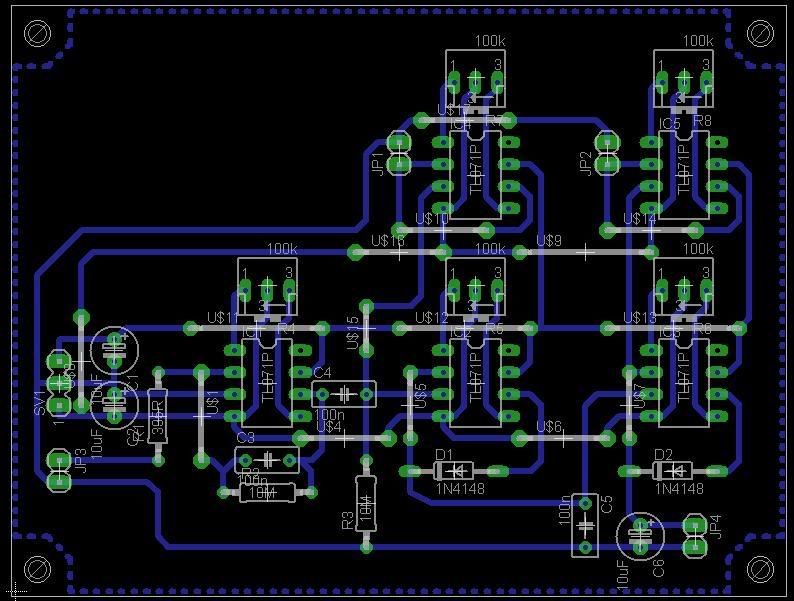
So I've done up a schematic, slightly modified from Dalus's link (post #4 I believe), its a bit of a monstrosity, but its single sided and uses a bunch of jumpers. I have modified the board to use fewer since then, but its still pretty bad....
aonomus, Tue Feb 03 2009, 10:59PM
So I've done up a schematic, slightly modified from Dalus's link (post #4 I believe), its a bit of a monstrosity, but its single sided and uses a bunch of jumpers. I have modified the board to use fewer since then, but its still pretty bad....

Re: Rogowski coil construction
rp181, Wed Feb 04 2009, 02:19AM
nice, where do you plan on getting the TL071P's?
rp181, Wed Feb 04 2009, 02:19AM
nice, where do you plan on getting the TL071P's?
Re: Rogowski coil construction
aonomus, Wed Feb 04 2009, 03:28AM
Well TDU's active integrator is very similar to this, including the opamp (TL071), however discussions with Steve Conner said that I'd need opamps 10-100x faster than the time constant of the pulse (assuming a 1-10ms pulse, that means the TL071 is too slow). Since TDU's worked with TL071's, I will try the design with this first, and if they are too slow and I get residual voltage offset, I'll switch to a pin-equivalent faster opamp.
Re: Rogowski coil construction
rp181, Wed Feb 04 2009, 04:33AM
What is the intended application? I was reading some paper's, and passive will suffice for some. Since mine will be a permanent installation, passive will work fine.
rp181, Wed Feb 04 2009, 04:33AM
What is the intended application? I was reading some paper's, and passive will suffice for some. Since mine will be a permanent installation, passive will work fine.
Re: Rogowski coil construction
aonomus, Thu Feb 12 2009, 04:22AM
The intended application is for monitoring my capacitor bank's current waveform, the coil itself gives dI/dt, the change in current over time, and the integrator is just a couple of opamps, some features are just to play around with to see if its useful at all.
I just completed the integrator, although I have a few wires to hook up, it looks promising. In a few days I will have the time to completely wire the input/output connectors and test the integrator. The waveforms you see above are dI/dt, I'll try to get a captured waveform soon, and only calibration is left to finish.
Another bonus is that it would appear that the output is reduced in voltage, I may have to add a separate gain stage with a 1x, 10x, 100x selection switch just to get the desired amplitude...
Re: Rogowski coil construction
rp181, Thu Feb 12 2009, 04:55AM
On my PC, The drop is low enough that the time has to be on the lowest setting on the dial, and sometimes lower. I don't think a gain stage is necessary.
rp181, Thu Feb 12 2009, 04:55AM
On my PC, The drop is low enough that the time has to be on the lowest setting on the dial, and sometimes lower. I don't think a gain stage is necessary.
Re: Rogowski coil construction
ungkuiskandar, Mon Apr 27 2009, 08:25PM
hei aonomus, i have recently PMed you. not sure if you have receive it or not, but is it possible if i could contact you ?
ungkuiskandar, Mon Apr 27 2009, 08:25PM
hei aonomus, i have recently PMed you. not sure if you have receive it or not, but is it possible if i could contact you ?
Re: Rogowski coil construction
teravolt, Tue Apr 28 2009, 04:14AM
a lot of thease ciols are pure inductance and may have there own resonant frequencies. if you use a core and spread the windings apart and add a parallel noninductive resistor your response will be more flat. the core bandwidth will detrmin the frequency response. person probes are made this way I believe
Re: Rogowski coil construction
ungkuiskandar, Thu Apr 30 2009, 12:49AM
hey aenomous, about the schematic diagram, how do u actually plan it? like im planning to use my coil just for instrumentation. perhaps having a frequency of 1kHz is enough.
so do u think my schematic diagram will be as complicated as yours?
if i were to use 741 op amp model, could i just use 2 resistors r1,and r2, and a capacitor c1,
with the capacitor and r2 feeded back to the opamp and r1 is in series with the input?
Re: Rogowski coil construction
ungkuiskandar, Thu Apr 30 2009, 04:47PM
hi guys. Is it possible if any of u could give me advice online? I have built my own rogowski coil using a 75 ohms co-axial cable about a meter long.
I have wind it up using a wire and turn in 282 times around the coil. I plan to use it for instrumentation purposes.
The voltage range that i have decided is = 1mV - 10V
and operating current range to be = 1mA - 1A.
the frequency range should be about = 1Hz - 1kHz
i have then make my own calculations, to get the integrator value, which is
Calculations
E = H di/dt
H= munaught N A
N= 1762.5 turns/m
Radius of the coil = 2 x 10⁻³
Cross sectional Area A = Pi r^2 = 1.26 x 10^-5
Mu naught = 4 pi x 10^-7
So H = 27.9 nVs/A ---------ïƒ coil sensitivity
Say Vout = 10 V, I = 1 A
then
Vout = IH/CR
CR = 27.9/10 = 2.79
If R = 10000 ohms, then C = 2.79/10000 = 0.000279 F = 279 x 10^-6 Farad
does that makes any sense ?
also yesterday i tried my soundcard as an integrator to produce waveform using soundcard as a DSO. I used winscope and online oszilloscope but to no avail. I couldnt get it to work.
I have got pictures of my coil and everything. If any of u r interested i could email it to you, then maybe u could help me figure out what went wrong.
Print this page