
Maximum speed in multistage accelerator with identical windings
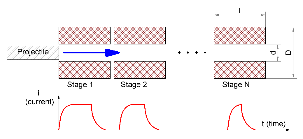
_Eugen_, Sun Dec 23 2018, 12:35PMLimitations for velocity of projectile are investigated for a multistage reluctance accelerator having identical coils. Geometrical parameters of winding are used as basis, assuming an overdamped system fed from large common capacitance.
Re: Maximum speed in multistage accelerator with identical windings
_Eugen_, Sun Dec 23 2018, 12:41PM
Details of the calculation can be examined on this page.
Here are the results and discussion.
_Eugen_, Sun Dec 23 2018, 12:41PM
Details of the calculation can be examined on this page.
Here are the results and discussion.

Re: Maximum speed in multistage accelerator with identical windings
_Eugen_, Sun Dec 23 2018, 12:46PM
Below are maximum projectile velocities tabulated for various inside coil diamaters d, outer diameters D and length l.
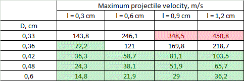
d=0,3 cm
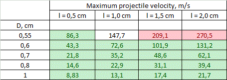
d=0,5 cm
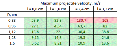
d=0,8 cm
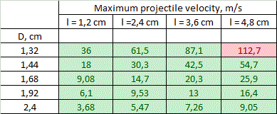
d=1,2 cm
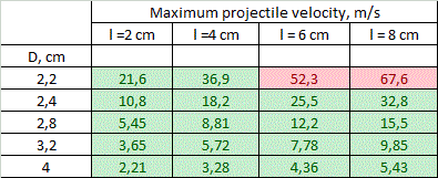
d=2,0 cm
_Eugen_, Sun Dec 23 2018, 12:46PM
Below are maximum projectile velocities tabulated for various inside coil diamaters d, outer diameters D and length l.

d=0,3 cm

d=0,5 cm

d=0,8 cm

d=1,2 cm

d=2,0 cm
Re: Maximum speed in multistage accelerator with identical windings
_Eugen_, Sun Dec 23 2018, 12:52PM
_Eugen_, Sun Dec 23 2018, 12:52PM
Limitations layed by ohmic heat and weight of capacitor were taken into account. Red-colored cells of the tables correspond to the capacitor mass exceeding a resonable limit. Range of values for which no overheat occurs, is covered with green color.
Generally, we can see that both limits under concern work in one direction, constraining vmax for accelerators with thin long windings. "Heat" limit plays major role for the small calibers. At 8 mm bore the borders for the limits coincide, and for 12 and 20 mm bores "green zone" covers all the tables, and only "mass limit" manifests.
Other limiting factors like wight of the coils can also be taken into account by a similar way.
Re: Maximum speed in multistage accelerator with identical windings
_Eugen_, Sun Dec 23 2018, 12:56PM
_Eugen_, Sun Dec 23 2018, 12:56PM
Conclusions and discussion.
Following conclusions can be made.
1) On the assumption of the geometrical properties of multistage accelerators with identical coils, theoretical velocities of 100..130 m/s are achievable for the calibers of less than 8 mm. The highest-speed caliber is about 5 mm.
2) The obstacles on the way to higher speeds are overheat of the coils for small-bore coilguns, and huge mass of the power capacitor for large-bore ones. For 20 mm and larger calibers velocities of more than 70 m/s cannot be obtained exclusively because of geometry of the coils (even without the "weight" limitation).
3) vmax falls with coil's thickness growth and length decrease. The thickness is more critical - the velocity decreases by an order of magnitude when the outer diameter grows from 1,1·d to 2·d, and only triply when relative length increases from d to 4·d.
It is clear that small calibers are the most attractive for breakthrough to high velocities. They are even more tempting if we note that mass is not the only reason which limits us in a portable system - the length acts, too. 16 stages of 12 mm gaussgun with l/d = 4 ratio would make 80..90 cm in total (assuming some additional place for detectors and other elements of the construction) - this is a bit excessively. For 3 mm-bore coilgun total length would be 20..30 cm only.
The first table says that supersonic velocities can be obtained theoretically. Сooiling of windings with liquid nitrogen or Peltier modules can be used prior to shot to prevent overheat (such a method was proposed by many authors for induction launchers). In this case, the efficiency would increase not only because of active resistance reduction, but also because of the speed growth (see here).
As for large caliber coilguns (more 10 mm) with identical windings, the results above make us claim that velocities of projectile of more than 100 m/s cannot be obtained with state-of-art electronics (unless some tricky technologies are utilized like recuperation).
Re: Maximum speed in multistage accelerator with identical windings
Sulaiman, Sun Dec 23 2018, 02:20PM
As mentioned in the link provided,
the wire gauge, turns and coil dimensions would normally not be the same for each coil.
For a still fairly simple analysis why not maintain coil geometry
but use thinner wire at the start with the wire getting appropriately* thicker/more strands for successive stages.
* this is the hard part
Re: Maximum speed in multistage accelerator with identical windings
V2006, Mon Dec 24 2018, 08:44AM
Re: "Limitations layed by ohmic heat and weight of capacitor were taken into account. Red-colored cells of the tables correspond to the capacitor mass exceeding a resonable limit."
- The size and weight of the capacitors have ceased to be a problem:

(12V , 100A using Super capacitors , Amazing idea)
V2006, Mon Dec 24 2018, 08:44AM
Re: "Limitations layed by ohmic heat and weight of capacitor were taken into account. Red-colored cells of the tables correspond to the capacitor mass exceeding a resonable limit."
- The size and weight of the capacitors have ceased to be a problem:

(12V , 100A using Super capacitors , Amazing idea)
Re: Maximum speed in multistage accelerator with identical windings
_Eugen_, Mon Dec 24 2018, 04:22PM
To V2006:
No, the supercapacitors have too much serial resistance. The details can be found elsewhere. Besides, voltage is too low - LiPo batteries would be more optimal.
_Eugen_, Mon Dec 24 2018, 04:22PM
To Sulaiman:
May be I'll try such an analysis later. The problem is that inductance varies vary fast with wire gauge d (in inverse proporion to (d in 4th power).
Anyway, the identity of the stages is lost here.
For a still fairly simple analysis why not maintain coil geometry
but use thinner wire at the start with the wire getting appropriately* thicker/more strands for successive stages.
May be I'll try such an analysis later. The problem is that inductance varies vary fast with wire gauge d (in inverse proporion to (d in 4th power).
Anyway, the identity of the stages is lost here.
To V2006:
The size and weight of the capacitors have ceased to be a problem
No, the supercapacitors have too much serial resistance. The details can be found elsewhere. Besides, voltage is too low - LiPo batteries would be more optimal.
Re: Maximum speed in multistage accelerator with identical windings
V2006, Mon Dec 24 2018, 05:07PM
To _Eugen_ :
When I bought a 450 Volt 8200 microfarad, I also read everything about them (for example, the limits on the discharge current.)
There is a video where 2.7 Volt 500 Farad is used for spot welding.
And there is a 24 volt assembly (total capacity 10 Farad). So you can make an assembly at 70 - 100 volts. This is already enough. Probably possible and 300 volts.
Re: Maximum speed in multistage accelerator with identical windings
hen918, Mon Dec 24 2018, 05:57PM
A low internal resistance 120 F supercapacitor has an ESR of 8 mR . To make 24 V ish, you would need 9 of them in series. -> 72 mR. For 100 V: 288 mR. This is several orders of magnitude larger than the resistance of the coil. A normal 100 V 0.1 F electrolytic has an internal resistance of 8 mR
  .
.
What advantage does the supercap have? I can't see one.
On a side note, even a 4500 F supercapacitor can't spot weld properly (I have tried). Again, this is due to the internal resistance; you need several hundred amps, and 2.7/(sum of resistances) cannot provide that, even using really chunky wire. It is probably possible to spot weld with a series/parallel combination of supercaps, but there isn't much point unless you happen to have a lot of them
hen918, Mon Dec 24 2018, 05:57PM
V2006 wrote ...
To _Eugen_ :
When I bought a 450 Volt 8200 microfarad, I also read everything about them (for example, the limits on the discharge current.)
There is a video where 2.7 Volt 500 Farad is used for spot welding.
And there is a 24 volt assembly (total capacity 10 Farad). So you can make an assembly at 70 - 100 volts. This is already enough. Probably possible and 300 volts.
A low internal resistance 120 F supercapacitor has an ESR of 8 mR
 . To make 24 V ish, you would need 9 of them in series. -> 72 mR. For 100 V: 288 mR. This is several orders of magnitude larger than the resistance of the coil. A normal 100 V 0.1 F electrolytic has an internal resistance of 8 mR
  .
.What advantage does the supercap have? I can't see one.
On a side note, even a 4500 F supercapacitor can't spot weld properly (I have tried). Again, this is due to the internal resistance; you need several hundred amps, and 2.7/(sum of resistances) cannot provide that, even using really chunky wire. It is probably possible to spot weld with a series/parallel combination of supercaps, but there isn't much point unless you happen to have a lot of them
Re: Maximum speed in multistage accelerator with identical windings
_Eugen_, Mon Dec 24 2018, 05:59PM
To V2006.
_Eugen_, Mon Dec 24 2018, 05:59PM
To V2006.
I don't argue that supercaps have more energy capacity than common electrolytic ones. But their intrinsic characteristic is very low voltage which prevents them from being used in coilguns. We can of course connect them in series like you suggest, but such decision is not reasonable for the cost issues - the species you linked to are about 40 S per unit. To have 25...30 volts (lower voltages are impractical because of parasitic resistances presenting in any construction) we should use 10 pieces - about 400 S only for the power supply of our hypothetical coilgun. It is simpler to connect LiPos in series and get comparable power at higher volteges like guys from Arcflashlabs did. Besides, supercaps still need external accus to support their charge on a desirable level.
Anyway, all these speculations (interesting of course) are out of the scope of my investigation - I suggested a conventional coilgun structure equipped with electrolytic capacitors.
Anyway, all these speculations (interesting of course) are out of the scope of my investigation - I suggested a conventional coilgun structure equipped with electrolytic capacitors.
Re: Maximum speed in multistage accelerator with identical windings
V2006, Mon Dec 24 2018, 07:01PM
To hen918
Supercapacitors are much smaller and lighter than ordinary electrolytic capacitors.
I also doubted the properties of supercapacitors. Until I saw it:
Spot welder using 500Farad super capacitor , Ultra capacitor as spot welder

V2006, Mon Dec 24 2018, 07:01PM
To hen918
Supercapacitors are much smaller and lighter than ordinary electrolytic capacitors.
I also doubted the properties of supercapacitors. Until I saw it:
Spot welder using 500Farad super capacitor , Ultra capacitor as spot welder

Re: Maximum speed in multistage accelerator with identical windings
V2006, Mon Dec 24 2018, 07:15PM
On sales prices are much lower:
2.7 Ð’ 500F 35*60MM - US $2,80
2.7 Ð’ 100F La- US $1,97
24 Ð’ 10x100F - US $39,90
With lithium batteries it was already full of experiments. And with series-connected supercapacitors (in the amount of 20 - 30 pieces) no. The world has changed since the collapse of the USSR.
When I have a box of supercapacitors, I will make an electromagnetic accelerator of the most incredible power.
Re: Maximum speed in multistage accelerator with identical windings
_Eugen_, Mon Dec 24 2018, 08:21PM
OK, I'm sure you will create an extraordinary supercapacitor coilgun which will shake the world. I wish you good luck.
But I won't discuss this theme any more as it is out of topic of this thread.
_Eugen_, Mon Dec 24 2018, 08:21PM
OK, I'm sure you will create an extraordinary supercapacitor coilgun which will shake the world. I wish you good luck.
But I won't discuss this theme any more as it is out of topic of this thread.
Re: Maximum speed in multistage accelerator with identical windings
klugesmith, Mon Dec 24 2018, 09:59PM
Looks like nice work you did, Eugen.
Regarding supercapacitors, I will join the chorus saying that they're great for storing energy, but inferior to electrolytics for delivering power. (look up Ragone plot).
In another recent 4hv thread:
we saw that internal resistance makes it impossible to discharge a supercap faster than time constant of about 1 second.
( Consistent with RC numbers given in this thread. Series or parallel banks of multiple caps have the same RC product as an individual capacitor. ) And that's with a short circuit, which delivers zero power to the load (because zero voltage), and is abusive to the capacitor. Of course this sub-forum is full of stories about abusing capacitors.
To deliver the most power from a supercapacitor to a resistive load, the load R needs to match the capacitor's internal R. Then when switch is closed, initial load voltage is 1/2 of initial capacitor voltage. Half of the stored energy goes to the load and half is lost inside the capacitor, warming it by a fraction of a degree. To get more of the energy to the load, discharge needs to be slower. Say, 10 seconds. Appropriate for accelerating a vehicle that makes frequent stops.
It's slightly different in coilguns, where inductance and stored energy in the coil are significant. That doesn't change the fact that aluminum electrolytic caps can always deliver more power than supercaps of similar size and weight. At lower powers, appropriate for both kinds of capacitor, the supercapacitor can run much longer. Coilgun pulses are too short for supercaps to be efficient, unless you want to get many shots out of a single charge.
klugesmith, Mon Dec 24 2018, 09:59PM
Looks like nice work you did, Eugen.
Regarding supercapacitors, I will join the chorus saying that they're great for storing energy, but inferior to electrolytics for delivering power. (look up Ragone plot).
In another recent 4hv thread:

we saw that internal resistance makes it impossible to discharge a supercap faster than time constant of about 1 second.
( Consistent with RC numbers given in this thread. Series or parallel banks of multiple caps have the same RC product as an individual capacitor. ) And that's with a short circuit, which delivers zero power to the load (because zero voltage), and is abusive to the capacitor. Of course this sub-forum is full of stories about abusing capacitors.

To deliver the most power from a supercapacitor to a resistive load, the load R needs to match the capacitor's internal R. Then when switch is closed, initial load voltage is 1/2 of initial capacitor voltage. Half of the stored energy goes to the load and half is lost inside the capacitor, warming it by a fraction of a degree. To get more of the energy to the load, discharge needs to be slower. Say, 10 seconds. Appropriate for accelerating a vehicle that makes frequent stops.
It's slightly different in coilguns, where inductance and stored energy in the coil are significant. That doesn't change the fact that aluminum electrolytic caps can always deliver more power than supercaps of similar size and weight. At lower powers, appropriate for both kinds of capacitor, the supercapacitor can run much longer. Coilgun pulses are too short for supercaps to be efficient, unless you want to get many shots out of a single charge.
Re: Maximum speed in multistage accelerator with identical windings
_Eugen_, Tue Dec 25 2018, 10:33AM
_Eugen_, Tue Dec 25 2018, 10:33AM
In general, from the point of view of my calculation, it's no matter what power source is used in a specific accelerator. It may be conventional eletrolytics, LiPos and other accus, or supercaps. The only influence is the more capacitance it has - the closer a system is to "overdamped" type and more exact are the formulae. Supercaps and LiPos can be suggested as caps with very large capacitance - that's the only difference.
I just tried to emphasize that geometrical properties of the coils play major role in limiting the velocity of projectile - such that it may be assessed by the geometry itself with minimal additional information. A limitation concerning mass of the power source is only one example of how the demands layed on a portable system could shrink a range of results we got. Many other limitations may be taken into account, too, but the principle of the calculation will stay unchanged.
I just tried to emphasize that geometrical properties of the coils play major role in limiting the velocity of projectile - such that it may be assessed by the geometry itself with minimal additional information. A limitation concerning mass of the power source is only one example of how the demands layed on a portable system could shrink a range of results we got. Many other limitations may be taken into account, too, but the principle of the calculation will stay unchanged.
Re: Maximum speed in multistage accelerator with identical windings
Uspring, Tue Jan 01 2019, 04:52PM
In your model max velocity seems to be limited by the slow decay of current after the coil is shorted. If current and with it, the magnetic field lasts too long, you will have suckback. Decay time is about L/R in your circuit, where L is the coils inductance and R its resistance. Thinner coils (D-d small) have a higher resistance or more precisely a lower L/R, which makes them suitable for higher velocities. By choosing turn off earlier, i.e. before the projectile is in the middle of the coil, that can be improved somewhat.
Much better would be a adding a resistance in the discharge path of your circuit. That would decrease decay time and at the same time allow for a less resistive, i.e. thicker coil. That will also increase efficiency.
Re: Maximum speed in multistage accelerator with identical windings
_Eugen_, Wed Jan 02 2019, 09:38AM
to Uspring:
Yes you are right, the decay of current is another limiting factor. But it depends strongly on a specific circuit utilized in a coilgun (see below), so it isn't subject to simple analysis. May be my next investigation will be dedicated to this effect. As for the simple "freewheeling" scheme (without an additional resistance and other measures) you wrote about, it is used very rarely because current indeed decays very slowly here.
The problem is that the accelerating force has its maximum near to the middle of the coil, too. So the early turn-off the coil would substantially decrease efficiency of our accelerator. More promising is early turn-on - not when a projectile enters the coil, but in advance, especially for high initial velocities.
In general, current -damping schemes may be divided into 3 groups depending on what measure is used to absorb inductive energy of the coil after turn-off:
1) Simple resistive (or R+D) - its just what you wrote about.
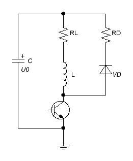
As I show here, damping resistor is set by a fairly simple equation. The point is that it must have considerable (in comparison to the coil's) resistace to enforce the decay of current, which automatically means high voltage spike on a power switch - the faster current decays, the higher the voltage is. As an example, in this construction its author had to use high-voltage IGBTs while the power source is only 50 V battery, and still he wrote that he faced a problem of the switch failure because of the inductive spike.
2) Varistor circuit.
In this scheme a special component -varistor - is connected in parralel to the switch or to the coil. It has nearly constant breakdown voltage, so it ensures nearly linear fast current decay. A kind of such circuit is a scheme where only MOSFET is used (without any additional damping circuitry) and all the energy is absorbed by its internal Zener diode. Very careful calculation must be provided here to be sure that the energy doesn't exceed the limits of a specific transistor. As a rule, only the most powerful switches in TO-247 cases may be used in such configuration.
3) Halfbridge circuits.
The inverse initail voltage is applied to the coil in this case, so the current decreases as fast as it has increased. The main feature of halfbridge is its ability for recuperation of energy back into the capacitor. I examined this question in details here and here.
But the halfridge is not an ideal from the point of view of fast current decay - its optimal current form is close to triangle, so we must choose the coils attentively in accordance to this circuit and conduct FEMM or other modelling to be sure that no suck-back effect occurs.
_Eugen_, Wed Jan 02 2019, 09:38AM
to Uspring:
In your model max velocity seems to be limited by the slow decay of current after the coil is shorted. If current and with it, the magnetic field lasts too long, you will have suckback. Decay time is about L/R in your circuit, where L is the coils inductance and R its resistance. Thinner coils (D-d small) have a higher resistance or more precisely a lower L/R, which makes them suitable for higher velocities.
Yes you are right, the decay of current is another limiting factor. But it depends strongly on a specific circuit utilized in a coilgun (see below), so it isn't subject to simple analysis. May be my next investigation will be dedicated to this effect. As for the simple "freewheeling" scheme (without an additional resistance and other measures) you wrote about, it is used very rarely because current indeed decays very slowly here.
By choosing turn off earlier, i.e. before the projectile is in the middle of the coil, that can be improved somewhat.
The problem is that the accelerating force has its maximum near to the middle of the coil, too. So the early turn-off the coil would substantially decrease efficiency of our accelerator. More promising is early turn-on - not when a projectile enters the coil, but in advance, especially for high initial velocities.
Much better would be a adding a resistance in the discharge path of your circuit. That would decrease decay time and at the same time allow for a less resistive, i.e. thicker coil. That will also increase efficiency.
In general, current -damping schemes may be divided into 3 groups depending on what measure is used to absorb inductive energy of the coil after turn-off:
1) Simple resistive (or R+D) - its just what you wrote about.

As I show here, damping resistor is set by a fairly simple equation. The point is that it must have considerable (in comparison to the coil's) resistace to enforce the decay of current, which automatically means high voltage spike on a power switch - the faster current decays, the higher the voltage is. As an example, in this construction its author had to use high-voltage IGBTs while the power source is only 50 V battery, and still he wrote that he faced a problem of the switch failure because of the inductive spike.
2) Varistor circuit.
In this scheme a special component -varistor - is connected in parralel to the switch or to the coil. It has nearly constant breakdown voltage, so it ensures nearly linear fast current decay. A kind of such circuit is a scheme where only MOSFET is used (without any additional damping circuitry) and all the energy is absorbed by its internal Zener diode. Very careful calculation must be provided here to be sure that the energy doesn't exceed the limits of a specific transistor. As a rule, only the most powerful switches in TO-247 cases may be used in such configuration.
3) Halfbridge circuits.
The inverse initail voltage is applied to the coil in this case, so the current decreases as fast as it has increased. The main feature of halfbridge is its ability for recuperation of energy back into the capacitor. I examined this question in details here and here.
But the halfridge is not an ideal from the point of view of fast current decay - its optimal current form is close to triangle, so we must choose the coils attentively in accordance to this circuit and conduct FEMM or other modelling to be sure that no suck-back effect occurs.
Re: Maximum speed in multistage accelerator with identical windings
Uspring, Wed Jan 02 2019, 12:11PM
I think, you are choosing the damping resistor RD too large. Select it in a way, that the initial current through it will cause a voltage drop of about U0. That will cause a decay time of the same duration as the charge up time and a transient across the transistor of 2*U0. The current pulse length is then twice the charge up time (=on time of transistor). The current pulse length can be chosen to fit into the interval between the projectile entering the coil and its middle position.
In order to achieve a sufficiently high current into the coil for fast projectiles and corresponding short pulse lengths, the inductance of the coil needs to be made accordingly small. Large velocities seem feasible.
Uspring, Wed Jan 02 2019, 12:11PM
As I show here, damping resistor is set by a fairly simple equation. The point is that it must have considerable (in comparison to the coil's) resistace to enforce the decay of current, which automatically means high voltage spike on a power switch - the faster current decays, the higher the voltage is. As an example, in this construction its author had to use high-voltage IGBTs while the power source is only 50 V battery, and still he wrote that he faced a problem of the switch failure because of the inductive spike.
I think, you are choosing the damping resistor RD too large. Select it in a way, that the initial current through it will cause a voltage drop of about U0. That will cause a decay time of the same duration as the charge up time and a transient across the transistor of 2*U0. The current pulse length is then twice the charge up time (=on time of transistor). The current pulse length can be chosen to fit into the interval between the projectile entering the coil and its middle position.
In order to achieve a sufficiently high current into the coil for fast projectiles and corresponding short pulse lengths, the inductance of the coil needs to be made accordingly small. Large velocities seem feasible.
Re: Maximum speed in multistage accelerator with identical windings
_Eugen_, Wed Jan 02 2019, 05:53PM
Unfortunately, such a simple approach cannot yield high efficiency acceleration. The problem is that we must tune the current in such a way that it coincides with the form of pulling force, which is highly assymetrical. The example below is from Barry's site, but can also be obtained by FEMM for any another coil:

We can see that maximum force is situated near the center of the coil (or, more exactly, accords to the moment when the projectile is nearly fully pulled into the coil). That is why the current's maximum must be somewhere about that, too. So an ideal current form should be like sawtooth with long front and very fast end,nearly coinciding with the moment when the projectile's center reaches the center of the coil.
_Eugen_, Wed Jan 02 2019, 05:53PM
That will cause a decay time of the same duration as the charge up time and a transient across the transistor of 2*U0. The current pulse length is then twice the charge up time (=on time of transistor). The current pulse length can be chosen to fit into the interval between the projectile entering the coil and its middle position
Unfortunately, such a simple approach cannot yield high efficiency acceleration. The problem is that we must tune the current in such a way that it coincides with the form of pulling force, which is highly assymetrical. The example below is from Barry's site, but can also be obtained by FEMM for any another coil:

We can see that maximum force is situated near the center of the coil (or, more exactly, accords to the moment when the projectile is nearly fully pulled into the coil). That is why the current's maximum must be somewhere about that, too. So an ideal current form should be like sawtooth with long front and very fast end,nearly coinciding with the moment when the projectile's center reaches the center of the coil.
Re: Maximum speed in multistage accelerator with identical windings
Uspring, Thu Jan 03 2019, 11:33AM
I agree. Essential is a fast turn off of the current. That is the reason for my suggestion of applying a reverse voltage to the coil, e.g. by some RD>0. A large RD will have the drawback of requiring a higher voltage transistor. On the other hand, an RD=0, as your tables imply, leaves you at the mercy of the coils internal resistance to reduce the current. That involves thin wires and eventually leads to heat up.
So I guess it is just a design choice.
Re: Maximum speed in multistage accelerator with identical windings
Sulaiman, Thu Jan 03 2019, 11:51AM
A question relevant to the 'snubbing' of coilguns :
If a coil gun is X% efficient then were does the (100 - X)% go to ?
Sulaiman, Thu Jan 03 2019, 11:51AM
A question relevant to the 'snubbing' of coilguns :
If a coil gun is X% efficient then were does the (100 - X)% go to ?
Re: Maximum speed in multistage accelerator with identical windings
_Eugen_, Thu Jan 03 2019, 02:13PM
to Uspring:
Well, I didn't suggest Rd=0 or any another value of the damping resistor. I only said that I didn't include this process into my investigation (see remark 1 to fig. 1).
to Sulaiman:
Maybe you hint on how much energy dissipates on snubber circuitry? It is interesting question. As all the energy dissipated after turn-off is stored in magnetic field of the coil, it usually makes no more than 10.....50 % of the whole energy wasted per shot. Then it is dissipated in Rd and RL in proprotion to their resistances.
_Eugen_, Thu Jan 03 2019, 02:13PM
to Uspring:
On the other hand, an RD=0, as your tables imply, leaves you at the mercy of the coils internal resistance to reduce the current
Well, I didn't suggest Rd=0 or any another value of the damping resistor. I only said that I didn't include this process into my investigation (see remark 1 to fig. 1).
to Sulaiman:
Maybe you hint on how much energy dissipates on snubber circuitry? It is interesting question. As all the energy dissipated after turn-off is stored in magnetic field of the coil, it usually makes no more than 10.....50 % of the whole energy wasted per shot. Then it is dissipated in Rd and RL in proprotion to their resistances.
Re: Maximum speed in multistage accelerator with identical windings
Uspring, Sun Jan 06 2019, 05:50PM
I was wondering, why the tables show the highest possible velocities, when they are thinnest. I believe that can be traced your requirement of tmax < t0. tmax is about L/R, so a small t0 implies a big R and therefore a thin coil. That is a bit strange, because a thicker coil with the same L but a smaller R will provide more acceleration.
A drawback of such a thicker coil will be the higher current draw of the first stage, where the max current is limited by the resistance and not the inductance.
Re: Maximum speed in multistage accelerator with identical windings
_Eugen_, Wed Jan 09 2019, 08:54AM
Yes, you are absolutely right.
Well, there is not a simple dependence between thickness and acceleration efficiency (while keeping a constant R). It has some broad maximum indeed, but it is not strictly tied to thicker coil - a thinner one can be more efficient depending on initial velocity of projectile, its length etc.
In my investigation the additional problem is that all the coils must be identical - it means that even if for some of them we find the efficiency to be higher for thicker winding (it corresponds to nearly triangle pulseform), the next (similar) coils would have low (and decreasing with the stage nubmer) influence on projectile acceleration, as their current cannot reach any substantial value during the accelerated body is moving inside them (although their absolute efficiency could be really high).
That is a root paradox of the gauss-building - decreasing the power (current) in a coil increases an efficiency, but yields less acceleration. The point is that we must get some final velocity not only with some limited energy reserve (which implies considerable efficiency, indeed) , but within a fixed length of acceleration, too (wich means some minimum speed increment delivered to the projectile at any stage).
_Eugen_, Wed Jan 09 2019, 08:54AM
I believe that can be traced your requirement of tmax < t0. tmax is about L/R, so a small t0 implies a big R and therefore a thin coil.
Yes, you are absolutely right.
That is a bit strange, because a thicker coil with the same L but a smaller R will provide more acceleration.
Well, there is not a simple dependence between thickness and acceleration efficiency (while keeping a constant R). It has some broad maximum indeed, but it is not strictly tied to thicker coil - a thinner one can be more efficient depending on initial velocity of projectile, its length etc.
In my investigation the additional problem is that all the coils must be identical - it means that even if for some of them we find the efficiency to be higher for thicker winding (it corresponds to nearly triangle pulseform), the next (similar) coils would have low (and decreasing with the stage nubmer) influence on projectile acceleration, as their current cannot reach any substantial value during the accelerated body is moving inside them (although their absolute efficiency could be really high).
That is a root paradox of the gauss-building - decreasing the power (current) in a coil increases an efficiency, but yields less acceleration. The point is that we must get some final velocity not only with some limited energy reserve (which implies considerable efficiency, indeed) , but within a fixed length of acceleration, too (wich means some minimum speed increment delivered to the projectile at any stage).
Print this page