
CT performance investigations (Pearson and DIY)
Hydron, Sat Sept 10 2016, 10:47AMI have recently acquired a trio of Pearson wide band current transformers/monitors, so I though that I'd do a bit of work investigating their behavior and that of a home-made DRSSTC CT (constructed for primary current measurement and ZCS bridge switching).
Pearsons:
- 7800, 3525 and 4100
- 0.01, 0.1 and 1V/A respectively into high-Z input, half that into 50R
- 2MHz, 15MHz and 35MHz high frequency 3dB point respectively
- All rated for <6deg phase shift at <10% of high 3dB freq
- Performance measurements on all 3 indicate that they meet datasheet specifications (tested to 10MHz)
- At frequencies >10% of high 3dB freq phase shift is strongly affected by position of wire in central hole
- If wire is well centered phase shift seems significantly lower than Pearson specifies

DIY DRSSTC CT:
- Cascaded CT wound on mystery ferrites, probably EMI suppression ones
- Bottom right holds the first winding, and this is where the wire with current to be measured passes through
- Top (blue) CTs are for bridge ZCS switching and OCD
- Bottom left CT is for measurement, and is terminated with 10R burden and 39R termination resistors inside the BNC
- CTs are ~1000:1 (I think 31:1 x 32:1) overall, giving 0.01V/A output on the BNC (into high-Z input, half that into 50R)
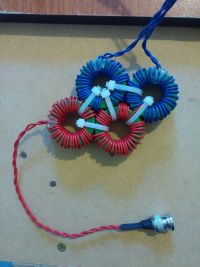
The first problem I ran into was the huge and heavy Pearson 3525 being too heavy to lug from the UK (where I bought it and now live) to NZ (where my DRSSTC lives).
This means that I only had the 7800 and 4100 to compare against the DIY CT, and the only one that can be trusted for low phase shift at frequencies over 200kHz is the 4100.
The 4100 at 1V/A isn't ideal for TC measurements even with a 20dB (10x) attenuator, as it's only rated for 500Apk/5Arms, so I had to get creative:
- At the end of this paper
 , linked in this thread:
  there is a suggestion of cascading a simple CT with a wide band CT for measuring high currents at high frequencies (while giving up low freq perfomance). I had a go at this with a 10:1 CT on a decent ferrite ring, seen below:
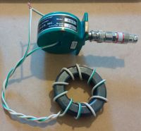
- I compared the 4100 cascaded with a 10:1 DIY CT against the 3525, giving the following result:
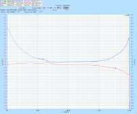
(Note the scales change between captures, and should be checked carefully - e.g. the phase shift above looks big but is under 10deg. Also note that the Pearson 4100 on it's own is only specified for <6deg phase shift between 1.4kHz and 3.5MHz, and the 3525 only up to 1.5MHz)
- This looks really good for frequencies >50kHz - almost as good as the same comparison without the cascaded 10:1 CT!
When I got to NZ I ran a couple of comparisons of the 4100 Pearson (with and without the 10:1 CT on it's input) against the 7800 using the primary circuit of my DRSSTC.
Comparing the 4100 (with 10:1 CT on input and 20dB atten) with the 7800 with the coil running at 850Apk shows no difference other than slightly lower gain on the 7800:
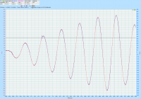
If the 4100 (without the 10:1 CT on the input, but with a 20dB attenuator) is directly compared with the 7800, it has significantly lower susceptibility to noise than the 7800, but it must be remembered that the signal at the CT output is 100x larger than that of the 7800, which is also possibly at a disadvantage being a clamp-on model:
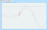
(7800 red, 4100 blue)
Finally I compared the Pearson 4100 (with 10:1 input CT and 20dB attenuator = 0.01V/A) with the 0.01V/A DIY CT, first measuring gain/phase:
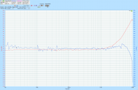
Looks rather good, easily usable to over 1MHz!
Seems the cascaded CT approach used for most DRSSTCs is actually a very good one, and not just because of the low number of windings needed vs a single stage 1000:1 CT
When tested in a DRSSTC, we see that the main advantage of the Pearson in this application is noise immunity (it's shielded, whereas the DIY CT is not). Bridge switching noise, especially on the first couple of transitions where ZCS isn't perfect, clearly shows up:
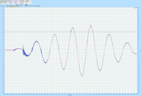
(Red is Pearson, blue is DIY CT)
In conclusion:
The cascaded home-wound approach of CT construction used for DRSSTCs seems to provide extremely good performance for the application. They are not as noise immune as the shielded wide-band commercial models, but this is mostly seen on the initial low-current transitions, seems to clear up as the bridge switches higher current (where accuracy is most needed anyway!). Low frequency performance is likely poor (and certainly won't get anywhere near the 5Hz of the 7800), but it irrelevant in this application.
It can also be seen that the cascaded CT approach can be used to allow a low-current wide-band CT to measure at least an order of magnitude higher current than otherwise possible, while maintaining good noise immunity. Again, this will be high-freq only, but still fine for DRSSTC use. This could be really handy if a 1V/A unit is available cheaply (mine was under 50 USD, albeit with the BNC in bad condition) and higher current capability or a larger center hole is needed.
Something that could be interesting for someone to try in the future is to attempt to shield a DIY CT in a similar manner as done for the commercial CTs (small gap in shield, sometimes even overlapped, to avoid a shorted turn). Might be a good way to get decent performance for TC measurements on a very low budget, without having to luck out on ebay!
Re: CT performance investigations (Pearson and DIY)
Mads Barnkob, Mon Sept 12 2016, 12:31PM
Thank you for putting some time into the work, experiments and then making a lovely topic like this.
You have similar results to other DIY vs. commercial tests, there is however a few others that I can not find right now, but this is one of them:
In regard to shielding, take a look at this picture from the pearson 1330 thread, the sides were actually shorted turns:
Mads Barnkob, Mon Sept 12 2016, 12:31PM
Thank you for putting some time into the work, experiments and then making a lovely topic like this.
You have similar results to other DIY vs. commercial tests, there is however a few others that I can not find right now, but this is one of them:

In regard to shielding, take a look at this picture from the pearson 1330 thread, the sides were actually shorted turns:

Re: CT performance investigations (Pearson and DIY)
Hydron, Mon Sept 12 2016, 01:28PM
I'm not quite sure what you mean - isn't there a gap in the middle of the bore to stop it being a shorted turn? For DIY I was thinking of something similar but on a much smaller scale using foil tape.
Hydron, Mon Sept 12 2016, 01:28PM
Mads Barnkob wrote ...
You have similar results to other DIY vs. commercial tests, there is however a few others that I can not find right now, but this is one of them:
Laughed when I saw this link, guess where I got the part number for the "10:1 CT" ferrite toroid from!You have similar results to other DIY vs. commercial tests, there is however a few others that I can not find right now, but this is one of them:

I'm not quite sure what you mean - isn't there a gap in the middle of the bore to stop it being a shorted turn? For DIY I was thinking of something similar but on a much smaller scale using foil tape.
Re: CT performance investigations (Pearson and DIY)
Mads Barnkob, Tue Sept 13 2016, 06:54AM
There was a small slit between the ends of the two funnels going into the hole. But as I see it, the shielding would still look like a shorted turn to the conductor going through it.
Mads Barnkob, Tue Sept 13 2016, 06:54AM
There was a small slit between the ends of the two funnels going into the hole. But as I see it, the shielding would still look like a shorted turn to the conductor going through it.
Print this page