MCP14E8 as a GDT driver for halfbridge SSTC
Phil33ts, Mon Apr 04 2016, 06:52PMHey guys.
I am designing a small SSTC board (halfbridge).
I want to use as less space and components as it's possible.
I have MCP14E8 chips at hand.
wrote ...
2.0A Dual High-Speed Power MOSFET Driver With Enable
High Peak Output Current: 2.0A (typical)
• Independent Enable Function for Each Driver
Output
• Wide Input Supply Voltage Operating Range:
- 4.5V to 18V
• Low Shoot-Through/Cross-Conduction Current in
Output Stage
• High Capacitive Load Drive Capability:
- tR: 12 ns with 1000 pF load (typical)
- tF: 15 ns with 1000 pF load (typical)
• Short Delay Times: 45 ns (typical)
• Low Supply Current:
- With Logic ‘1’ Input/Enable – 1 mA (typical)
- With Logic ‘0’ Input/Enable – 300 µA (typical)
• Latch-up Protected: Passed JEDEC JESD78A
• Logic Input will Withstand Negative Swing,
up to 5V
• Space-Saving Packages:
- 8-Lead SOIC, PDIP, 6x5 DFN
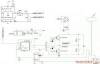
I know that people are usually using two MOSFET driver chips for GDT, but from what I seen several people succedeed using a single one, for instance:


Will MCP14E8 suffice here? How to calculate it? I am aiming at around 200kHz.
Any suggestions?
PS: I have used TC4422/TC4421 pair in the past but they are big and they don't have "enable" pin. They worked well but I need something smaller for this project.

Print this page