
Pearson current monitor model 1330 teardown (100kA)
Mads Barnkob, Thu Feb 25 2016, 08:18PMJanuary 2015.
So, there I was, happy about my latest purchase, a huge and extremely noise immune 100kA current monitor.
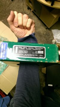
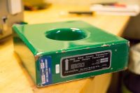
Testing it on a small cap bank did however reveal that something was wrong with it.
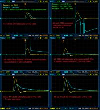
I tried to write Pearson tech support for help with the above image attached.
I have a second hand Pearson current monitor model 1330 that is very ill behaving compared to my model 101.
I made some different measurements with a little description on the bitmaps from my oscilloscope. The measured currents are around 12-16kA.
The 50 Ohm attenuator mentioned in the image is a 50 Ohm -10dB attenuator.
I also tried looping the coax cable through large ferrites for common mode noise suppression without any luck. Neither did it help with a 50 Ohm termination at the oscilloscope input.
I put the different measurements together in a imag
The reply from Pearson
Thank you for the Imgur data. First off, I would not recommend using our current monitors with external terminations other than 50 Ω and 1 MΩ. Our current monitors have a 50 Ω output impedance and the sensitivity is designed to work into an oscilloscope at 1 MΩ input impedance. Using the 50 Ω setting on the oscilloscope with cut the sensitivity in half. Also, the 1330 has an internal series resistor to make the output impedance 50 Ω so putting different loads in parallel with the unit may not have the intended result.
What is the input setting on your oscilloscope? Are you using an external 50 Ω termination with the 50 Ω attenuator? From #1, at ~14 kA I would expect the 1330 channel to be ~10-20 V with a -10 dB attenuator, depending on termination. Since the sensitivity appears off it could be a damaged series resistor or termination resistance. From #2, it looks like the internal termination of the 1330 could have been damaged. Has this unit been used for measuring damped ringing waveforms in the past?
Have you measured the terminal resistance of just the 1330 with the DMM? The 1330 should measure ~46 Ω. If it is much higher this usually indicates a damaged series resistor which can affect the sensitivity when using a 50 Ω load.
I requested help on repairing the unit and all communication stopped after that.
As I had nothing to loose, except money already lost, I decided to take it apart to find a faulty component and maybe repair it on my own.
The green paint is thick, hard and sticks very good to the copper surface, it was a messy and long job just to remove enough of it to find out how it was assembled.
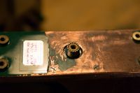
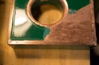
Prying the first copper shield off was a whole evening job. Notice that the two shields are not connected in the through-hole, there is only a tiny narrow slot for the magnetic field to enter the CT.
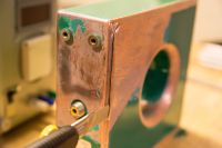
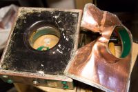
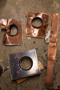
Carefully chipping the epoxy off was a job that took some evenings week upon week, it was over a long period.
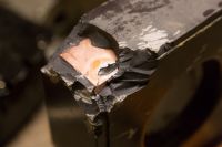
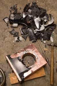
After I had removed the inner copper shielding I lost all hope and interest when there was just another layer of epoxy and this time chipping it off was not an option, now there is components and a ?brittle? core involved. I left it on a shelf for a long time.
Last week I found a large pan on the scrap yard and thought, I will try to cook it and see what that does to the epoxy. Just add salt and pepper for a tasty transformer soup.
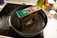
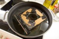
The last remaining copper part with connector in it came loose in first boiling run and a cable revealed where the series resistor was located. Carefully removing the softened epoxy, the series resistor came apart in tiny pieces and from the look of it, it was once warm, maybe too warm. This was however also the only visible damage I found.
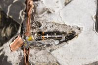
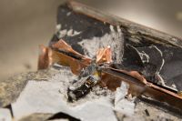
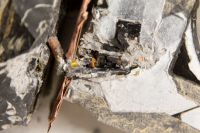
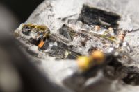
Connector got out in the free
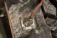
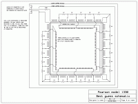
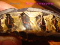
On the inside of the through-hole, which by the way was only accessible for electromagnetic waves through a thin 2-3 mm wide slot between the shieldings from each side of it, there was another weird coil of 5-6 hair thin wires, wave shaped, in parallel on a wide piece of tape, tapped for each 30mm with a gold wire into the distributed load resistors on the regular large coil. See schematic.
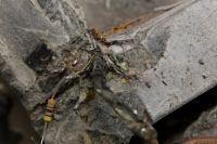
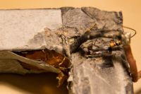
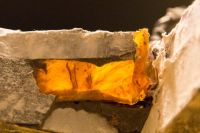
The thin wave-shaped wires should be visible from these two different angles
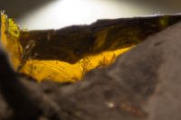
Schematic made from my best guess on how its connected, number of distributed load resistors it not accurate.
As you can see, I tried replacing the 39R series resistor, identified by the rings it left in the epoxy, and not with a great result, DC resistance is still far from specification.
This way the money was not all a waste. End of story, so far. February 2016.
Re: Pearson current monitor model 1330 teardown (100kA)
Dr. H., Fri Feb 26 2016, 06:23AM
Big BIG thumbs up for the Perseverance Mads. Very interesting info indeed.
Thanks for shearing.
Cheers
Dr. H., Fri Feb 26 2016, 06:23AM
Big BIG thumbs up for the Perseverance Mads. Very interesting info indeed.
Thanks for shearing.
Cheers
Re: Pearson current monitor model 1330 teardown (100kA)
Chris_Knight, Fri Feb 26 2016, 07:27AM
Have to commend you for sticking through so long. My curiosity would have met its limits long ago!
Chris_Knight, Fri Feb 26 2016, 07:27AM
Have to commend you for sticking through so long. My curiosity would have met its limits long ago!
Re: Pearson current monitor model 1330 teardown (100kA)
Finn Hammer, Fri Feb 26 2016, 11:38AM
Great autopsy report. I do , however, find it safe to assume, that the magnetic field passes trough the complete structure (-the core) whereas the copper shielding serves to shield against electrical fields.
But I may be wrong.
Cheers, Finn Hammer
Finn Hammer, Fri Feb 26 2016, 11:38AM
Mads Barnkob wrote ...
snip
Prying the first copper shield off was a whole evening job. Notice that the two shields are not connected in the through-hole, there is only a tiny narrow slot for the magnetic field to enter the CT.
snip
Prying the first copper shield off was a whole evening job. Notice that the two shields are not connected in the through-hole, there is only a tiny narrow slot for the magnetic field to enter the CT.
Great autopsy report. I do , however, find it safe to assume, that the magnetic field passes trough the complete structure (-the core) whereas the copper shielding serves to shield against electrical fields.
But I may be wrong.
Cheers, Finn Hammer
Re: Pearson current monitor model 1330 teardown (100kA)
Dr. H., Fri Feb 26 2016, 11:48AM
My guess is that this little gap is there to prevent the shielding from acting as a shorted turn and that the magnetic field, as Finn sad, will pass through the copper shield.
Dr. H., Fri Feb 26 2016, 11:48AM
My guess is that this little gap is there to prevent the shielding from acting as a shorted turn and that the magnetic field, as Finn sad, will pass through the copper shield.
Re: Pearson current monitor model 1330 teardown (100kA)
Finn Hammer, Fri Feb 26 2016, 12:00PM
Sorry to double post, but I couldn´t add pictures in the edit mode, and they are on another pc.
I took a 110 apart some 10 years ago, and it had a different distribution of balancing resistors:
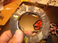
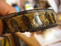
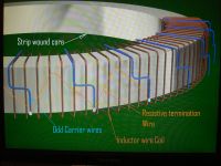
I thought it would be so difficult to explain how the wires went, so I rendered it in 3DS to try and make it clear.
Cheers, Finn Hammer
Finn Hammer, Fri Feb 26 2016, 12:00PM
Sorry to double post, but I couldn´t add pictures in the edit mode, and they are on another pc.
I took a 110 apart some 10 years ago, and it had a different distribution of balancing resistors:


I thought it would be so difficult to explain how the wires went, so I rendered it in 3DS to try and make it clear.
Cheers, Finn Hammer
Re: Pearson current monitor model 1330 teardown (100kA)
Mads Barnkob, Fri Feb 26 2016, 09:26PM
You are of course right, what I meant was shielding from other than what is passing through the hole. There is also a difference, outer shield is not grounded to the CT output, inner shield is.
It is interesting to see that the smaller models only uses the resistive hair thin wave shaped wire and not distributed resistors as in the large. Or interesting that the large uses both, yours only had 1 wire, mine got 5-6 in parallel, maybe it was just not enough.
Did it have any series resistor near the connector?
Mads Barnkob, Fri Feb 26 2016, 09:26PM
Finn Hammer wrote ...
Great autopsy report. I do , however, find it safe to assume, that the magnetic field passes trough the complete structure (-the core) whereas the copper shielding serves to shield against electrical fields.
But I may be wrong.
Cheers, Finn Hammer
Mads Barnkob wrote ...
snip
Prying the first copper shield off was a whole evening job. Notice that the two shields are not connected in the through-hole, there is only a tiny narrow slot for the magnetic field to enter the CT.
snip
Prying the first copper shield off was a whole evening job. Notice that the two shields are not connected in the through-hole, there is only a tiny narrow slot for the magnetic field to enter the CT.
Great autopsy report. I do , however, find it safe to assume, that the magnetic field passes trough the complete structure (-the core) whereas the copper shielding serves to shield against electrical fields.
But I may be wrong.
Cheers, Finn Hammer
You are of course right, what I meant was shielding from other than what is passing through the hole. There is also a difference, outer shield is not grounded to the CT output, inner shield is.
It is interesting to see that the smaller models only uses the resistive hair thin wave shaped wire and not distributed resistors as in the large. Or interesting that the large uses both, yours only had 1 wire, mine got 5-6 in parallel, maybe it was just not enough.
Did it have any series resistor near the connector?
Re: Pearson current monitor model 1330 teardown (100kA)
Finn Hammer, Sun Feb 28 2016, 10:36AM
No resistors in the 110, and frankly, I felt that it looked a bit cheap with the ordinary resistors, in the 1330 of yours, but perhaps not.
I often have been thinking about making a homemade current monitor with distributed resistors on a pcb, where each turn has 1/4 of the winding as a track on the pcb, then the other 3/4 of each winding as U-shaped loops soldered in. Then the resistors could be surface mount types soldered on the pcb too. Not sure it would make any difference for our applications, though.
Cheers, Finn Hammer
Re: Pearson current monitor model 1330 teardown (100kA)
Mads Barnkob, Sun Feb 28 2016, 12:20PM
I did not crush any of the 1K, but the 39R was carbon composite.
We are missing something about the different terminations, the thin wave-shaped wires was only for each 30 mm, the 1K resistors was for each 5-10 mm,
Did you makes any notice of the core being made of anything special or was it just a large ferrite ring core? The 1330 is square, as you can see I knocked one of the inner corner filings out. It has a metal band all around it on the outer side to keep it all together.
When we talk home made current transformers, it always boils down to calibration issues and that is one reason to use commercial CTs. But still interesting idea about the core being soldered to the PCB with all the clamp shaped wires and sure makes it easier to solder in distributed load resistors.
Re: Pearson current monitor model 1330 teardown (100kA)
Finn Hammer, Sun Feb 28 2016, 05:14PM
The core was a strip wound, very thin lamination strip, wound from something looking rather funky, I guess high nickel or cobalt content, from the shinyness of it.
Calibration of a Pearson is a joke, as calibration is same price as a new one, and guesss why that is so.
My guess is, they toss the old one, and ship a new unit.
Cheers, Finn Hammer
Re: Pearson current monitor model 1330 teardown (100kA)
Mads Barnkob, Sun Feb 28 2016, 08:45PM
Yep, there is nothing to calibrate, you can only check its calibration. That is what I meant, we hope that the 2nd hand commercial CTs are still up to specifications and then we, in some way, have a calibrated monitor :)
The 1330 is properly made of the same strip material, just with sharper corners.
Mads Barnkob, Sun Feb 28 2016, 08:45PM
Finn Hammer wrote ...
The core was a strip wound, very thin lamination strip, wound from something looking rather funky, I guess high nickel or cobalt content, from the shinyness of it.
Calibration of a Pearson is a joke, as calibration is same price as a new one, and guesss why that is so.
My guess is, they toss the old one, and ship a new unit.
Cheers, Finn Hammer
Yep, there is nothing to calibrate, you can only check its calibration. That is what I meant, we hope that the 2nd hand commercial CTs are still up to specifications and then we, in some way, have a calibrated monitor :)
The 1330 is properly made of the same strip material, just with sharper corners.
Re: Pearson current monitor model 1330 teardown (100kA)
Wolfram, Sun Feb 28 2016, 11:28PM
Excellent thread! I've always wondered what kind of magic they put under the green paint to get their famously good performance.
On a related note, I've found a good description of a DIY wideband CT with very usable specifications. The description comes from the book "Inductors and Transformers for Power Electronics" by Valchev and Van den Bossche. The page in question is openly available on Google books , and I've reproduced it here in good faith.
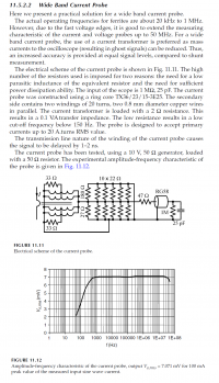
Note that the resistor loading half of the secondary should be 330 ohms, not 33, this is stated in the errata for the book.
Wolfram, Sun Feb 28 2016, 11:28PM
Excellent thread! I've always wondered what kind of magic they put under the green paint to get their famously good performance.
On a related note, I've found a good description of a DIY wideband CT with very usable specifications. The description comes from the book "Inductors and Transformers for Power Electronics" by Valchev and Van den Bossche. The page in question is openly available on Google books
 , and I've reproduced it here in good faith.
Note that the resistor loading half of the secondary should be 330 ohms, not 33, this is stated in the errata for the book.
Re: Pearson current monitor model 1330 teardown (100kA)
Mads Barnkob, Mon Feb 29 2016, 09:19AM
I have a few pages from some journal, forgot where I have it from. I thought some of the ideas described inhere with multiply smaller cores in parallel and opposite direction coils etc was some I would see in the 1330. Turned out not to, but here is the 4 pages PDF for your entertainment.
]high-frequency__current__transformer.pdf[/file]
Re: Pearson current monitor model 1330 teardown (100kA)
DerAlbi, Mon Feb 29 2016, 10:45AM
DerAlbi, Mon Feb 29 2016, 10:45AM
Note that the resistor loading half of the secondary should be 330 ohms, not 33, this is stated in the errata for the book.May i ask, just for curiosity, what this half load does in the first place??
Re: Pearson current monitor model 1330 teardown (100kA)
johnf, Tue Mar 01 2016, 08:54AM
It is used as a Q killer
and it will remove any resonances from stray "C" in the windings
johnf, Tue Mar 01 2016, 08:54AM
It is used as a Q killer
and it will remove any resonances from stray "C" in the windings
Re: Pearson current monitor model 1330 teardown (100kA)
klugesmith, Tue Mar 01 2016, 03:45PM
This thread stands out from the chaff. Thanks, Mads.
And thanks to John for sharing wisdom about the damping art.
Makes me want to test my matched pair of Pearson CT's. They have about the same size and color as the one autopsied above. A lucky flea market find a few years ago, and never yet used by me.
[edit] As requested by a moderator, I moved my off-track comment about broadband Current Viewing Resistors to a new thread. Now it's Albi's turn.
Re: Pearson current monitor model 1330 teardown (100kA)
Bert, Sat Apr 30 2016, 05:18AM
Thank you for your patience in tearing apart the large CT and for sharing the photos with us!
Dr. Paul Pearson's original 1964 patent appears to shed a fair amount of light on the theory and early construction of a similar double-shielded large wideband CT.
A more recent Pearson Electronics patent (from 1998) appears to cover some design approaches used in their smaller toroidal CT's.
A relatively recent paper discusses differences between core materials (strip wound Si steel, Ni-Fe alloys, and nanocrystalline iron allloys), remenence effects and mitigation, and frequency effects of core materials in wideband CT's.
Finally, there's a very interesting paper from CERN that compares performance between a Pearson 7546, a Stangenes 3-0.002, and a PEM CWT 150XB Rogowski coil versus a precision current shunt resistor. All three CT's show excellent results.
Bert, Sat Apr 30 2016, 05:18AM
Thank you for your patience in tearing apart the large CT and for sharing the photos with us!
Dr. Paul Pearson's original 1964 patent appears to shed a fair amount of light on the theory and early construction of a similar double-shielded large wideband CT.

A more recent Pearson Electronics patent (from 1998) appears to cover some design approaches used in their smaller toroidal CT's.

A relatively recent paper discusses differences between core materials (strip wound Si steel, Ni-Fe alloys, and nanocrystalline iron allloys), remenence effects and mitigation, and frequency effects of core materials in wideband CT's.

Finally, there's a very interesting paper from CERN that compares performance between a Pearson 7546, a Stangenes 3-0.002, and a PEM CWT 150XB Rogowski coil versus a precision current shunt resistor. All three CT's show excellent results.

Re: Pearson current monitor model 1330 teardown (100kA)
Mads Barnkob, Mon May 02 2016, 06:34AM
Thank you Bert, the first link to the 1964 patent really sheds some light over it, and also confirms the schematic I drew from disassembling.
The patent describes the segmented construction pretty well in a short chapter.
Mads Barnkob, Mon May 02 2016, 06:34AM
Thank you Bert, the first link to the 1964 patent really sheds some light over it, and also confirms the schematic I drew from disassembling.
The patent describes the segmented construction pretty well in a short chapter.
In making a transformer which will monitor high currents, it is necessary to make the value of the load resistance relatively low. If the resistance wire has to traverse the same length for a very high current model as for a low current model, the ratio of resistance to inductance becomes appreciably worse. To combat this problem, the load resistance is broken up into short lengths as shown in FIGURE 11 in which the resistance portions 14a are separated by relatively wide, high conductance portions 15. The individual resistors are short and possibly thick and wide, thus lowering the inductance of the individual resistance well below the inductance of the resistance if it had a length equal to the length per section. The connecting wires are secured to the ends of the resistance portions 14a. Wide copper strips may be used for the high conductance portions. The resistance portions are connected in shunt with corresponding .coil sections 13a.
Re: Pearson current monitor model 1330 teardown (100kA)
Hydron, Wed Aug 10 2016, 05:26PM
More info that may be of use to understand the construction of these:
My measurements of the exposed parts of a 3525 split CT (datasheet: http://www.pearsonelectronics.com/pdf/3525.pdf):
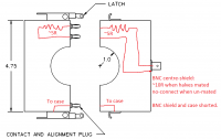
Measurements support the theory of distributed parallel termination throughout the coil, either with no series resistor (coil DC resistance is ~10R), distributed series resistance, or a lumped series resistance (minimum of 2 lumped parts, half on each side of split).
Also could see the location of the anti-shorted-turn split line in the case - it's between the centre bore and the hole in one of the top plates.
Have done a quick check against a pearson 4100, see 10k-10M freq sweep and test setup below (50R termination makes little difference, sweep plot is without it):
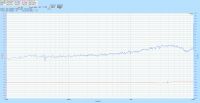
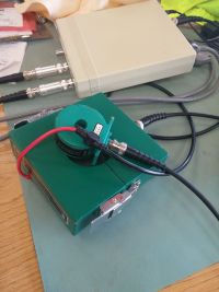
The 4100 measures a dead short across the BNC - obviously there is no series resistance being used with this 1V/A unit, only the winding (dead short at DC) and a parallel termination.
Edit: it appears that the phase shift at high frequencies is affected significantly by the position of the wire within the core. Best is with it centred - worth taking care to do this if operating above 0.1x of rated 3dB frequency.
Hydron, Wed Aug 10 2016, 05:26PM
More info that may be of use to understand the construction of these:
My measurements of the exposed parts of a 3525 split CT (datasheet: http://www.pearsonelectronics.com/pdf/3525.pdf):

Measurements support the theory of distributed parallel termination throughout the coil, either with no series resistor (coil DC resistance is ~10R), distributed series resistance, or a lumped series resistance (minimum of 2 lumped parts, half on each side of split).
Also could see the location of the anti-shorted-turn split line in the case - it's between the centre bore and the hole in one of the top plates.
Have done a quick check against a pearson 4100, see 10k-10M freq sweep and test setup below (50R termination makes little difference, sweep plot is without it):


The 4100 measures a dead short across the BNC - obviously there is no series resistance being used with this 1V/A unit, only the winding (dead short at DC) and a parallel termination.
Edit: it appears that the phase shift at high frequencies is affected significantly by the position of the wire within the core. Best is with it centred - worth taking care to do this if operating above 0.1x of rated 3dB frequency.
Print this page