Need advice on this slayer circuit
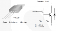
jdub1581hv, Wed Jul 22 2015, 02:39PMSo I have been using this slayer circuit:
2- TIP3055 paralleled
It works well and quite well with my setup. The transistors only heat up when long duration arcs are pulled.
Gives my coil about 1" bushy ball like outbreak.
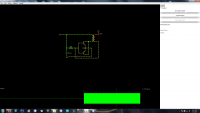
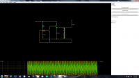
So I started playing with my circuit simulator (I know it doesn't always work in the real world) modifying the circuit.
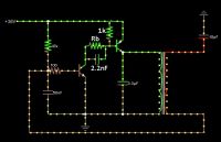
I was hoping if anyone can tell me if this looks right (last image).. Cap and ground on secondary represent the top load.
I also set the transformer values as close to mine as possible including coupling at 0.2.
Basically the same as Image 1, with the added PNP, and a Cap across the primary.
Was hoping for review Before I build this and possibly blow up my transistors.
Transistors I have for this are TIP3055, TIP42G .

Re: Need advice on this slayer circuit
jdub1581hv, Sat Jul 25 2015, 03:19AM
No one? nothing?
jdub1581hv, Sat Jul 25 2015, 03:19AM
No one? nothing?
Re: Need advice on this slayer circuit
Antonio, Sat Jul 25 2015, 02:07PM
The second will probably just destroy the PNP transistor. Test it with a current-limiting resistor in series with the primary.
Antonio, Sat Jul 25 2015, 02:07PM
The second will probably just destroy the PNP transistor. Test it with a current-limiting resistor in series with the primary.
Re: Need advice on this slayer circuit
mister_rf, Sat Jul 25 2015, 06:51PM
What Antonio is saying is you need to have a current limiting resistor in front of the base terminal on the transistor, which does exactly what its name describes, limits the current.
The base-emitter junction acts like any silicon diode (it’s the 'NP' part of the PNP transistor). For current to flow through the junction the base must be about 0.6V higher than the emitter.
The value of base resistor sets the size of base current. As the voltage drop across the transistor will remain at 0.6-0.8V we can work out the size resistor we would need quite easily.
R = (Vin - Vdrop)/I,
I = the base current that it can take, to force saturation
Vdrop = the voltage drop from the base to the emitter
Vin = the supply that is going into base
Also need to look at the hfe of the transistor so see if it will be able to give you the amount of current is needed.
In the attached picture Rb is simply a label and may have different values in different circuits. Let’s say Rb = 220 ohms up to 1k.

Re: Need advice on this slayer circuit
jdub1581hv, Sat Jul 25 2015, 09:50PM
Thanks guys! My buddy I usually go to for help is out of town for a few months for work.
He actually got me into the electronics side of electricity.. lol.
I knew there would be a problem with the PNP, as in the sim the tank cap was reaching towards the sky in terms of wattage.
So for "Rb" say I put a 220ohm followed by a 1k pot this should allow for some mediocre tuning?
I'm using a 9v battery to check my circuits so nothing goes boom.
I also have a few TIP107 pnp darlingtons with 1k to 20k hfe
8amp tolerance at collector and 1a at base..
I'll try these as well, and post an update.
Now I just need to get a good psu. as my 75va 22v xfmr gets stressed a bit..
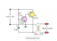
This was where I took the idea from: (mixing the two)


Print this page
