How do I stop the ringing in my Gate Drive Circuit
Cool Dude Clem, Mon Jul 06 2015, 12:11AMHi there, it's been a while since I've been here but anyway. I'm trying to make this tesla coil.

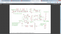
You may have come across this yourself, well I thought I'd start by building the gate drive circuit to make sure that works and well, it kinda doesn't. I tied pin 3 of both UCC chips high so they would both be enabled, and fed a high frequency squarewave into pin 2 on both the chips, and I connected the Gate Drive Transformer to my oscilloscope. and instead of something that resembles a squarewave, I get this:

So what can I do about this? I even get this nasty distortion at the primary of the gate drive transformer as-well.
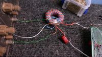
This is the transformer itself.

I the core is from a car audio amplifier board, each coil is 15 turns, and the wire I used for each coil is twisted pair of insulated single strand wire. I was so sure this would work, and now all that careful planning down the drain!
Re: How do I stop the ringing in my Gate Drive Circuit
Sulaiman, Mon Jul 06 2015, 12:22AM
try loading each secondary winding with 4.7nF (input capacitance of IRFP369)
in series with 5 Ohms (gate resistor per circuit diagram).
This will simulate actual conditions and give a better representation of what will happen in the actual circuit
Sulaiman, Mon Jul 06 2015, 12:22AM
try loading each secondary winding with 4.7nF (input capacitance of IRFP369)
in series with 5 Ohms (gate resistor per circuit diagram).
This will simulate actual conditions and give a better representation of what will happen in the actual circuit
Re: How do I stop the ringing in my Gate Drive Circuit
Sigurthr, Mon Jul 06 2015, 12:46AM
Also you should bifiliarly twist the termination leads of your GDT to minimize stray inductances. Keep leads short as possible, and keep untwisted lengths even shorter.
Sigurthr, Mon Jul 06 2015, 12:46AM
Also you should bifiliarly twist the termination leads of your GDT to minimize stray inductances. Keep leads short as possible, and keep untwisted lengths even shorter.
Re: How do I stop the ringing in my Gate Drive Circuit
zzz_julian_zzz, Mon Jul 06 2015, 05:30AM
Scope both of the UCC chip's output(with respect to ground) first without the DC blocking cap and GDT. Check if the ringing is already there. You should be able to see clean square waves (rail-to-rail)
zzz_julian_zzz, Mon Jul 06 2015, 05:30AM
Scope both of the UCC chip's output(with respect to ground) first without the DC blocking cap and GDT. Check if the ringing is already there. You should be able to see clean square waves (rail-to-rail)
Re: How do I stop the ringing in my Gate Drive Circuit
Goodchild, Mon Jul 06 2015, 02:12PM
As with what others have said you have a combination of two issues, loading and damping. The ringing is a result of oscillation between the leakage inductance of the secondary winding and the unloaded capacitance.
You will want to "load" the output as it would be in circuit. The best load can be the gate of the transistor you plan to drive. After it has the correct capacitive load on the output you may need to add some gate resistance in series to damp out the rest of the oscillations to bring the system to a "critically damped" point of operation.
Re: How do I stop the ringing in my Gate Drive Circuit
mister_rf, Mon Jul 06 2015, 07:49PM
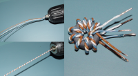
The attached picture will make this clearer (but in the picture the toroid/number of turns are not on scale, just to illustrate how to). The tri-filar was twisted together using a hand drill.

mister_rf, Mon Jul 06 2015, 07:49PM
Cool Dude Clem wrote ...
This is the transformer itself.

I the core is from a car audio amplifier board, each coil is 15 turns, and the wire I used for each coil is twisted pair of insulated single strand wire. I was so sure this would work, and now all that careful planning down the drain!
For the lowest leakage you may use a tri-filar wire.This is the transformer itself.

I the core is from a car audio amplifier board, each coil is 15 turns, and the wire I used for each coil is twisted pair of insulated single strand wire. I was so sure this would work, and now all that careful planning down the drain!
The attached picture will make this clearer (but in the picture the toroid/number of turns are not on scale, just to illustrate how to). The tri-filar was twisted together using a hand drill.


Re: How do I stop the ringing in my Gate Drive Circuit
Cool Dude Clem, Mon Jul 06 2015, 09:05PM
Ok thanks for all that. I checked at the UCC's output without the transformer connected and there is a little ringing there, but it's not as bad as what I get out from the transformer. However when I do connect the transformer, the Ringing at the chip's output get's worse, it looks just like what comes out of the transformer.
Also I investigated putting a load on the transformer, so I tried with a spare irf840 I have laying around that I'm not going to use so I'm not to worried if i kill it with too much gate current, I connecte3d that to the transformer in series with a 5 ohm resistor, then I scoped the gate voltage and the ringing was almost gone, so I tried with a 18 ohm resistor and the waveform was better, but had quite a bit of "ramping", even with the 5 ohm resistor there's about the same amount of ramping.
So, about making a better transformer ... Do I only need 1 strand of wire for each coil on the transformer then I just twist them round each other before I wind them on to the transformer, like in the picture? I thought each coil had to be made from 2 or more strands of wire twisted together.
Re: How do I stop the ringing in my Gate Drive Circuit
Dr. Slack, Mon Jul 06 2015, 10:52PM
Ah! That explains the unusual winding of the first GDT shown in your photo. While there are times when a transformer winding should be several multiple wires all connected in parallel *, in a GDT is not one of them. Twisting the primary with all the secondaries reduces the leakage inductance to the minimum possible, our attempt to get all the windings taking the same path through the core. Resistive losses are more or less irrelevant, especially as we are adding extra R in series with the output. One thin conductor per coil is what's needed, primary twisted with all secondaries before winding.
* For current carrying capacity, when you can't get thick wire, or thick wire is too stiff to handle. Or for RF losses when minimum loss is crucial, so in very high power transformers or in high Q filters, and then we use Litz wire, which is many tens or even >100 strands.
Dr. Slack, Mon Jul 06 2015, 10:52PM
Cool Dude Clem wrote ...
I thought each coil had to be made from 2 or more strands of wire twisted together.
I thought each coil had to be made from 2 or more strands of wire twisted together.
Ah! That explains the unusual winding of the first GDT shown in your photo. While there are times when a transformer winding should be several multiple wires all connected in parallel *, in a GDT is not one of them. Twisting the primary with all the secondaries reduces the leakage inductance to the minimum possible, our attempt to get all the windings taking the same path through the core. Resistive losses are more or less irrelevant, especially as we are adding extra R in series with the output. One thin conductor per coil is what's needed, primary twisted with all secondaries before winding.
* For current carrying capacity, when you can't get thick wire, or thick wire is too stiff to handle. Or for RF losses when minimum loss is crucial, so in very high power transformers or in high Q filters, and then we use Litz wire, which is many tens or even >100 strands.
Re: How do I stop the ringing in my Gate Drive Circuit
Sigurthr, Tue Jul 07 2015, 12:21AM
Sounds like in addition to the winding issues you have an under-decoupled power supply from the amplifier section (UCC chips). You need to decouple power ICs because of the high transient currents demanded and the on-board inductance of traces. For my own boards I place a very large electrolytic on board supplying all rails before regulators, and then smaller (~100uF) electrolytics on the regulated rails. Then very near the power chips themselves I put low value electrolytics (~10uF), and either ceramic or film/foil poly decoupling caps (0.1uF) right at the chips power pins.
Sigurthr, Tue Jul 07 2015, 12:21AM
Cool Dude Clem wrote ...
Ok thanks for all that. I checked at the UCC's output without the transformer connected and there is a little ringing there, but it's not as bad as what I get out from the transformer. However when I do connect the transformer, the Ringing at the chip's output get's worse, it looks just like what comes out of the transformer.
Also I investigated putting a load on the transformer, so I tried with a spare irf840 I have laying around that I'm not going to use so I'm not to worried if i kill it with too much gate current, I connecte3d that to the transformer in series with a 5 ohm resistor, then I scoped the gate voltage and the ringing was almost gone, so I tried with a 18 ohm resistor and the waveform was better, but had quite a bit of "ramping", even with the 5 ohm resistor there's about the same amount of ramping.
So, about making a better transformer ... Do I only need 1 strand of wire for each coil on the transformer then I just twist them round each other before I wind them on to the transformer, like in the picture? I thought each coil had to be made from 2 or more strands of wire twisted together.
Sounds like in addition to the winding issues you have an under-decoupled power supply from the amplifier section (UCC chips). You need to decouple power ICs because of the high transient currents demanded and the on-board inductance of traces. For my own boards I place a very large electrolytic on board supplying all rails before regulators, and then smaller (~100uF) electrolytics on the regulated rails. Then very near the power chips themselves I put low value electrolytics (~10uF), and either ceramic or film/foil poly decoupling caps (0.1uF) right at the chips power pins.
Print this page