G-E waveform
zzz_julian_zzz, Sat Feb 07 2015, 04:21PMHi,
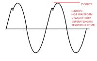
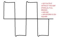
I am still building my QCW bridge, just noticed something strange in the Gate Emitter Voltage waveform on my IGBT (parallel, full bridge, separated resistor - 10 ohms), when Bridge (TO-247 IGBTs) is connected to the GDTs, the output waveforms coming from 2 GDTs (G-E) are going "CURVY" @ 420 khz , 10ms ON TIME, not unlike when the bridge is disconnected from GDTs, waveforms are square - so are ok.
Any idea why this is happening ? and should I really need to be worried of this gate waveform or this is normal?
Maybe 10 ohms is a bit high that's why the waves are slow (curvy) ? any thought is highly appreciated, thank you.


Re: G-E waveform
johnf, Sat Feb 07 2015, 06:40PM
I think this is caused by the gate capacitance of your IGBT.
To prove it lower the gate resistor to 3.3 ohms and see if the wave form steepens up
johnf, Sat Feb 07 2015, 06:40PM
I think this is caused by the gate capacitance of your IGBT.
To prove it lower the gate resistor to 3.3 ohms and see if the wave form steepens up
Re: G-E waveform
loneoceans, Sat Feb 07 2015, 06:59PM
What transistors are you using? I use 15 ohms on each of my TO247 IGBTs (60N60 or 50B60) and they do fine at 400kHz. What I expect to see is that the gate voltage (from 0) should rise up quite smoothly to about 8-10V, plataeu for a while, and then shoot up to 24V or whatever your gate drive voltage is. But when you zoom out it should look square.
Are you measuring it properly? Make sure your bridge rails are isolated when measuring with a scope.
Re: G-E waveform
zzz_julian_zzz, Sun Feb 08 2015, 12:20AM
I think I'm isolated, because the 240v coming to my scope came from an isolation transformer 1:1.. so the bridge (i think) would be isolated. I use this transistor STGW60H65DFB. I don't see any square waveforms... (If the test signal (from my frequency generator is at 100khz, it is perfectly square, but when I try increasing the frequency up, 200khz-300khz, the "square corners" wave turns to curve until I see an almost sine wave G-E signal. I somehow see that 10v plateau you were saying, it is as if the wave stops for a moment and then spike up.
zzz_julian_zzz, Sun Feb 08 2015, 12:20AM
loneoceans wrote ...
What transistors are you using? I use 15 ohms on each of my TO247 IGBTs (60N60 or 50B60) and they do fine at 400kHz. What I expect to see is that the gate voltage (from 0) should rise up quite smoothly to about 8-10V, plataeu for a while, and then shoot up to 24V or whatever your gate drive voltage is. But when you zoom out it should look square.
Are you measuring it properly? Make sure your bridge rails are isolated when measuring with a scope.
I think I'm isolated, because the 240v coming to my scope came from an isolation transformer 1:1.. so the bridge (i think) would be isolated. I use this transistor STGW60H65DFB. I don't see any square waveforms... (If the test signal (from my frequency generator is at 100khz, it is perfectly square, but when I try increasing the frequency up, 200khz-300khz, the "square corners" wave turns to curve until I see an almost sine wave G-E signal. I somehow see that 10v plateau you were saying, it is as if the wave stops for a moment and then spike up.
Re: G-E waveform
Kizmo, Sun Feb 08 2015, 11:13AM
It sounds like you simply run out of drive power. To verify you could try to drive just 2 or 4 transistors and see if it improves things
Kizmo, Sun Feb 08 2015, 11:13AM
It sounds like you simply run out of drive power. To verify you could try to drive just 2 or 4 transistors and see if it improves things
Re: G-E waveform
zzz_julian_zzz, Sun Feb 08 2015, 03:55PM
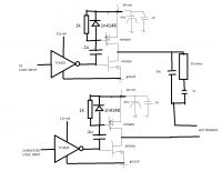
I'm afraid this could be the problem. I could try reducing the driven transistors in the next few days, and see the G-E waveform. Assuming the waveform improves(and i believe it will, because at no load transistors, even test frequency at 500khz waveforms in my GDT secondaries are clean square), what things can I do to "counter" the lacking driver power problem?
My current scheme looks like this:
Thanks in advance.

EDIT: MOSFETS were swapped in the drawing. P channel on the high, N channel at the low. sorry.
zzz_julian_zzz, Sun Feb 08 2015, 03:55PM
Kizmo wrote ...
It sounds like you simply run out of drive power. To verify you could try to drive just 2 or 4 transistors and see if it improves things
It sounds like you simply run out of drive power. To verify you could try to drive just 2 or 4 transistors and see if it improves things
I'm afraid this could be the problem. I could try reducing the driven transistors in the next few days, and see the G-E waveform. Assuming the waveform improves(and i believe it will, because at no load transistors, even test frequency at 500khz waveforms in my GDT secondaries are clean square), what things can I do to "counter" the lacking driver power problem?
My current scheme looks like this:
Thanks in advance.

EDIT: MOSFETS were swapped in the drawing. P channel on the high, N channel at the low. sorry.
Print this page