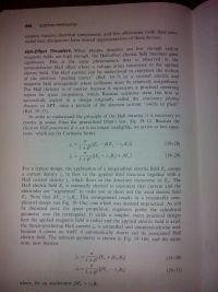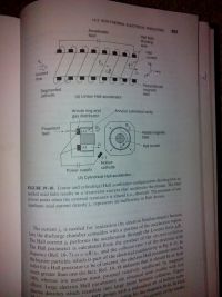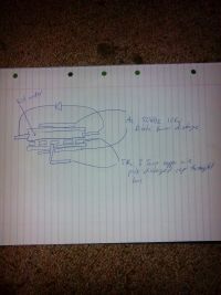
Submarine engine
Andy, Mon Jan 05 2015, 08:51AMI think have have done enought thoery on the engine, im just starting to build it, the first stage is build a hv cap, second is get the magntics and make the u shaped housen.
The engine is a side path for a submarine that I plan on building, will update the post with more of the theroy docs.
The engine is powered by a electric current throught salt water, with magntics to convert the water to velocity, and then turn a turbine.
Some pics
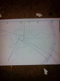
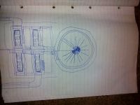
Re: Submarine engine
Sulaiman, Mon Jan 05 2015, 09:10AM
What is the purpose of the turbine/propeller?
Wouldn't it be better to use a 'normal' Magnetohydrodynamic drive arrangement?
Sulaiman, Mon Jan 05 2015, 09:10AM
What is the purpose of the turbine/propeller?
Wouldn't it be better to use a 'normal' Magnetohydrodynamic drive arrangement?

Re: Submarine engine
Andy, Mon Jan 05 2015, 09:21AM
Hi Suliaman
The pressure of the exhust is so low compared to the surronds that it would be massivly ineffecient.
A 30J pulse in 1uS should create enought hydrogen and oxygen to fill a space 1*4*50cm tube in that pulse, if most of it is gas copared to 15psi per ten meter depth.
Re: Submarine engine
Andy, Wed Jan 07 2015, 06:48AM
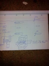
Would this design work, using just the jet. Trying to make a really smale pipe and accerlate it up fast, the get the surronds to speed up as this goes throught it, thoughs.
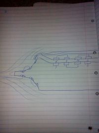
Andy, Wed Jan 07 2015, 06:48AM
Would this design work, using just the jet. Trying to make a really smale pipe and accerlate it up fast, the get the surronds to speed up as this goes throught it, thoughs.

Re: Submarine engine
Andy, Thu Jan 08 2015, 11:33PM
Got a protype up and running, tryed 24 @ 48 volt with a 10 ohm resistor, the velocity would have workedout to about 1 m /1 min
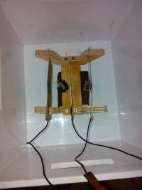
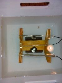
Andy, Thu Jan 08 2015, 11:33PM
Got a protype up and running, tryed 24 @ 48 volt with a 10 ohm resistor, the velocity would have workedout to about 1 m /1 min


Re: Submarine engine
Andy, Fri Jan 09 2015, 10:03PM
Running the thing with a car battery charger, added two more mags, the velocity is about one meter in ten seconds.
Below is a module that I think will build, just got to double check some stuff.
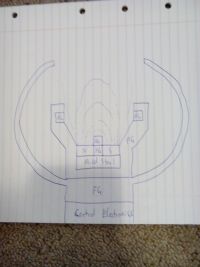
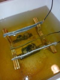
Andy, Fri Jan 09 2015, 10:03PM
Running the thing with a car battery charger, added two more mags, the velocity is about one meter in ten seconds.
Below is a module that I think will build, just got to double check some stuff.


Re: Submarine engine
Sulaiman, Fri Jan 09 2015, 10:45PM
I'd expect some 'leakage' current to/through the magnets
(outer terminal | fluid | magnet | fluid | inner terminal )
electrical current flowing along magnetic field lines does no work,
try insulating the magnets from the liquid,
may be more efficient.
Sulaiman, Fri Jan 09 2015, 10:45PM
I'd expect some 'leakage' current to/through the magnets
(outer terminal | fluid | magnet | fluid | inner terminal )
electrical current flowing along magnetic field lines does no work,
try insulating the magnets from the liquid,
may be more efficient.
Re: Submarine engine
Andy, Sat Jan 10 2015, 03:03AM
Thanks Sulaiman, tryed to insulate the mags, but made less, im guessing the current sleed across the top, make it 90 degree angles.
Also tryed useing Ti instead of steel, moving the plates closer made more speed.
Im guessing the design is floured, should have the mags in close proxmity to make the path short, and maybe Al and Ti plates as that with both seems to increase the power.
Plan B, following a more well know design
This is the setup from above
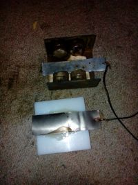
This is the second design, It has 4 mags point down then Mild steel directs the field to the left and the other 4 mags point it up.
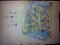
[Edit: Merged triple post]
Andy, Sat Jan 10 2015, 03:03AM
Thanks Sulaiman, tryed to insulate the mags, but made less, im guessing the current sleed across the top, make it 90 degree angles.
Also tryed useing Ti instead of steel, moving the plates closer made more speed.
Im guessing the design is floured, should have the mags in close proxmity to make the path short, and maybe Al and Ti plates as that with both seems to increase the power.
Plan B, following a more well know design
This is the setup from above

This is the second design, It has 4 mags point down then Mild steel directs the field to the left and the other 4 mags point it up.

[Edit: Merged triple post]
Re: Submarine engine
Andy, Sun Jan 11 2015, 05:27PM
Tested using more reactive platrs, the source is still a 12v,2amp battery charge, next test will be trying to increase the source power
Messured the resistance of the device and are getting 14.5ohms
Below is a 24volt 2amp source
Below is a 36 volt 2 amp source
Below is a 60. 4.5. Volt. Amp throw device, with a 30uF smoothing cap for the ac recifered parts, the resisance of the mhd drive is 14.5 ohms messured by a voltage dividerr. ,R2=10ohm, vin= 12 vout=4.90
Re: Submarine engine
Andy, Sat Jan 24 2015, 07:53AM
Been spending sometime work out a way to get high volts with a high frequency, trying to find a way that will injuice large current throught the water as that has reached a bottle neck.
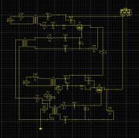
The below circuit is driven from main voltage and frequncy, with a h bridge setup to slice the ac up.
For isolation between stages are 30kv 100nf cap network on both plus and minus.
The zeners are rated for 10 volt, the transfomers are pulse types with the values taken from the datasheet, one is 50hz 0.8ohm the other 60khz at 80mohm.
The parts for this are quite cheap to muck around building it, in a while should have a prototype built and tested.
If anything is wrong with the circuit, wouldn,t mind feedback.

Re: Submarine engine
mister_rf, Sat Jan 24 2015, 12:05PM
You can’t use this setup. There’s no way to use capacitors for isolation purposes in alternating current circuits.
By the way, try a search for 50nF-100nF/ 30KV capacitors, in order to get some idea about the capacitors volume.
mister_rf, Sat Jan 24 2015, 12:05PM
Andy wrote ...
The parts for this are quite cheap to muck around building it, in a while should have a prototype built and tested.
If anything is wrong with the circuit, wouldn,t mind feedback.
The parts for this are quite cheap to muck around building it, in a while should have a prototype built and tested.
If anything is wrong with the circuit, wouldn,t mind feedback.
You can’t use this setup. There’s no way to use capacitors for isolation purposes in alternating current circuits.
By the way, try a search for 50nF-100nF/ 30KV capacitors, in order to get some idea about the capacitors volume.

Re: Submarine engine
hen918, Sat Jan 24 2015, 05:50PM
You cannot isolate the MOSFET grounds from the trigger transformer with 10k resistors. It will have to be directly connected. The capacitors in between the trigger transformers and the gates of the MOSFETs are useless and will probably block the signal, depending on the frequency. There is no reason, as far as I can see, why the trigger transformer cannot be directly connected to the gate and the source of the MOSFET, as this is what they are for.
regards,
Henry
hen918, Sat Jan 24 2015, 05:50PM
Andy wrote ...
Been spending sometime work out a way to get high volts with a high frequency, trying to find a way that will injuice large current throught the water as that has reached a bottle neck.
The below circuit is driven from main voltage and frequncy, with a h bridge setup to slice the ac up.
For isolation between stages are 30kv 100nf cap network on both plus and minus.
The zeners are rated for 10 volt, the transfomers are pulse types with the values taken from the datasheet, one is 50hz 0.8ohm the other 60khz at 80mohm.
The parts for this are quite cheap to muck around building it, in a while should have a prototype built and tested.
If anything is wrong with the circuit, wouldn,t mind feedback.

You cannot isolate the MOSFET grounds from the trigger transformer with 10k resistors. It will have to be directly connected. The capacitors in between the trigger transformers and the gates of the MOSFETs are useless and will probably block the signal, depending on the frequency. There is no reason, as far as I can see, why the trigger transformer cannot be directly connected to the gate and the source of the MOSFET, as this is what they are for.
regards,
Henry
Re: Submarine engine
Andy, Sat Jan 24 2015, 06:15PM
Hi, the capactors are to block dc, for the transfomer voltage between windings pri/sec is one kv, if I syack multiable blocks, the voltage for the first block will be 340volt, but after 20 will be 6.8kv, it should be dc and get blocked by the caps rather than short the transfomer, go along the track an short anothe transfomer and then neutrilze.
Thanks about the ground resistor, I think I needed that to get the sim to work, but can you explain why its retaianted.
Cheers
Re: Submarine engine
hen918, Sun Jan 25 2015, 11:45AM
Ahhh, so, if I understand correctly, the transformers are all the same transformer, and each of the secondary windings outputs are taps of of one secondary. That would require blocking caps. However I would still be concerned about feeding the MOSFETs with AC: if you give them too much reverse voltage on the gate they tend to fail. That may be why you needed those resistors (and the zener).
I am still a little confused about the resistors R3 and R7 (the ones on the input mains) they seem rather high value and surplus to requirements.
hen918, Sun Jan 25 2015, 11:45AM
Andy wrote ...
Hi, the capactors are to block dc, for the transfomer voltage between windings pri/sec is one kv, if I syack multiable blocks, the voltage for the first block will be 340volt, but after 20 will be 6.8kv, it should be dc and get blocked by the caps rather than short the transfomer, go along the track an short anothe transfomer and then neutrilze.
Thanks about the ground resistor, I think I needed that to get the sim to work, but can you explain why its retaianted.
Cheers
Ahhh, so, if I understand correctly, the transformers are all the same transformer, and each of the secondary windings outputs are taps of of one secondary. That would require blocking caps. However I would still be concerned about feeding the MOSFETs with AC: if you give them too much reverse voltage on the gate they tend to fail. That may be why you needed those resistors (and the zener).
I am still a little confused about the resistors R3 and R7 (the ones on the input mains) they seem rather high value and surplus to requirements.
Re: Submarine engine
Andy, Tue Jan 27 2015, 04:11AM
The r3&7 was just to limit the current to 25&50&100mA, it was 6.4kohm, but the sim needed a resistor on the primary of the circuit.
The parts current handling as being updated to high values.
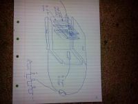
Based on another thread and water has a high constant of about 80 was thing something like below.
Think that magnetic feilds are one million times stronger than electric, that I could use the electric feild produce more power with water coils.
Edit thanks about the reverse voltage of mosfets, will put a forward direction diode to limit that.
Andy, Tue Jan 27 2015, 04:11AM
The r3&7 was just to limit the current to 25&50&100mA, it was 6.4kohm, but the sim needed a resistor on the primary of the circuit.
The parts current handling as being updated to high values.
Based on another thread and water has a high constant of about 80 was thing something like below.
Think that magnetic feilds are one million times stronger than electric, that I could use the electric feild produce more power with water coils.

Edit thanks about the reverse voltage of mosfets, will put a forward direction diode to limit that.
Re: Submarine engine
Silverfox, Fri Jan 30 2015, 03:58AM
Okay here is a disclaimer- I haven't studied anything on this particular subject so keep that in mind regarding this suggestion.
I do understand a little about what you are trying to do. First, you are going to incur a substantial energy loss in the conversion between linear to rotational energy. Here is a suggestion: There are several schematics floating around for an Oxy-Hydrodgen Torch, which basically breaks down water into the atomic components using microwave RF to assist in the breaking of the molecular bonds. These components are then recombined at the torch tip to create a localized high temperature combustion. Check out some of the videos.
Would it make more sense to try this concept and use the gases generated to run a turbine or could the gases be used to pressurize the water with in injector to create your mass flow? I believe this process either requires a microwave tube or an antenna that emits the microwaves responsible for decreasing the energy required to break the oxy-hydrogen molecular bond. Perhaps passing the water through two electrodes subjected to HF RF would work also.
A big question relates to the energy input equation/balance and the gas generation rate. The circuitry involved however is simple in design and the torch is seemingly economical to operate. Saltwater may also enhance or retard the process.
Fwiw,
Fusionstate.
Re: Submarine engine
Andy, Fri Jan 30 2015, 07:54PM
Hi silverfox, was thinking off a ,200mhz tranistor at 5 kv but will piss o many people with rf interference. Looked up water tourchs, but apart from the heat injected will only top 10% eff.got a circuit that should top 100khz and drop in eff after that, but will supply high voltage high current, but will be using dialectic heating type system, but not as heat
Re: Submarine engine
BigBad, Fri Jan 30 2015, 09:19PM
This is going to be very, very inefficient.
Fun though.
Turning a turbine with it should be significantly more efficient though; but still awful.
(Electric motors produce relatively little thrust for a given power, but at high enough speed that still represents high mechanical output power- that's why electric motors are nearly always run at high speed and geared down, using a turbine would effectively give you some gearing).
Print this page
