Gate waveform with bus voltage / gate drive voltage
chris_inkubate, Thu Jan 01 2015, 03:41PMHi all and happy new year,
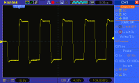
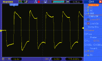
I have just been doing some work on my DRSSTC after a primary strike bypassed my strike rail and took out an IGBT. I have been scoping all my waveforms carefully and noticed something odd on my gate drive. My waveforms seem to get slopes on top when bus voltage (48V) is applied and their peak increases to 30V whilst only 24V with no bus voltage. I understand that bus voltage does affect the gate drive but didn't think in this way :
No bus voltage

48V bus voltage

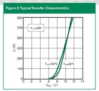
I am concerned as I don't want my gates to fail due to over voltage. I can see two options one of which is if anyone has an idea on how to fix this issue please or I can back my gate supply voltage off to 20V instead of 24V as this is on a variable regulator. Would i be correct in thinking that I can safely run my gates lower as the below graph suggests I can run up to the full rated current at around 12V minimum? This graph does however specify at a collector to emitter voltage of 20V - does anyone know what effect a higher Vce has on this graph as it isn't on the data sheet?

Many Thanks,
Chris
Re: Gate waveform with bus voltage / gate drive voltage
Antonio, Thu Jan 01 2015, 07:12PM
This appears to be effect of the primary current flowing through the ground circuit, causing some voltage drop. Look carefully at where are you connecting the oscilloscope and at how the ground circuit is wired.
Antonio, Thu Jan 01 2015, 07:12PM
This appears to be effect of the primary current flowing through the ground circuit, causing some voltage drop. Look carefully at where are you connecting the oscilloscope and at how the ground circuit is wired.
Re: Gate waveform with bus voltage / gate drive voltage
Dr. Dark Current, Thu Jan 01 2015, 09:10PM
More likely inductive coupling between the power circuit and scope probe. If you connect your probe tip to its ground while leaving the ground clip in place, you should see the falsely picked up waveform.
Dr. Dark Current, Thu Jan 01 2015, 09:10PM
More likely inductive coupling between the power circuit and scope probe. If you connect your probe tip to its ground while leaving the ground clip in place, you should see the falsely picked up waveform.
Re: Gate waveform with bus voltage / gate drive voltage
chris_inkubate, Sat Jan 03 2015, 10:52PM
Hi All,
Thanks for the feedback. I tried scoping the ground and like suggested got a noise waveform which is cause of this. Glad that my gate drive is actually OK.
chris_inkubate, Sat Jan 03 2015, 10:52PM
Hi All,
Thanks for the feedback. I tried scoping the ground and like suggested got a noise waveform which is cause of this. Glad that my gate drive is actually OK.
Re: Gate waveform with bus voltage / gate drive voltage
Goodchild, Mon Jan 05 2015, 02:29PM
Chris,
Before writing this off completely I would suggest doing a differential measurement across your gates to verify your conclusion. You can take a differential measurement simply by using both prob tips on your oscilloscope and subtracting the two channels using the math function in your oscilloscope.
If it is truly a measurement abnormality as thought, this signal should appear nominal under the differential measurement. If it's actually due to your leakage inductance in the GDT and or bus cap EST, this sloping will still be present on the gates.
Do you employ bi-directional TVS protection across your gates?
Re: Gate waveform with bus voltage / gate drive voltage
chris_inkubate, Mon Jan 05 2015, 07:21PM
Hiya,
Thanks for the additional info. I'll do a differential measurement as see what I get. I do have bidirectional TVS at 24V on each gate which is why I thought it strange. I must admit that I moved these closer to the gate connections after this as thought something may be ringing up in the cables. But now only connections inside the actual brick could have any effect with TVS being on the connections.
I certainly don't want to be loosing a brick over something solvable in the gate drive!
Many Thanks
Print this page