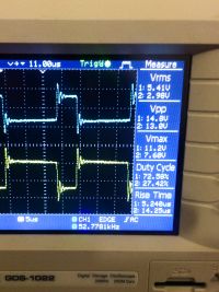
Any comments on this waveform at the gate of an unpowered IGBT before more testing?
astralhighway, Fri Nov 07 2014, 09:48AMThis is the waveform at the gate of an FGH60N60. The source signal is a square pulse through some logic, drivers and gate TX, at 50Khz.
There is an R3 resistor in series with each primary, which is virtually lead-less on the primary side. Connections are right on the body of the toroid.
The IGBTS are FGH60N60 and will be in resonant switching mode, DRSSTC, around 400KHz. Each gate has an 8R2 series resistor.
There is about 500nS per half cycle of ringing, hence 1MHz ringing. The voltage swing in the first half cycle of ringing is -5V - too much?
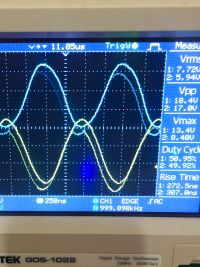
The last image is just for information. It shows a pure sine wave from the gate drive when driven at 600Khz above the design frequency, 1MHz.


Re: Any comments on this waveform at the gate of an unpowered IGBT before more testing?
Steve Conner, Fri Nov 07 2014, 10:13AM
Looks a bit ringy. Any details of your GDT construction?
Steve Conner, Fri Nov 07 2014, 10:13AM
Looks a bit ringy. Any details of your GDT construction?
Re: Any comments on this waveform at the gate of an unpowered IGBT before more testing?
astralhighway, Mon Nov 10 2014, 02:31PM
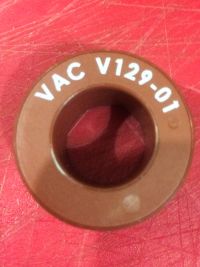
Hi Steve, It is wound on an amorphous alloy toroid, pictured, 14t hexafilar, using CatE ethernet cable.
The waveform posted was with zero length primary leads but 6 cm tail on the secondary side -- too much?
I had suspected the gate drivers needed some support so I improved the decoupling right on their pins.
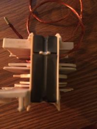
Incidentally, have you experimented using one of these cores (here from a microwave oven inverter)? Any good at 400KHz?
If not I was thinking of stripping the thinner llitz wire (not shown) to wind around the same toroid shown in the first image...
Do I need to aim for sub 2uS rise time switching at 400KHz with these IGBTs?


astralhighway, Mon Nov 10 2014, 02:31PM
Steve Conner wrote ...
Any details of your GDT construction?
Any details of your GDT construction?
Hi Steve, It is wound on an amorphous alloy toroid, pictured, 14t hexafilar, using CatE ethernet cable.
The waveform posted was with zero length primary leads but 6 cm tail on the secondary side -- too much?
I had suspected the gate drivers needed some support so I improved the decoupling right on their pins.
Incidentally, have you experimented using one of these cores (here from a microwave oven inverter)? Any good at 400KHz?
If not I was thinking of stripping the thinner llitz wire (not shown) to wind around the same toroid shown in the first image...
Do I need to aim for sub 2uS rise time switching at 400KHz with these IGBTs?


Re: Any comments on this waveform at the gate of an unpowered IGBT before more testing?
teravolt, Tue Nov 11 2014, 05:16PM
do you have a picture of your setup the whole thing? usaly a series gate resistor helps dampen persitics in the gate you may also have to much inductance in your gate drive circuit. there is a tradoff though to much resistance will slow down your mofet turn on and turn off rise and fall times. I usaly use 10 ohm for to-247 packages to 1 ohm for brick igbt's. the gate of your fet is a basialy a capacitor and how fast you can charge and discharge is one of the factors for how fast your device is. there are more detailed explinations wich some one else may have a better explination.
Print this page