Rotary spark gap old idea
dexter, Wed Aug 13 2014, 08:30PMRecently i got my hands on a working MOT and few more are incoming in the next week/s and after playing wit its resonant arcs i decided to to build that spark gap tesla coil i wanted to build many years ago: MOT - voltage doubler - homerolled caps and my 3 pole rotary spark gap.
Alot of info about DC Tesla coil i got from this

So basically in order to make a DC TC a charging circuit (resistive or inductive) has to be used for the tank capacitor which come with advantages and disadvantages...

So my idea is to use a 3 pole rotary spark gap that will dramatically reduce or even eliminate the need of a charging circuit

First electrodes 1 and 2 of the RSG come in contact connecting the HVDC to the cap charging it, moments later as the RSG advances electrode 1 is disconnected and 2 and 3 connected, connecting the charged cap to the TC primary coil which will osculate at the resonant frequency.
By using this 3 pole RSG setup the HVDC will never see a heavy load or even a short circuit as when a 2 pole SG fires (subdimensioned charging resistor or inductor) and also no HF current from the LC will go into the HVDC damaging it
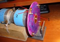
I have some pictures of my old 3 pole rotary spark gap made from glued together DVD's 1mm copper plate as 2nd electrode, 3mm bolts for 1 and 3 electrodes and a DC motor. Note that the connecting wires and central electrode on the bottom are missing

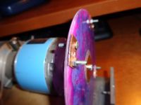
close up of the electrodes

The static electrodes were all 3 in the same plane with the motor axis and made from the same bolts. As the weal rotate the copper plate (electrode 2) and one of the bolts (electrode 1) come in contact with the static electrodes, moments later electrode 1 gets disconnected and electrode 3 get connected to its corresponding static electrode.
The coil produced horrible sparks but it was poorly designed, for the HVDC i used a PC monitor flyback so low current high voltage and the distance between all the electrodes was small that i was getting arcs between 1 and 3.bypassing the cap - basically little thinking involved
I want to start over this time sizing everything accordingly...
So what do you people tink about this 3 pole rotary spark gap?
Re: Rotary spark gap old idea
Steve Conner, Wed Aug 13 2014, 09:53PM
You always have to charge the tank capacitor through an inductor. Any other arrangement wastes 50% of the power as heat.
In a conventional AC powered coil, the ballast inductance or leakage reactance of the transformer does the job.
Steve Conner, Wed Aug 13 2014, 09:53PM
You always have to charge the tank capacitor through an inductor. Any other arrangement wastes 50% of the power as heat.
In a conventional AC powered coil, the ballast inductance or leakage reactance of the transformer does the job.
Re: Rotary spark gap old idea
loneoceans, Thu Aug 14 2014, 12:57AM
For the spark gap material, I would really recommend using a better rotor material for your safety. Not only is it not strong enough to support the forces the electrodes will put on the rotor, it also softens at a very low temperature (around 150C or less) and you are at significant risk of your disk shattering! I would recommend something like fiberglass which has an order of magnitude greater tensile strength and is much more heat resistant. In addition, I would think that a better material such as brass bolts would be an easy replacement and fair much better than steel. In your current setup, your dwell time when the circuit is in 'charge mode' is very small, and you'll need a huge surge of charge current at the time you're 'charging'. Regardless, you will still need a charging circuit as Steve said, otherwise half of the energy will be lost as heat.
Re: Rotary spark gap old idea
dexter, Thu Aug 14 2014, 05:57AM
like i said that design was long time ago when i didn't knew much about....
I know this RSG is dangerous but i posted those pictures anyway for a better understanding of my idea.
What i'm trying to find here is if this 3 pole spark gap can work better than a regular 2 pole one and if the charging circuit can be reduced since it is only used for charging the cap and not for blocking the HF current from the L-C
dexter, Thu Aug 14 2014, 05:57AM
loneoceans wrote ...
For the spark gap material, I would really recommend using a better rotor material for your safety. Not only is it not strong enough to support the forces the electrodes will put on the rotor, it also softens at a very low temperature (around 150C or less) and you are at significant risk of your disk shattering! I would recommend something like fiberglass which has an order of magnitude greater tensile strength and is much more heat resistant. In addition, I would think that a better material such as brass bolts would be an easy replacement and fair much better than steel. In your current setup, your dwell time when the circuit is in 'charge mode' is very small, and you'll need a huge surge of charge current at the time you're 'charging'. Regardless, you will still need a charging circuit as Steve said, otherwise half of the energy will be lost as heat.
For the spark gap material, I would really recommend using a better rotor material for your safety. Not only is it not strong enough to support the forces the electrodes will put on the rotor, it also softens at a very low temperature (around 150C or less) and you are at significant risk of your disk shattering! I would recommend something like fiberglass which has an order of magnitude greater tensile strength and is much more heat resistant. In addition, I would think that a better material such as brass bolts would be an easy replacement and fair much better than steel. In your current setup, your dwell time when the circuit is in 'charge mode' is very small, and you'll need a huge surge of charge current at the time you're 'charging'. Regardless, you will still need a charging circuit as Steve said, otherwise half of the energy will be lost as heat.
like i said that design was long time ago when i didn't knew much about....
I know this RSG is dangerous but i posted those pictures anyway for a better understanding of my idea.
What i'm trying to find here is if this 3 pole spark gap can work better than a regular 2 pole one and if the charging circuit can be reduced since it is only used for charging the cap and not for blocking the HF current from the L-C
Re: Rotary spark gap old idea
Hydron, Thu Aug 14 2014, 12:19PM
Unfortunately this idea isn't really feasible. You'd be trying to do two different things with one gap: charge the cap up relatively slowly (slow quench), and discharge it very quickly (fast quench). It would be difficult to accommodate both with one gap, and it is pointless anyway, as you need a ballast to control the charging and stop the gap power-arcing regardless, removing the requirement for breaking the connection to the transformer. MOTs are rugged enough to handle being connected across the gap (via a ballast choke).
Secondly, as previously mentioned, your gap is extremely dangerous! The geek group burnt down their lab with a much better constructed gap than what you've built, so don't even think of trying it for anything stronger than a flyback!
Print this page