
[moved] ZVS Induction Heater
The Lightning Stalker, Sun Jun 02 2013, 08:08AMHello everyone. I'm currently struggling with a small induction heater of the Marko variety. I'm getting some funky waveforms and am beginning to suspect the diodes. They are some FF1001 I had lying in my junj box. The MOSFETs get hot fast due to the crummy gate drive and the work does not even get warm. The choke cores are from main filter chokes salvaged from 2 identical dead BesTec power supplies and rewound with copper manget wire of long forgotten origin (probably another PSU choke). They tested around 208-220uH. They are yellow/blue cores which for someone that knows may indicate the material. There may be some imbalance here since I got way better at the winding on the second one. The calculated frequency is around 97kHz, but strangely it is oscillating at over 3MHz. I wrote up a quick little tank frequency calculator for those of us who compute with penguins.
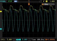
Yellow == gate, blue == drain.
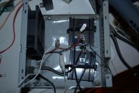
MOSFETs are IRFZ44. If you can't tell from the picture, there is LDPE sheet under the heatsinks to insulate them.
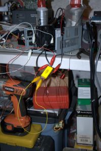
You can see the power supply I'm using to power it in the background. (12V, 10A)
Update 6/4/2013:
Success! The faulty diodes were replaced with 40V 3A Schottky type SB340. They can handle a peak current of 80A according to the datasheet. I also added a 7812 regulator on the gate charge resistors. This was a recommendation of the RMCybernetics site. It seems rather unnecessary though as the voltage is sagging down to 10V because of all the current on the alligator clips. They are doing their job though preventing things from blowing up. The work gets very hot very fast like it is supposed to.
The only potential problem I see is that the work coil gets very hot, especially when there is no work inside. The capacitor is probably heating as well, but I didn't want to have it on long enough to really observe that. It looks like I'll either need to figure out some sort of current limiting arrangement or else go for water cooling. It really is producing too much heat for the soldering I was going to do. My only other concern is the slow rise of the gate waveform and turn-off parasitics. Others I have seen do not exhibit this at all, though they were running with more voltage. Should I use lower gate charge resistance?
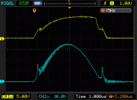
Once again, the gate is yellow and the drain is the blue. You can really see where the transistor turns on at about 5V on the gate. Lots of nice ringing going on.
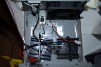
Here you can see where I have added the 7812. The heat sink is probably unnecessary, as it's not even drawing 100mA. I didn't even bother greasing it.
It's hard to see, but I soldered 2 1206 ceramic capacitors right onto the leads of the regulator. They tested at just over 80nF, so I used two just to be sure it got over the specified 100nF. They're right on top of one another.
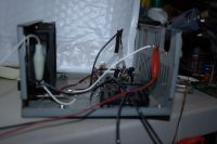
Another view in which you can see how the gate charge resistors come up out of the mess. One of the "new" Schottkies is visible. All component leads were "hooked" around one another to make soldering easier.
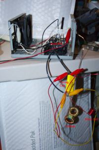
Tuning Cap = Tank Cap. Sorry, it's late and I'm dead tired.
The alligator clips aren't actually carrying any current. They are just there to hold everything in place for testing purposes. This way I can swap out components easily. Yeah, it works fine like this believe it or not. I didn't even have to shorten up the long leads on the chokes. I will definitely do this eventually though. When completed, it will all fit inside the ATX PSU case. They make great project boxes.
I plan on eventually posting a video. This isn't really a priority though. There are plenty of ZVS induction heater videos out there. I'm not that special.
Thank you all again for this wonderful forum. If it wasn't for this, I would have given up.
Re: [moved] ZVS Induction Heater
ZakWolf, Sun Jun 02 2013, 10:31PM
I think that overly long connections are bad, especially for the ZVS driver, it causes stray inductance ( im probably wrong) try shortening up the inductor and the res. cap. wires.
ZakWolf, Sun Jun 02 2013, 10:31PM
I think that overly long connections are bad, especially for the ZVS driver, it causes stray inductance ( im probably wrong) try shortening up the inductor and the res. cap. wires.
Re: [moved] ZVS Induction Heater
The Lightning Stalker, Mon Jun 03 2013, 01:34AM
Thank you for the help. I thought no one was going to respond. It does look like the inductor and cap are connected with alligator clips, but the clips are actually just holding them in place. I will however try it with everything soldered directly on and shorten up the leads on the filter chokes. Right now I'm in the process of hunting down some suitable schottky diodes. I'm also going to attach a 7812 voltage regulator to the 330 ohm gate charging resistors. I may eventually have to substitute them with a lower value, but I'll let you know how it goes.
Re: [moved] ZVS Induction Heater
Thomas W, Mon Jun 03 2013, 05:23AM
Among other things, ive been getting together the stuff to make one of these, i think you should try getting a litteral breadboard and putting some nails in it, then wind your components around the nails and hook it up like that!
Also, shouldnt this be in general electronics instead of HV as its an induction heater and not a HV ZVS?
Re: [moved] ZVS Induction Heater
The Lightning Stalker, Tue Jun 04 2013, 08:50PM
Update: I got it working. See original post.
How do you attach images when editing a post?
Never mind. I figured it out.
ATTN: Moderator: Can this be moved back to the projects section since it's working?
The Lightning Stalker, Tue Jun 04 2013, 08:50PM
Update: I got it working. See original post.
How do you attach images when editing a post?
Never mind. I figured it out.
ATTN: Moderator: Can this be moved back to the projects section since it's working?
Print this page