smaller coils (and a 12MHz target)
ragnar, Tue Aug 08 2006, 03:05AMhi all,
just wanted to post a couple of pics of what I've been working on lately:
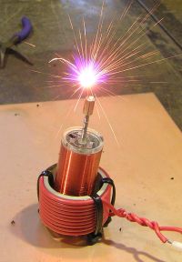
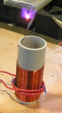
The "smaller" coil (with the neat primary) runs at ~3MHz and would have been drawing ~150W in this photo.
The "larger" coil (with the thicker wire) runs at ~6.5MHz and was drawing the same power.
Each of these is a stepping stone to a high power 12MHz coil. The former will be thick-walled Teflon tube, because Acrylic and PVC suck.
Both use a single IRFP450 running in class-E configuration with resonant-circuit gatedrive.
Re: smaller coils (and a 12MHz target)
..., Tue Aug 08 2006, 03:40AM
Looks good BP
Will you be the first one to beat EVR's 10.1MHz sstc?
A tip for those primaries... As you are winding put a small amount of superglue (CA glue) on the coilform then wind the wire. Then you don't need those wireties You can also wrap the form in waxed paper and use more glue (it works a lot better if you have several layers that you can glue to eachother) and you can have a formerless coil too.
Keep it up!
BTW, did you ever get audiomodulation going on the OMFGSTFUHFSSTC?
..., Tue Aug 08 2006, 03:40AM
Looks good BP

Will you be the first one to beat EVR's 10.1MHz sstc?
A tip for those primaries... As you are winding put a small amount of superglue (CA glue) on the coilform then wind the wire. Then you don't need those wireties
 You can also wrap the form in waxed paper and use more glue (it works a lot better if you have several layers that you can glue to eachother) and you can have a formerless coil too.
Keep it up!
BTW, did you ever get audiomodulation going on the OMFGSTFUHFSSTC?
Re: smaller coils (and a 12MHz target)
ragnar, Tue Aug 08 2006, 08:56PM
Ya, I didn't have any cyanoacrylate at school, I usually superglue my primaries and remove the former =P
This also wouldn't have happened if I hadn't dug through my stash of "dead" MOSFETs and found one that did indeed work. I'm almost completely out ^^
My gatedrivers get warm, but the heatsink on the IRFP450 stays cold.
Just yesterday I found some heatsinks big enough to allow me to try audio by amplitude modulation. There goes my efficiency

Re: smaller coils (and a 12MHz target)
Marko, Tue Aug 08 2006, 09:35PM
Bother. I didn't do much of work on my Class E coil lately.
(Rather having some 'fun' with holidays. :p )
How many mosfet's have you fried yet bp?
I think the 'Anticoil' is only thing that can have reasonable Q at that high frequencies, and also cooling is much better.
I use to fill a PVC ube with poliester resin to prevent it from falling apart once it gets stinking hot, but then connection under poliester usually goes open

Re: smaller coils (and a 12MHz target)
Part Scavenger, Thu Aug 10 2006, 12:23AM
Sweet BP! That thing looks great!
Part Scavenger, Thu Aug 10 2006, 12:23AM
Sweet BP! That thing looks great!
Re: smaller coils (and a 12MHz target)
ragnar, Thu Aug 10 2006, 11:15AM
Thanks :)
I'm not sure which impacted more, dielectric heating of the PVC former or I^2.R losses on the skimpy 0.15mm copper wire.
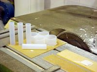
Either way, I now have thick-walled teflon PFA primary and secondary formers. It has a nice low loss tangent, and I'm winding the bugger with 0.5mm NOT-solder-through enamelled copper wire.
The best I can do for the primary is 1mm thick solid copper with 1mm-thick (radius) PVC insulation.
Can't wait to wind, terminate, and fire 'em up.


Re: smaller coils (and a 12MHz target)
ragnar, Thu Aug 10 2006, 01:54PM
LOL, trying to drop a hint at me? =P
If you really want, I'll send you my artwork for the antiformer. I went to meticulous detail to ensure that each slot was raised 1/8th of the turnpitch, and that kind of thing. It was quite elegant, if it wasn't so vain. ^^
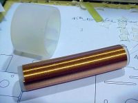
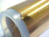
On more practical matters, I've wound the first teflon former with ~220 turns of the 0.5mm copper. Pretty. =)


Re: smaller coils (and a 12MHz target)
Marko, Thu Aug 10 2006, 02:16PM
Hm, now you stole my idea about winding HF coils on round formers.. partly at least =)
Longer ago I tought about using a big multifilar braid of wires wound around a pvc tube, but that would require large number of separate wire sources, and twisting few tens of them together in wanted length would also be a pain.
Winding it the way you did on last pic is easier but I doubt you'l get a big Q increase with low number of very thick wires (you can always try it).
I want some really low impedance here, maybe even a possibility to drive e resoantor directly without a primary on reasonable voltages.
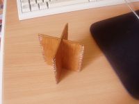
The funny wooden thing I had here is dipped in poliester for fixing, but plywood is ofcourse too chippy to make fine edge carvings. I didn't really care how is it going to look afterall (since I had no chance to make something similar out of acrylic like your form).
It was raather aresult of boredom (poliprojectitis) than some very practical use.
More serious thing I can try would be using some kind of mould and fiberglassing it, but that was too much work :p
Re: smaller coils (and a 12MHz target)
ragnar, Thu Aug 10 2006, 02:32PM

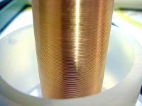
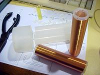
Done number two... the great thing about my coils is they take so little time to wind =-D
I've got no idea what frequency these'll resonate at. I just hope it's less than 6.5, because that was a little tricky, and tweaking four of them at once won't be fun. =P
ragnar, Thu Aug 10 2006, 02:32PM
wrote ...
Hm, now you stole my idea about winding HF coils on round formers.. partly at least
Hm, now you stole my idea about winding HF coils on round formers.. partly at least

Done number two... the great thing about my coils is they take so little time to wind =-D
I've got no idea what frequency these'll resonate at. I just hope it's less than 6.5, because that was a little tricky, and tweaking four of them at once won't be fun. =P


Re: smaller coils (and a 12MHz target)
ragnar, Thu Aug 10 2006, 03:28PM
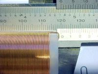
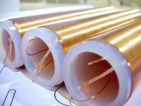
Hooray, finished #3 of four.
And now I'm out of wire. Shit.
Goodnight. ^^
ragnar, Thu Aug 10 2006, 03:28PM
Hooray, finished #3 of four.
And now I'm out of wire. Shit.

Goodnight. ^^


Re: smaller coils (and a 12MHz target)
Marko, Thu Aug 10 2006, 03:59PM
And I just wanted to say that golden wire looks very cool =)
I guess you are trying to make a 4-channel audio system..?
Nice BP...
Marko, Thu Aug 10 2006, 03:59PM
And I just wanted to say that golden wire looks very cool =)
I guess you are trying to make a 4-channel audio system..?
Nice BP...
Re: smaller coils (and a 12MHz target)
ragnar, Thu Aug 10 2006, 05:22PM
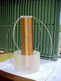
All hail the anticoil... working on speedstripes and fins now =P
ragnar, Thu Aug 10 2006, 05:22PM
All hail the anticoil... working on speedstripes and fins now =P

Re: smaller coils (and a 12MHz target)
Steve Ward, Thu Aug 10 2006, 05:49PM
Well congrats...
Maybe you can find some litz wire on ebay if your trifilar winding still overheats? It would give much more surface area compared to just 3 conductors. Though, what you have there looks like it should get you good results.
Can you try to use a breakout point that doesnt explode into a shower of sparks? It would be nice to see the actual discharge, to note any differenced compared to a "low" frequency SSTC.
Steve Ward, Thu Aug 10 2006, 05:49PM
Done number two...
Well congrats...

Maybe you can find some litz wire on ebay if your trifilar winding still overheats? It would give much more surface area compared to just 3 conductors. Though, what you have there looks like it should get you good results.
Can you try to use a breakout point that doesnt explode into a shower of sparks? It would be nice to see the actual discharge, to note any differenced compared to a "low" frequency SSTC.
Re: smaller coils (and a 12MHz target)
Steve Conner, Fri Aug 11 2006, 11:09AM
Fins? WTF, it's a Tesla coil, not a light sabre.
Firkragg: Winding a high frequency coil on a tubular former made of low-loss material is hardly a new idea I've even seen things like BP's skeleton coil former inside radio transmitters, but made of ceramic.
I don't think the winding is trifilar.
Steve Conner, Fri Aug 11 2006, 11:09AM
Fins? WTF, it's a Tesla coil, not a light sabre.

Firkragg: Winding a high frequency coil on a tubular former made of low-loss material is hardly a new idea
 I've even seen things like BP's skeleton coil former inside radio transmitters, but made of ceramic.
I don't think the winding is trifilar.
Re: smaller coils (and a 12MHz target)
Electroholic, Fri Aug 11 2006, 11:16AM
looks like bp ends his coils with 3 half-turns thru the former.
Electroholic, Fri Aug 11 2006, 11:16AM
looks like bp ends his coils with 3 half-turns thru the former.
Re: smaller coils (and a 12MHz target)
Marko, Fri Aug 11 2006, 12:33PM
I was talking about bp'S 'golden' coils; they are wound using 3 wires together, but all lined up on same form.
It looks very nicce but I still think 'skeleton' coils with large amounts of thinner wires beat it on some level..
Marko, Fri Aug 11 2006, 12:33PM
I don't think the winding is trifilar.
I was talking about bp'S 'golden' coils; they are wound using 3 wires together, but all lined up on same form.
It looks very nicce but I still think 'skeleton' coils with large amounts of thinner wires beat it on some level..
Re: smaller coils (and a 12MHz target)
ragnar, Fri Aug 11 2006, 12:56PM
The golden coils are single-filar, terminated both ends with half-turns through the former as Electroholic observed.
ragnar, Fri Aug 11 2006, 12:56PM
The golden coils are single-filar, terminated both ends with half-turns through the former as Electroholic observed.
Re: smaller coils (and a 12MHz target)
Steve Ward, Fri Aug 11 2006, 06:58PM
You are the master of confusion BP .
.
Steve Ward, Fri Aug 11 2006, 06:58PM
You are the master of confusion BP
 .
.Re: smaller coils (and a 12MHz target)
ragnar, Sat Aug 12 2006, 06:56AM
Why thankyou. Not my intention, but I'm sure it's an admirable quality =P
Just for kicks, I'm going to wind the fourth former with 0.25mm wire to make the frequency a little more manageable and see how it performs.
ragnar, Sat Aug 12 2006, 06:56AM
Steve Ward wrote ...
You are the master of confusion BP .
.
You are the master of confusion BP
 .
.Why thankyou. Not my intention, but I'm sure it's an admirable quality =P
Just for kicks, I'm going to wind the fourth former with 0.25mm wire to make the frequency a little more manageable and see how it performs.
Re: smaller coils (and a 12MHz target)
ragnar, Wed Aug 16 2006, 07:58AM
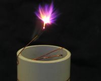
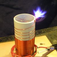
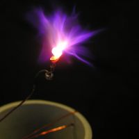
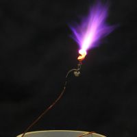
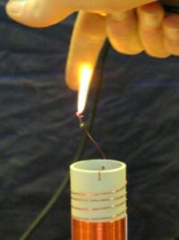
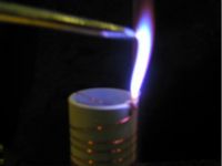
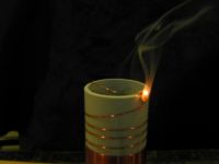
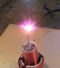
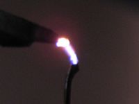
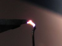
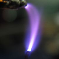
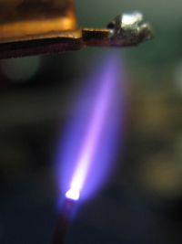
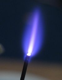
The images/colours you see here are a very good representation of what I see in real life... the 'blue plasma brush' pic has an exposure a little long... but the streamers are very full, VERY hot, very silent..
The colour changes, too: Initially they're your typical corona purple colour. As the copper wire heats up and starts to ball, they go light and lilacey... and as the PVC starts to smoke, they take on a blue and red tinge depending on the proximity to the fumes. The presence of burning-flesh-fumes makes the arc go yellow. ^^
6.5MHz is pretty?


Re: smaller coils (and a 12MHz target)
HV Enthusiast, Wed Aug 16 2006, 11:13AM
Cool. Looks sweet!
HV Enthusiast, Wed Aug 16 2006, 11:13AM
Cool. Looks sweet!
Re: smaller coils (and a 12MHz target)
Part Scavenger, Wed Aug 16 2006, 11:29AM
Cool.
Part Scavenger, Wed Aug 16 2006, 11:29AM
Cool.
Re: smaller coils (and a 12MHz target)
Marko, Wed Aug 16 2006, 11:44AM
m, omg, can you post a pic of your finger from 5.th pic

(ps. don't say it was birthday attraction for girls or something )
)
Anyway nice pics, what arc length do you get..?
One thing I wonderedis, is resonant gate drive actually more efficient than 'normal' (not counting that it is way easier to drive)
I'm using common resistive drive and putting stress to UCC, while it may not be important at all..?
Problem on a fixed board would be if I replace mosfet's I would need to retune the choke somehow too..
Marko, Wed Aug 16 2006, 11:44AM
m, omg, can you post a pic of your finger from 5.th pic


(ps. don't say it was birthday attraction for girls or something
 )
)Anyway nice pics, what arc length do you get..?
Both use a single IRFP450 running in class-E configuration with resonant-circuit gatedrive.
One thing I wonderedis, is resonant gate drive actually more efficient than 'normal' (not counting that it is way easier to drive)
I'm using common resistive drive and putting stress to UCC, while it may not be important at all..?
Problem on a fixed board would be if I replace mosfet's I would need to retune the choke somehow too..
Re: smaller coils (and a 12MHz target)
ragnar, Wed Aug 16 2006, 11:54AM
It's quite fiddly to tune though, especially at 6.5MHz.
I'll be using IRF510s in the final gatedriver stage on the 12MHz model.
ragnar, Wed Aug 16 2006, 11:54AM
wrote ...
m, omg, can you post a pic of your finger from 5.th pic

'fraid there was no marring of my finger -- I flicked the discharge really only long enough for the camera.m, omg, can you post a pic of your finger from 5.th pic


wrote ...
Anyway nice pics, what arc length do you get..?
The blue arc drawn to a screwdriver (in the images above) was probably just under two inches in length.Anyway nice pics, what arc length do you get..?
wrote ...
One thing I wonderedis, is resonant gate drive actually more efficient than 'normal' (not counting that it is way easier to drive)
Depends what the amplitude of the sinewave is, whether or not you have a DC bias applied to the gate, the Q of the circuit, etc. I can keep my UCCs a lot cooler because I'm driving a small GDT +/- 12V with a stepdown ratio of about 4:1 - so the current is stepped up four times... and the voltage resonates back up to what I was driving the primary with anyway. =-DOne thing I wonderedis, is resonant gate drive actually more efficient than 'normal' (not counting that it is way easier to drive)
It's quite fiddly to tune though, especially at 6.5MHz.
I'll be using IRF510s in the final gatedriver stage on the 12MHz model.
Re: smaller coils (and a 12MHz target)
ragnar, Sun Aug 20 2006, 03:18AM
Getting there... this'd better work. =P
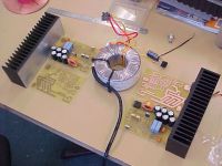

ragnar, Sun Aug 20 2006, 03:18AM
Getting there... this'd better work. =P


Re: smaller coils (and a 12MHz target)
ragnar, Sun Aug 20 2006, 01:35PM
Hmm, getting multiple coils to work simultaneously in close proximity... driving... me... crazy...
ragnar, Sun Aug 20 2006, 01:35PM
Hmm, getting multiple coils to work simultaneously in close proximity... driving... me... crazy...

Re: smaller coils (and a 12MHz target)
ragnar, Fri Aug 25 2006, 11:07AM
Hooray, first light from one... Now, shall work on two. =P
Could look better, though.
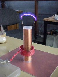
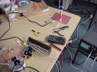
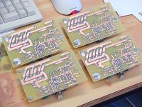
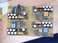
ragnar, Fri Aug 25 2006, 11:07AM
Hooray, first light from one... Now, shall work on two. =P
Could look better, though.


Re: smaller coils (and a 12MHz target)
Wilson, Fri Aug 25 2006, 11:50AM
Are you using a CD4046 chip as an oscillator Matt?
I really like the boards btw
Wilson, Fri Aug 25 2006, 11:50AM
Are you using a CD4046 chip as an oscillator Matt?
I really like the boards btw

Re: smaller coils (and a 12MHz target)
Steve Conner, Fri Aug 25 2006, 11:53AM
Wee! Looks awesome Matt! So each of those boards is a complete Class-E SSTC driver that can be FM audio modulated?
Steve Conner, Fri Aug 25 2006, 11:53AM
Wee! Looks awesome Matt!
 So each of those boards is a complete Class-E SSTC driver that can be FM audio modulated?
Re: smaller coils (and a 12MHz target)
Marko, Fri Aug 25 2006, 12:20PM
Steve why is your name flipped over?
Great work BP.. (just not to be fully offtopic)
Marko, Fri Aug 25 2006, 12:20PM
Steve why is your name flipped over?

Great work BP.. (just not to be fully offtopic)
Re: smaller coils (and a 12MHz target)
ragnar, Fri Aug 25 2006, 01:39PM
yes evetS, each board (tentatively) is a 6.5MHz class-E amp. Until I build a class-H modulator or get my funky linear modulator working, audio is by frequency modulation, which works quite acceptably if you hang around on the inductive side of the Fres (f > fres)... then again, as soon as I increase the modulation depth for greater sound output, the nonlinearity turns it all to crap. =P
The difficulty is getting them to work without interfering with each other
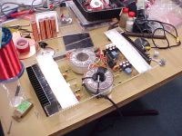
And since you guys have gone quiet, I'll tempt your feedback with more pics...
maybe I need to pull a TDU and hint that I'm not disclosing information until I get signs of interest ^^
Mmm, burning the midnight CO2 at 2:20AM
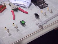
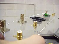
Aw, you guys are boring. Really. =P No fun whatsoever.

[Edit: Triple post, totally against the rules and stuff]
ragnar, Fri Aug 25 2006, 01:39PM
yes evetS, each board (tentatively) is a 6.5MHz class-E amp. Until I build a class-H modulator or get my funky linear modulator working, audio is by frequency modulation, which works quite acceptably if you hang around on the inductive side of the Fres (f > fres)... then again, as soon as I increase the modulation depth for greater sound output, the nonlinearity turns it all to crap. =P
The difficulty is getting them to work without interfering with each other


And since you guys have gone quiet, I'll tempt your feedback with more pics...
maybe I need to pull a TDU and hint that I'm not disclosing information until I get signs of interest ^^
Mmm, burning the midnight CO2 at 2:20AM


Aw, you guys are boring. Really. =P No fun whatsoever.


[Edit: Triple post, totally against the rules and stuff]
Re: smaller coils (and a 12MHz target)
Wilson, Sat Aug 26 2006, 01:09PM
How come your stuff always seems so elegant
My work looks like crap next to it XD
Wilson, Sat Aug 26 2006, 01:09PM
How come your stuff always seems so elegant

My work looks like crap next to it XD
Re: smaller coils (and a 12MHz target)
Avalanche, Sat Aug 26 2006, 01:37PM
Does that case all slot together then?
However it goes, that's going to be one incredible case.
Avalanche, Sat Aug 26 2006, 01:37PM
Does that case all slot together then?
However it goes, that's going to be one incredible case.

Re: smaller coils (and a 12MHz target)
..., Sat Aug 26 2006, 09:43PM
What kind of volume are you getting out of it? With all 4 going you should 'only' need like 80db out of a single coil for plenty for a decent listening volume...
That box... It is... A few more dials on the front would be nice tho
I want to see what you resonators look like to match that I still think that the THz spectrometer I am working on is better tho...
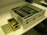
Just don't tell anyone that I gave you that pic
..., Sat Aug 26 2006, 09:43PM
What kind of volume are you getting out of it? With all 4 going you should 'only' need like 80db out of a single coil for plenty for a decent listening volume...
That box... It is...
 A few more dials on the front would be nice tho
I want to see what you resonators look like to match that
 I still think that the THz spectrometer I am working on is better tho...
Just don't tell anyone that I gave you that pic

Re: smaller coils (and a 12MHz target)
ragnar, Tue Aug 29 2006, 02:50AM
Mmm, 1200W of RF at up to 6.5MHz... the FCC is gonna lynch me.
Anybody dare to comment? ^^
Bet nobody but SteveC can guess the magical secrets behind this GDT, either...
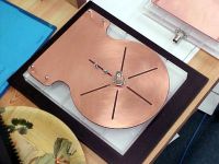
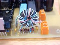
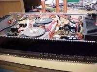
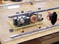
ragnar, Tue Aug 29 2006, 02:50AM
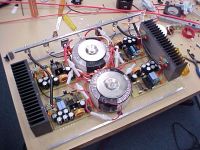
Mmm, 1200W of RF at up to 6.5MHz... the FCC is gonna lynch me.

Anybody dare to comment? ^^
Bet nobody but SteveC can guess the magical secrets behind this GDT, either...


Re: smaller coils (and a 12MHz target)
..., Tue Aug 29 2006, 04:14AM
Looks good Me wants plasma hehe
You have me stumped with that gdt; if I didn't know that you only had a single fet I would have guessed it was a 4:2:1 gdt for some pure evil purpose... The ~12 turn winding is definantly going to the ucc's (looking at the shot of the bottom of the boards) and somehow the 2 other windigs end up going into the screw terminals... The 4 diodes appear to be set up as a bridge rectifier... Ao I am going to have to guess that it is a power isolation transformer, it is fed by the ucc's and has a center tapped primary giving somewhere arround 10v out being regulated by the resistor/zener and filtered with the little cap. The asemectrical windings (ie 3 for the red and 6 for the blue) would imply that you are putting out something like +30v/-15v, but their are only 2 terminals and the output windings don't appeat grounded so I can't imagine why you would have done that
..., Tue Aug 29 2006, 04:14AM
Looks good
 Me wants plasma hehe
You have me stumped with that gdt; if I didn't know that you only had a single fet I would have guessed it was a 4:2:1 gdt for some pure evil purpose... The ~12 turn winding is definantly going to the ucc's (looking at the shot of the bottom of the boards) and somehow the 2 other windigs end up going into the screw terminals... The 4 diodes appear to be set up as a bridge rectifier... Ao I am going to have to guess that it is a power isolation transformer, it is fed by the ucc's and has a center tapped primary giving somewhere arround 10v out being regulated by the resistor/zener and filtered with the little cap. The asemectrical windings (ie 3 for the red and 6 for the blue) would imply that you are putting out something like +30v/-15v, but their are only 2 terminals and the output windings don't appeat grounded so I can't imagine why you would have done that

Re: smaller coils (and a 12MHz target)
ragnar, Tue Aug 29 2006, 05:42AM
Not a bad guess at all, Peter!
This little innovation puts a DC bias voltage on the gate so long as the gatedriver is running.
What you see there is a green 11-turn primary going to the UCCs. This cops +/-15V direct drive from the UCCs (with capacitor decoupling).
The 2-turn orange secondary therefore has +/-2.7V present on it, which you'd hardly think is enough to swing a FET, but together with a little added inductance (five turns of enamelled wire around my screwdriver, slipped off and soldered in series with the gate), the leakage inductance of the transformer resonates with the mosfet's gate capacitance, rising back up to about +/-14V. (Q is about five).
The six-turn winding in blue is fullwave rectified with a bridge of 1N4148s, giving about 8V. From the bridge, a 3K resistor limits the current, charging the little capacitor. The zener diode limits the capacitor's voltage to 6.2V.
Now the orange secondary is simply added to the blue bias circuit, resulting in a ~+20V/-8V drive on the FET. A 10K resistor is connected across the DC blocking/smoothing/bias capacitor, and it bleeds down very quickly when the gatedriver is turned off. It's almost foolproof. If the DC biasing circuit fails, the gate drops to +/-14V. The DC bias circuit is powered by the gatedriver, so you can't end up with a FET left on. Hooray!
Re: smaller coils (and a 12MHz target)
..., Tue Aug 29 2006, 02:27PM
And I though that putting a 1k resistor across the gate was genius
I like your resonant gate drive, it sounds like something I would see in a commercial piece of equipment (that I would be staring at going wtf?!? ) The joys of classe'
As to the whole problem with this thing being a 1.2kw rt transmitter... Could you put the resonators in a Faraday cage? I bet if you spent enough time on it and then gold plated it it would look as good as the rest
..., Tue Aug 29 2006, 02:27PM
And I though that putting a 1k resistor across the gate was genius

I like your resonant gate drive, it sounds like something I would see in a commercial piece of equipment (that I would be staring at going wtf?!? ) The joys of classe'
As to the whole problem with this thing being a 1.2kw rt transmitter... Could you put the resonators in a Faraday cage? I bet if you spent enough time on it and then gold plated it it would look as good as the rest

Re: smaller coils (and a 12MHz target)
Self Defenestrate, Wed Aug 30 2006, 01:23AM
I am halfway to completely lost in this thing, but wow-E thats looking sharp!
Self Defenestrate, Wed Aug 30 2006, 01:23AM
I am halfway to completely lost in this thing, but wow-E thats looking sharp!
Re: smaller coils (and a 12MHz target)
..., Wed Aug 30 2006, 03:02AM
And it wouldn't surprise me if the quality of your driver is actually BETTER than that of the $100k THz spectrometer that I was helping design (I resigned today since school starts tuesday and I still need to get my sstc and nd:yag obliterator going)...
My criteria being:
1. Ours has headers made out of 22awg wire (150 pins per unit made by yours truly)
2. Ours has bits of wirewarp wire running around through vias on the board
3. The wiring I did on ours looks ~4x as good as the rest of the wiring
4. Ours was built by a 16 year old
5. On the todo list for ours there was a note:
"get bigger fuses the 3a ones blow out "
"
On the other hand yours:
1. Has a custom designed gdt to give foolproof gate drive
2. Has a very low inductance layout
3. Uses the inductance of the wiring to its advantage
4. Was built by a 18 year old
5. Emits at a much more reasonably 6mhz as opposed to this dangerous THz stuff (well not yet at least )
)
..., Wed Aug 30 2006, 03:02AM
And it wouldn't surprise me if the quality of your driver is actually BETTER than that of the $100k THz spectrometer that I was helping design (I resigned today since school starts tuesday and I still need to get my sstc and nd:yag obliterator going)...
My criteria being:
1. Ours has headers made out of 22awg wire (150 pins per unit made by yours truly)
2. Ours has bits of wirewarp wire running around through vias on the board
3. The wiring I did on ours looks ~4x as good as the rest of the wiring
4. Ours was built by a 16 year old
5. On the todo list for ours there was a note:
"get bigger fuses the 3a ones blow out
 "
"
On the other hand yours:
1. Has a custom designed gdt to give foolproof gate drive
2. Has a very low inductance layout
3. Uses the inductance of the wiring to its advantage
4. Was built by a 18 year old
5. Emits at a much more reasonably 6mhz as opposed to this dangerous THz stuff (well not yet at least
 )
)Re: smaller coils (and a 12MHz target)
Avalanche, Wed Aug 30 2006, 10:12AM
I'd vote for this to appear on 'featured project' on the front page
When you get first light/sound/temporal disturbance that is
Avalanche, Wed Aug 30 2006, 10:12AM
I'd vote for this to appear on 'featured project' on the front page

When you get first light/sound/temporal disturbance that is

Re: smaller coils (and a 12MHz target)
ragnar, Wed Aug 30 2006, 08:43PM
I think you're giving me more credit than I deserve... =P
ragnar, Wed Aug 30 2006, 08:43PM
... wrote ...
1. Has a custom designed gdt to give foolproof gate drive
2. Has a very low inductance layout
3. Uses the inductance of the wiring to its advantage
4. Was built by a 18 year old
5. Emits at a much more reasonably 6mhz as opposed to this dangerous THz stuff (well not yet at least )
)
1. Has a custom designed gdt to give foolproof gate drive
2. Has a very low inductance layout
3. Uses the inductance of the wiring to its advantage
4. Was built by a 18 year old
5. Emits at a much more reasonably 6mhz as opposed to this dangerous THz stuff (well not yet at least
 )
)I think you're giving me more credit than I deserve... =P
Re: smaller coils (and a 12MHz target)
..., Wed Aug 30 2006, 09:35PM
I need to coax some spark pix, some artwork, and some boards out of you
..., Wed Aug 30 2006, 09:35PM
I need to coax some spark pix, some artwork, and some boards out of you

Re: smaller coils (and a 12MHz target)
Steve Conner, Wed Aug 30 2006, 10:43PM
... I work for a company that makes laser and optical gear. I showed my boss your post and he says he'll never buy an Emcore THz spectrometer now, and tell all his friends not to buy one either Seriously, I guess it's a prototype, and prototypes always look a bit scary. Our prototype laser drivers are a mass of breadboard, superglue and wire-wrap wires (that always fall off at random without anyone noticing and cause huge grief) but by the time they make it to production they are nice and neat.
Blackplasma let's see that thing going! Or catching fire or whatever. To stop the FCC (or whatever the equivalent is in aus) kicking your butt it's usual to use 13.56 or 27.12MHz, these are the "ISM bands" designated for industrial RF heating gear and such like.
I'd also vote for featured project.
Steve Conner, Wed Aug 30 2006, 10:43PM
... I work for a company that makes laser and optical gear. I showed my boss your post and he says he'll never buy an Emcore THz spectrometer now, and tell all his friends not to buy one either
 Seriously, I guess it's a prototype, and prototypes always look a bit scary. Our prototype laser drivers are a mass of breadboard, superglue and wire-wrap wires (that always fall off at random without anyone noticing and cause huge grief) but by the time they make it to production they are nice and neat.
Blackplasma let's see that thing going! Or catching fire or whatever. To stop the FCC (or whatever the equivalent is in aus) kicking your butt it's usual to use 13.56 or 27.12MHz, these are the "ISM bands" designated for industrial RF heating gear and such like.
I'd also vote for featured project.
Re: smaller coils (and a 12MHz target)
..., Wed Aug 30 2006, 11:24PM
They already sold these 5 They should neaten up the wiring a little and they ordered the correct headers for the rest of the units but...
I should poin out the only time I heard the circuit guy laugh during the 2 months I was working there was when I noted that "this is how I do things at home when he told me to build him some 72pin headers out of 22awg wire and to sand down the sockets becuase the plastic was too thick on the ends for them to stack end to end. hehe, for $100k you would THINK you would get something better...
BP definantly deservs front page status; just as soon as I see 4 resonators playing ac/dc
I also want to ask you that to try using graphite as a breakout point; I want to see how it holds up at 6mhz
..., Wed Aug 30 2006, 11:24PM
They already sold these 5
 They should neaten up the wiring a little and they ordered the correct headers for the rest of the units but...
I should poin out the only time I heard the circuit guy laugh during the 2 months I was working there was when I noted that "this is how I do things at home
 when he told me to build him some 72pin headers out of 22awg wire and to sand down the sockets becuase the plastic was too thick on the ends for them to stack end to end. hehe, for $100k you would THINK you would get something better...
BP definantly deservs front page status; just as soon as I see 4 resonators playing ac/dc

I also want to ask you that to try using graphite as a breakout point; I want to see how it holds up at 6mhz
Re: smaller coils (and a 12MHz target)
ragnar, Sun Sept 10 2006, 06:07AM
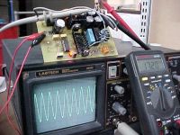
Testing the limits of UCCs here... with no load, their outputs start to die to nothing at ~18MHz.
Here they are driving two IRF510s (resonant circuit through GDT) at 17.2MHz. The IRF510s will form a halfbridge, for driving the gate of an IRFP450 or similar, through another ferrite transformer.

Re: smaller coils (and a 12MHz target)
Marko, Sun Sept 10 2006, 01:17PM
I see you are soon going to set a resonance with subspace fabric
With a resonant drive practically only limt are delay times of UCC chip.
As school started again I'l also be back soon to my class E stuff..
Marko, Sun Sept 10 2006, 01:17PM
I see you are soon going to set a resonance with subspace fabric

With a resonant drive practically only limt are delay times of UCC chip.
As school started again I'l also be back soon to my class E stuff..
Re: smaller coils (and a 12MHz target)
ragnar, Sun Sept 10 2006, 01:31PM
Actually, I point out that the frequency limitation (even with zero load) of the UCC chip is 18MHz.
Also worth noting that the UCC37322 and UCC37321 chips give different waveforms... presumably because the buffer/inverter stage incorporate different delay times... so the output waveforms are asymmetrical and there is probably cross-conduction. I'll see if this is worth solving with a 74HC inverter or something... or not =-P
Practically speaking, you wouldn't want to be driving a load much bigger than maybe ~500pF total at 17MHz.. the UCCs just can't handle it, they latch up.
To make the gate capacitance a little more predictable, I partly swamp it with a 100pF ceramic capacitor on each IRF510, bringing the total apparent gate capacitance to 235pF each. I'm using an 11:2 ferrite to couple the UCCs to the IRF510, and even then it's a struggle, so I have put little heatsinks on the plastic packages... they seem to keep them just cool enough to stop the latching. =-P
Re: smaller coils (and a 12MHz target)
Marko, Sun Sept 10 2006, 02:01PM
Maybe you could just put away the UCC's and use simple totem pole driving small class E preamplifier ala richie burnett.
Or maybe dual DEIC420driver for squarewave at 20 Mhz :) Since you are rich it won't be a big problem for you..
Much bigger problem I see is that IRFP450 won't be capable of moving his ass at 18Mhz respectably.
Maybe you could try paralelling smaller mosfets to gain some speed...
Re: smaller coils (and a 12MHz target)
ragnar, Sun Sept 10 2006, 02:06PM
ragnar, Sun Sept 10 2006, 02:06PM
Firkragg wrote ...
Maybe you could just put away the UCCs
No.Maybe you could just put away the UCCs
wrote ...
Or maybe dual DEIC420driver for squarewave at 20 Mhz
No. I challenge you to find them.Or maybe dual DEIC420driver for squarewave at 20 Mhz
wrote ...
Since you are rich it won't be a big problem for you..
No. Wrong.Since you are rich it won't be a big problem for you..
wrote ...
Much bigger problem I see is that IRFP450 won't be capable of moving his ass at 18Mhz respectably.
[edit] [edit] Wrong again.Much bigger problem I see is that IRFP450 won't be capable of moving his ass at 18Mhz respectably.
Re: smaller coils (and a 12MHz target)
Marko, Sun Sept 10 2006, 02:18PM
Ok, that about DEIC420's was just my fantasy..
Class E gatedriver can obivously beat UCC's at some level (especially if you want to go for 20Mhz +).
Your current quadro-plasma audio system is cool enough already and UCC's seem to work very fine there.
Regarding IRFP450; he has 170nS total delay times and at 18Mhz one wave lasts 55ns
That's why I'm not sure if he can stand that ^^
Anyway, have good luck as experimental evidence is most prized thing.. :)
Marko, Sun Sept 10 2006, 02:18PM
Ok, that about DEIC420's was just my fantasy..
Class E gatedriver can obivously beat UCC's at some level (especially if you want to go for 20Mhz +).
Your current quadro-plasma audio system is cool enough already
 and UCC's seem to work very fine there.
Regarding IRFP450; he has 170nS total delay times and at 18Mhz one wave lasts 55ns

That's why I'm not sure if he can stand that ^^
Anyway, have good luck as experimental evidence is most prized thing.. :)
Re: smaller coils (and a 12MHz target)
Steve Conner, Sun Sept 10 2006, 11:44PM
28MHz with IRF540s seems to be the record to beat.


Steve Conner, Sun Sept 10 2006, 11:44PM
28MHz with IRF540s seems to be the record to beat.


Re: smaller coils (and a 12MHz target)
Avalanche, Mon Sept 11 2006, 12:35AM
Woh, how are you driving the UCCs at 18Mhz, I mean do you need some kind of resonant UCC drive at that frequency, or are they just connected to some TTL logic generating the 18Mhz?
I can understand that kind of frequency at class-E, but is UCC input capacitance an issue at 18Mhz?
class-E is looking good. I never would have guessed UCCs could do that, I thought they were old slow drivers. I think I'm going to have to get into the class-E thing, starting tomorrow...

Re: smaller coils (and a 12MHz target)
Marko, Mon Sept 11 2006, 10:48AM
Wow, that is_nice, considering 540 isn't that much faster than 450 at all!
I didn't know that class-e dedicated forum before, it is about transmitters but frequencies and etc. are closely related to TC range!
Should look around this troughly!
Marko, Mon Sept 11 2006, 10:48AM
Wow, that is_nice, considering 540 isn't that much faster than 450 at all!
I didn't know that class-e dedicated forum before, it is about transmitters but frequencies and etc. are closely related to TC range!
Should look around this troughly!
Re: smaller coils (and a 12MHz target)
Marcus Wagner, Tue Sept 12 2006, 08:49PM
@Blackplasma
You work is awesome! I tried several times at class-E but ever failed.... (I tried the circuits from Richie and Steve)
What exact circuit do you use for this impressive work? I mean is there a circuit diagram/schematic available? I would appreciate it much....
Greets,
Marcus
Re: smaller coils (and a 12MHz target)
ragnar, Mon Oct 02 2006, 06:40AM
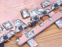
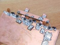
And now, ladies and gentlemen... for my next trick:
ragnar, Mon Oct 02 2006, 06:40AM
And now, ladies and gentlemen... for my next trick:


Re: smaller coils (and a 12MHz target)
Steve Conner, Mon Oct 02 2006, 10:12AM
I don't know what to say except O___O
Steve Conner, Mon Oct 02 2006, 10:12AM
I don't know what to say except O___O
Re: smaller coils (and a 12MHz target)
ragnar, Mon Oct 02 2006, 10:15AM
Steve, you spoke too soon
These have the inputs and outputs bussed properly in the hope of getting better synchronisation... they're incredibly picky at 17MHz
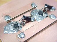
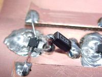
ragnar, Mon Oct 02 2006, 10:15AM
Steve, you spoke too soon

These have the inputs and outputs bussed properly in the hope of getting better synchronisation... they're incredibly picky at 17MHz


Re: smaller coils (and a 12MHz target)
Marko, Mon Oct 02 2006, 10:56AM
OMG pwnzd...
Marko, Mon Oct 02 2006, 10:56AM
OMG pwnzd...
Re: smaller coils (and a 12MHz target)
Avalanche, Mon Oct 02 2006, 12:50PM
I've never seen surface mount components mounted on the edge of the board
Avalanche, Mon Oct 02 2006, 12:50PM
I've never seen surface mount components mounted on the edge of the board

Re: smaller coils (and a 12MHz target)
Wilson, Mon Oct 02 2006, 02:25PM
I guess functionality comes before aesthetics
Wilson, Mon Oct 02 2006, 02:25PM
I guess functionality comes before aesthetics

Re: smaller coils (and a 12MHz target)
teravolt, Mon Oct 02 2006, 07:40PM
does it work
teravolt, Mon Oct 02 2006, 07:40PM
does it work
Re: smaller coils (and a 12MHz target)
Marko, Mon Oct 02 2006, 08:25PM
I guess it does but not as well as it could if he etched some board and placed those UCC's closer and nicer..
The second one looks somewhat better though..
Marko, Mon Oct 02 2006, 08:25PM
teravolt wrote ...
does it work
does it work
I guess it does but not as well as it could if he etched some board and placed those UCC's closer and nicer..
The second one looks somewhat better though..
Re: smaller coils (and a 12MHz target)
..., Mon Oct 02 2006, 10:51PM
hehe, good to see my 3oz copper pcb getting some use, since it is too thick to be chemically etched worth a crap
And since the ucc's seem to be able to drive the fet at 17mhz, you should have no problems getting the 12mhz coils of yours working?
Do you think it might help a little to put some small smd ceramics right across the power pins to ground?
..., Mon Oct 02 2006, 10:51PM
hehe, good to see my 3oz copper pcb getting some use, since it is too thick to be chemically etched worth a crap

And since the ucc's seem to be able to drive the fet at 17mhz, you should have no problems getting the 12mhz coils of yours working?
Do you think it might help a little to put some small smd ceramics right across the power pins to ground?
Re: smaller coils (and a 12MHz target)
ragnar, Sun Oct 08 2006, 09:35AM
Those were SMD tantalums across the rails... the underside of the second style of board is the +ve plane. After drilling and countersinking the top/gnd side, I made feedthroughs, which you see connecting to pin1 and pin8 on the chip (and also the tantalums)
17MHz?
Well, that's the thing... the UCCs do "work" at 17MHz... but I discovered (it was no surprise) that they're not nearly reliable enough to be usable. Note that even with no load, after several minutes they get stinking hot, until they latch or go into runaway. Add a load, and it's hopeless after about a minute. The bipolars in the output stage just aren't fast enough.
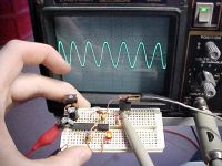
Lower that to 13.56MHz, and the output waveforms are very shakey... I note specifically that only the UCCX7322 (non-inverting) is useful at this frequency. The output inverting UCCX7321 doesn't quite get to the supply voltage, and the output pulse is too slopey, and only occupies ~25-30% of the cycle!
After much twiddling and fidgeting, I was able to find an adequate solution.
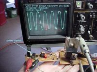
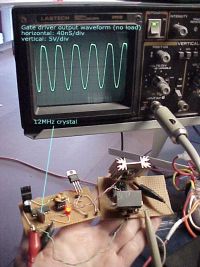
The first pic is a breadboarded driver, @ 13.56MHz (RC osc.) into an IRF510.
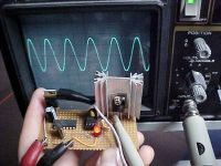
The second pic is the veroified driver, @ 12MHz (crystal) into an IRF510.
I bias the gate at 6V, and the resulting swing is about +14 to -2V.
The IRF510 will provide the gatedrive for a larger FET.


Re: smaller coils (and a 12MHz target)
Marko, Sun Oct 08 2006, 01:35PM
Yup, i'm afraid that for very high frequencies you'l have to goodbye the UCC's no matter your emotional devotions to them.
R. burnett used simple transistor push-pull to drive first class E stage, and it's not problematic at all since sinewave is fine for class E, and with resonant drive little power is required to get optimal drive.
Probably any small complementary pair would do.
Can you hook up the upper setup to an IRFP450 to see if it would work? =)
Re: smaller coils (and a 12MHz target)
ragnar, Sun Oct 08 2006, 10:56PM
Can you hook up the upper setup to an IRFP450 to see if it would work? =)
The gate charge of an IRFP450 is 75nC. The gate charge of an IRF510 is 5nC. It is not possible to swing 2600nF at 13.56MHz with a single UCCX7322.
Usings TWO UCCs with an 11:3 stepdown transformer with a resonating secondary and 30Vp/p across the primary, I found it impossible to exceed ~6.5MHz, even when the UCCs were heatsinked.
And even if a single IRFP450 could be driven at 13.56MHz with a single UCCX7322, that takes all the fun out of it, so I'd do it another way anyway
ragnar, Sun Oct 08 2006, 10:56PM
wrote ...
Yup, i'm afraid that for very high frequencies you'l have to goodbye the UCC's no matter your emotional devotions to them.
Never!! My emotional attachment absolutely and overtly requires me to discover the secrets to getting these drivers to work at stupid frequencies three orders of magnitude higher than they were intended for. I've already disclosed one of them; that you may only use the noninverting driver, UCCX7322 if you want half-reasonable waveforms and a close-to-50% duty cycle output for a 50% duty cycle input.Yup, i'm afraid that for very high frequencies you'l have to goodbye the UCC's no matter your emotional devotions to them.
wrote ...
R. burnett used simple transistor push-pull to drive first class E stage, and it's not problematic at all since...
At 4MHz with 12V drive, fine, yes. I don't have an easy way of getting a nice 12V drive to these little transistors at 13.56MHz. The CD4024B divider dies at 9.5MHz out (19MHz input).R. burnett used simple transistor push-pull to drive first class E stage, and it's not problematic at all since...
wrote ...
with resonant drive little power is required to get optimal drive.
I think you'd be surprised... I'm probably looking into losing at least 10W into the gate, and I haven't even started di/dt- and dv/dt-ing it all over the place yet.with resonant drive little power is required to get optimal drive.
wrote ...
Probably any small complementary pair would do.
Trust me, been there, done that, I found it too sensitive, unreliable.Probably any small complementary pair would do.
Can you hook up the upper setup to an IRFP450 to see if it would work? =)
The gate charge of an IRFP450 is 75nC. The gate charge of an IRF510 is 5nC. It is not possible to swing 2600nF at 13.56MHz with a single UCCX7322.
Usings TWO UCCs with an 11:3 stepdown transformer with a resonating secondary and 30Vp/p across the primary, I found it impossible to exceed ~6.5MHz, even when the UCCs were heatsinked.
And even if a single IRFP450 could be driven at 13.56MHz with a single UCCX7322, that takes all the fun out of it, so I'd do it another way anyway

Re: smaller coils (and a 12MHz target)
Marko, Mon Oct 09 2006, 10:03AM
Oh, I meant to drive '450 with with IRFP510's output
10W isn't really too much power, when you think what would it look like with hard drive at that frequency
IIRC richie needed about 5W at gate for his coil at 4Mhz.
Marko, Mon Oct 09 2006, 10:03AM
The gate charge of an IRFP450 is 75nC. The gate charge of an IRF510 is 5nC. It is not possible to swing 2600nF at 13.56MHz with a single UCCX7322.ž
Oh, I meant to drive '450 with with IRFP510's output

10W isn't really too much power, when you think what would it look like with hard drive at that frequency

IIRC richie needed about 5W at gate for his coil at 4Mhz.
Re: smaller coils (and a 12MHz target)
Steve Conner, Mon Oct 09 2006, 10:25AM
I was always amazed that Matt could get the UCC37322 to work at such high frequencies as he did. UCC's use a double output stage with MOSFETs and BJTs in parallel, and BJTs take a finite time to turn off, so I'd have expected huge amounts of shoot-through leading to overheating and destruction.
I'm thinking that he probably gets away with it as long as he draws little enough current that the MOSFET part of the output stage takes all the load and the BJTs don't conduct.
Firkragg: Even with resonant drive, you need to supply a fair amount of power to overcome losses in the MOSFET's gate resistance, since the gate electrode is made out of a poorly conducting crappy polysilicon. 10W of gate drive at 14MHz sounds in the ballpark, for an IRFP460 sized device, and I'd expect it to rise to 25-40W at 30MHz, at serious risk of burning out the gate structure.
It should still be considerably less than if you used hard drive and burnt 1/2*Cg*Vg^2 of energy at every cycle.
Re: smaller coils (and a 12MHz target)
Marko, Mon Oct 09 2006, 10:31AM
Soft switching helps them turn off.
With hard drivechips won't make more than 4-5Mhz with little load, and waveform would look gross anyway so it's better to turn it into real sine, while class E amp doesn't care about it much.
Marko, Mon Oct 09 2006, 10:31AM
Soft switching helps them turn off.
With hard drivechips won't make more than 4-5Mhz with little load, and waveform would look gross anyway so it's better to turn it into real sine, while class E amp doesn't care about it much.
Re: smaller coils (and a 12MHz target)
ragnar, Wed Oct 11 2006, 07:12AM
Here's the bastard-power-gatedriver-from-hell running well-synchronised at 12MHz, nominal 24V p/p.
Next I'll attempt to load it down with a FET.
ragnar, Wed Oct 11 2006, 07:12AM
Here's the bastard-power-gatedriver-from-hell running well-synchronised at 12MHz, nominal 24V p/p.
Next I'll attempt to load it down with a FET.


Re: smaller coils (and a 12MHz target)
WaveRider, Wed Oct 11 2006, 08:19AM
Hi BP.. That's the IXDD414? You certainly know how to torture those poor gate drive chips!! ;)
WaveRider, Wed Oct 11 2006, 08:19AM
Hi BP.. That's the IXDD414? You certainly know how to torture those poor gate drive chips!! ;)
Re: smaller coils (and a 12MHz target)
Steve Conner, Wed Oct 11 2006, 09:08AM
What supply voltage are you feeding it with at 12MHz? Did you say 24V? O_O
Steve Conner, Wed Oct 11 2006, 09:08AM
What supply voltage are you feeding it with at 12MHz? Did you say 24V? O_O
Re: smaller coils (and a 12MHz target)
Marko, Wed Oct 11 2006, 11:59AM
Why O_O? If driver can take it thet it's and advantage because less current will be pulled from it, as he uses a GDT anyway...
Marko, Wed Oct 11 2006, 11:59AM
Steve Conner wrote ...
What supply voltage are you feeding it with at 12MHz? Did you say 24V? O_O
What supply voltage are you feeding it with at 12MHz? Did you say 24V? O_O
Why O_O? If driver can take it thet it's and advantage because less current will be pulled from it, as he uses a GDT anyway...

Re: smaller coils (and a 12MHz target)
ragnar, Wed Oct 11 2006, 01:06PM
Hi WaveRider, Steve,
feeding them with 12V each, and input signals exactly 180 degrees out of phase (I found this quite tricky at 12MHz ) that's the output you see there...
Matching it into a FET is proving tricky, but I'm working on it
Edit: re gatedrivers link, been there before, but thanks anyway, the other guys will benefit =-D
ragnar, Wed Oct 11 2006, 01:06PM
Hi WaveRider, Steve,
feeding them with 12V each, and input signals exactly 180 degrees out of phase (I found this quite tricky at 12MHz
 ) that's the output you see there...
Matching it into a FET is proving tricky, but I'm working on it

Edit: re gatedrivers link, been there before, but thanks anyway, the other guys will benefit =-D
Re: smaller coils (and a 12MHz target)
Steve Conner, Wed Oct 11 2006, 01:06PM
O_O because internal losses due to charging and discharging the device's own capacitance (what makes the device "Die unloaded" I guess) increase as the square of the supply voltage.
Edit: found some good information on gate drivers
Steve Conner, Wed Oct 11 2006, 01:06PM
O_O because internal losses due to charging and discharging the device's own capacitance (what makes the device "Die unloaded" I guess) increase as the square of the supply voltage.
Edit: found some good information on gate drivers

Re: smaller coils (and a 12MHz target)
Avalanche, Wed Nov 08 2006, 03:11PM
Thought i'd dig up this thread instead of starting a new one, or pulling the HF gate drive off topic too much...
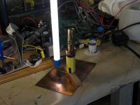
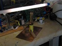
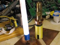
I suppose I can now claim to owning a 12Mhz sstc, because I've managed to light tubes.
Interesting thing is, I am base feeding the secondary with only 13.8 volts into the final class-e stage - yet managing to get a fairly strong electric field, but no sparks (can't even draw sparks, it's equivalent to just shorting the load out).
To make it work requires a heck of a topload, for plenty of capacitive coupling from the topload to the copper board below (which is connected to the source of the fet / ground). I'm not sure it can be classed as a true tesla coil, because there seem to be 2 high voltage nodes - on the 'ground' and on the topload. More like just a series LC circuit connected between the source and drain, with a 'less obvious' capacitor. I can't figure out how to ground it properly, because it's impossible to ground the resonator
Anyway I was quite impressed with what it could do, didn't expect it to do anything!
Avalanche, Wed Nov 08 2006, 03:11PM
Thought i'd dig up this thread instead of starting a new one, or pulling the HF gate drive off topic too much...
I suppose I can now claim to owning a 12Mhz sstc, because I've managed to light tubes.
Interesting thing is, I am base feeding the secondary with only 13.8 volts into the final class-e stage - yet managing to get a fairly strong electric field, but no sparks (can't even draw sparks, it's equivalent to just shorting the load out).
To make it work requires a heck of a topload, for plenty of capacitive coupling from the topload to the copper board below (which is connected to the source of the fet / ground). I'm not sure it can be classed as a true tesla coil, because there seem to be 2 high voltage nodes - on the 'ground' and on the topload. More like just a series LC circuit connected between the source and drain, with a 'less obvious' capacitor. I can't figure out how to ground it properly, because it's impossible to ground the resonator

Anyway I was quite impressed with what it could do, didn't expect it to do anything!


Re: smaller coils (and a 12MHz target)
Marko, Wed Nov 08 2006, 03:23PM
nice, but you are going to need a primary unless you are happy with lighting tubes from few cm's distance.
Only thing you can try is to use highest possible input voltage for your mosfet (yes 150 volts) to get most power you can from such high impedance.
Marko, Wed Nov 08 2006, 03:23PM
nice, but you are going to need a primary unless you are happy with lighting tubes from few cm's distance.
Only thing you can try is to use highest possible input voltage for your mosfet (yes 150 volts) to get most power you can from such high impedance.
Re: smaller coils (and a 12MHz target)
Avalanche, Wed Nov 08 2006, 03:30PM
 yeah I'm going to have to give in and use a primary on this coil...
It's also nowhere near class-e operation so i'm jumping the gun a bit by saying I have a working coil, that's just me. The mosfet is overheating big time, so I don't think I'll turn up the volts yet.
I'll eventually get base feeding to work properly, one day...
Avalanche, Wed Nov 08 2006, 03:30PM
 yeah I'm going to have to give in and use a primary on this coil...
 It's also nowhere near class-e operation so i'm jumping the gun a bit by saying I have a working coil, that's just me. The mosfet is overheating big time, so I don't think I'll turn up the volts yet.
I'll eventually get base feeding to work properly, one day...
Re: smaller coils (and a 12MHz target)
Avalanche, Sun Nov 12 2006, 06:53PM
48hr double post...
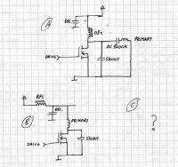
I'm not having much luck with using a primary. Using config 'B' from the picture below, I can get a tube to light again, but that's about all, no breakout. I've tried both methods below, and I'm not sure which is best. I think richie uses config 'A', but his site seems to be down still. So how is everyone hooking the primary up? I've drawn both methods I've tried so far, and I don't think I'm missing anything?
Another odd thing I am seeing is a 24Mhz signal between D-S when I put it under load. Could my whole setup be oscillating because I have added extra gate capacitance?
This thing's a nightmare


Re: smaller coils (and a 12MHz target)
Marko, Sun Nov 12 2006, 06:59PM
I used primary itself as RFC (b schematic). It seems to work as well as richie burnett design (amp separate from primary), only it needs good decoupling cap close to mosfet, and all inductance 'after' the cap counts as your primary leakage inductance.
Your coil must be mistuned if you aren't getting any sparks, no matter of class-e tunage.
Use long wire to move the breakout point away from topload.
What power/voltage are you putting into coil?
With my config I was getting 4cm sparks with some 20V in.
PS. you may sometimes double-post as this is only going to make steve conner post something funny and merge threads..
Just kidding, don't do it actually..
Marko, Sun Nov 12 2006, 06:59PM
I used primary itself as RFC (b schematic). It seems to work as well as richie burnett design (amp separate from primary), only it needs good decoupling cap close to mosfet, and all inductance 'after' the cap counts as your primary leakage inductance.
Your coil must be mistuned if you aren't getting any sparks, no matter of class-e tunage.
Use long wire to move the breakout point away from topload.
What power/voltage are you putting into coil?
With my config I was getting 4cm sparks with some 20V in.
PS. you may sometimes double-post as this is only going to make steve conner post something funny and merge threads..

Just kidding, don't do it actually..
Re: smaller coils (and a 12MHz target)
Avalanche, Mon Nov 13 2006, 12:11AM
It must just me my mistuned coil then... although I am only putting in 13.8 volts. I'll just use config 'B' then and try a decent decoupling cap. And a tuned coil.
I won't make a habit of double posting, but I think it was legit (or at least bordering on )
)
Avalanche, Mon Nov 13 2006, 12:11AM
It must just me my mistuned coil then... although I am only putting in 13.8 volts. I'll just use config 'B' then and try a decent decoupling cap. And a tuned coil.
I won't make a habit of double posting, but I think it was legit (or at least bordering on
 )
)Re: smaller coils (and a 12MHz target)
Marko, Mon Nov 13 2006, 12:26PM
Posting 48hrs after last post is allowed, but before that isn't.
Decoupling cap must be polypropylene, and possibly something better than single metallization (high continuous currents) for low ESR.
Other types heat up like nuts, change capacitance and frequently blow everything up after detuning away enough from class E.
Are you using feedback or oscillator to drive the coil?
Re: smaller coils (and a 12MHz target)
Avalanche, Mon Nov 13 2006, 12:41PM
I'm using a crystal oscillator to drive it.
I'll have to get a few decent capacitors I guess, I'm just using whatever I can find at the moment. Thanks for the help!
Avalanche, Mon Nov 13 2006, 12:41PM
I'm using a crystal oscillator to drive it.
I'll have to get a few decent capacitors I guess, I'm just using whatever I can find at the moment. Thanks for the help!
Re: smaller coils (and a 12MHz target)
Steve Conner, Mon Nov 13 2006, 12:47PM
We do take the no-bumping rule seriously. I might "Post something funny" but, along with all the other moderators, I keep a tally of how many double posts each user has to their name, and too many gets you pwn't.
Steve Conner, Mon Nov 13 2006, 12:47PM
We do take the no-bumping rule seriously. I might "Post something funny" but, along with all the other moderators, I keep a tally of how many double posts each user has to their name, and too many gets you pwn't.
Re: smaller coils (and a 12MHz target)
Marko, Mon Nov 13 2006, 08:42PM
I think it's really easy to set up antenna feedback, just use a 74HC14 or something similar in place of your crystal.
You'l have problems with startup, though, so <ou need some simple oscillator to 'ping' the system while it's 'out of lock'.
You can maybe just keep the existing crystal osc and weaken it's signal enough that antenna easily overrides it.
If you plan to continue using oscillator, you'l have to slowly remove turns from secondary until you get best tune.
You can also use a trick with telescopic whip antenna topload, wich you can pull in or out for finetune.
Marko, Mon Nov 13 2006, 08:42PM
Avalanche wrote ...
I'm using a crystal oscillator to drive it.
I'll have to get a few decent capacitors I guess, I'm just using whatever I can find at the moment. Thanks for the help!
I'm using a crystal oscillator to drive it.
I'll have to get a few decent capacitors I guess, I'm just using whatever I can find at the moment. Thanks for the help!
I think it's really easy to set up antenna feedback, just use a 74HC14 or something similar in place of your crystal.
You'l have problems with startup, though, so <ou need some simple oscillator to 'ping' the system while it's 'out of lock'.
You can maybe just keep the existing crystal osc and weaken it's signal enough that antenna easily overrides it.
If you plan to continue using oscillator, you'l have to slowly remove turns from secondary until you get best tune.
You can also use a trick with telescopic whip antenna topload, wich you can pull in or out for finetune.

Re: smaller coils (and a 12MHz target)
ragnar, Wed Nov 15 2006, 03:13AM
The fact my signal generator goes nuts when I run this coil really, really isn't helping, BUT:
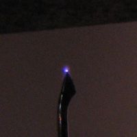
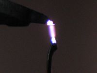
Here's first light from the 13.56MHz coil:
Very hot lil arcs... but I'm drawing 2A at 22V to get this to happen -- I think it'll be hopeless until I can get the class-E tuned correctly... and stop the siggen going crazy every time I approach Fres. =D
Still, it makes sparks!


Re: smaller coils (and a 12MHz target)
..., Wed Nov 15 2006, 05:44AM
I can concur that frequency generator going crazy when you hit resonance is very much not cool. Like hot as plasma not cool
I blew out at least one fullbridge cos of that I had a bridge made of irfp250's and was running ~50v in, sweeping the frequency around (I needed a finer knob on my sig gen) when I managed to get it really in tune, but then the gen went crazy and sent it far enough out of tune to blow up the bridge in all of the flaming glory you love (although I had the foresight to include a fuse as to prevent the ripping the cord out of the wall)
Hmm, only 40w for like 1mm... You are approaching my all time record of 5" off 1.4kw
..., Wed Nov 15 2006, 05:44AM
I can concur that frequency generator going crazy when you hit resonance is very much not cool. Like hot as plasma not cool

I blew out at least one fullbridge cos of that
 I had a bridge made of irfp250's and was running ~50v in, sweeping the frequency around (I needed a finer knob on my sig gen) when I managed to get it really in tune, but then the gen went crazy and sent it far enough out of tune to blow up the bridge in all of the flaming glory you love (although I had the foresight to include a fuse as to prevent the ripping the cord out of the wall)
Hmm, only 40w for like 1mm... You are approaching my all time record of 5" off 1.4kw

Re: smaller coils (and a 12MHz target)
ragnar, Wed Nov 15 2006, 07:50AM
I tweaked the shunt capacitor to 63pF (40kV :P) which makes the coil a lot more stable. It's interesting how big the shift is (~1MHz) between drawing an arc from the coil, and then tuning it to emit corona by itself. The system really has to be started at a different frequency from where you intend to run it.
The first breakout and corona has to be coaxed out with a knifeblade or similar. I also increased the drive voltage to 32V and it's drawing ~1.4A in these pics. The class-E operation seems almost spot on with the new capacitor(s), but something's still not quite right -- my gate waveform is much spikier, with a much lower duty (as a result of me putting in a UCC37321 instead of UCC37322 in my signal generator), and only hits about 10V peak.
To get a proper 50/50 duty cycle I'm going to try and go for a 74HC14 oscillator which won't drop into weird modes (even when grounded, pin2, pin9 and pin14 on the PLL chip is going nuts just by being nearby)... and I guess when I want audio modulation, I'm going to have to do it properly (class-G or class-H modulator)...
Even though there's a long way to go, first (and second) light is very rewarding!
This is one HOT lil' breakout.
What do you guys think?
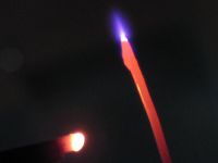

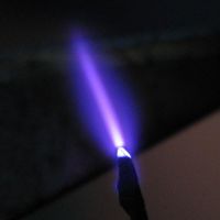
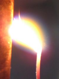
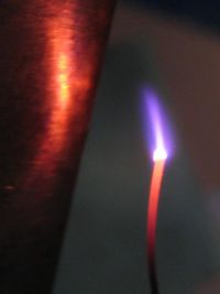
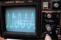
This is the DS waveform, 40nS/20V per div., supply voltage is 32V.
ragnar, Wed Nov 15 2006, 07:50AM
I tweaked the shunt capacitor to 63pF (40kV :P) which makes the coil a lot more stable. It's interesting how big the shift is (~1MHz) between drawing an arc from the coil, and then tuning it to emit corona by itself. The system really has to be started at a different frequency from where you intend to run it.
The first breakout and corona has to be coaxed out with a knifeblade or similar. I also increased the drive voltage to 32V and it's drawing ~1.4A in these pics. The class-E operation seems almost spot on with the new capacitor(s), but something's still not quite right -- my gate waveform is much spikier, with a much lower duty (as a result of me putting in a UCC37321 instead of UCC37322 in my signal generator), and only hits about 10V peak.
To get a proper 50/50 duty cycle I'm going to try and go for a 74HC14 oscillator which won't drop into weird modes (even when grounded, pin2, pin9 and pin14 on the PLL chip is going nuts just by being nearby)... and I guess when I want audio modulation, I'm going to have to do it properly (class-G or class-H modulator)...
Even though there's a long way to go, first (and second) light is very rewarding!
This is one HOT lil' breakout.
What do you guys think?


This is the DS waveform, 40nS/20V per div., supply voltage is 32V.
Re: smaller coils (and a 12MHz target)
WaveRider, Wed Nov 15 2006, 08:53AM
BP.. It's outstanding work!
Perhaps if you made all the wiring as compact as possible (short leads, no "big" loops where your primary connects to PCB, etc.) and shielded everything, your bench instruments should not go crazy (I noticed this too before I put my coil in a faraday cage.) You are no doubt radiating significant harmonic power as well as possibly inductively coupling into power-supply leads... Just a thought....
EMC...it's not just for breakfast anymore!
Cheers,
Bill
WaveRider, Wed Nov 15 2006, 08:53AM
BP.. It's outstanding work!
Perhaps if you made all the wiring as compact as possible (short leads, no "big" loops where your primary connects to PCB, etc.) and shielded everything, your bench instruments should not go crazy (I noticed this too before I put my coil in a faraday cage.) You are no doubt radiating significant harmonic power as well as possibly inductively coupling into power-supply leads... Just a thought....
EMC...it's not just for breakfast anymore!

Cheers,
Bill
Re: smaller coils (and a 12MHz target)
Avalanche, Wed Nov 15 2006, 09:01AM
Amazing work, love it!
That breakout is scary, looks like there's a lot of rf current going into the streamer
Avalanche, Wed Nov 15 2006, 09:01AM
Amazing work, love it!
That breakout is scary, looks like there's a lot of rf current going into the streamer

Re: smaller coils (and a 12MHz target)
ragnar, Wed Nov 15 2006, 09:32AM
Thanks Peter, Avalanche, WaveRider =)
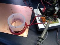
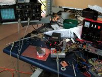
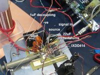
In these pics here, you can see the output board from close up:
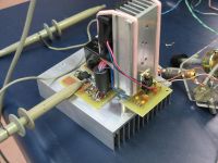
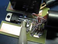
My primary is connected straight to the drain, i.e.:
+VE >> PRIMARY >> MOSFET >> GND
On that circuit board, the DRAIN and +VE are the big pads on the left and right of the FET, respectively. I've snuggled the decoupling cap in there as best as I can, and you can see where the big negative pad connects straight to SOURCE.
I could connect the primary straight to the heatsink underneath the positive pad (not using insulators, for now, which greatly helps with removing heat from the TO-220 package).
It's interesting to note I'm getting ~100V peaks on the drain with a 32V supply. The IRF730 is a 400V FET, so if I can keep it well enough in tune, I'd consider tripling the supply voltage =D You guys can flame me later.
I should also play around with the turns and coupling on the primary -- I'm sure that two turns isn't optimal.
Keep the ideas coming, thanks again guys =)
ragnar, Wed Nov 15 2006, 09:32AM
Thanks Peter, Avalanche, WaveRider =)
In these pics here, you can see the output board from close up:


My primary is connected straight to the drain, i.e.:
+VE >> PRIMARY >> MOSFET >> GND
On that circuit board, the DRAIN and +VE are the big pads on the left and right of the FET, respectively. I've snuggled the decoupling cap in there as best as I can, and you can see where the big negative pad connects straight to SOURCE.
I could connect the primary straight to the heatsink underneath the positive pad (not using insulators, for now, which greatly helps with removing heat from the TO-220 package).
It's interesting to note I'm getting ~100V peaks on the drain with a 32V supply. The IRF730 is a 400V FET, so if I can keep it well enough in tune, I'd consider tripling the supply voltage =D You guys can flame me later.
I should also play around with the turns and coupling on the primary -- I'm sure that two turns isn't optimal.
Keep the ideas coming, thanks again guys =)
Re: smaller coils (and a 12MHz target)
Steve Conner, Wed Nov 15 2006, 11:00AM
Wow, excellent work BP!

Steve Conner, Wed Nov 15 2006, 11:00AM
Wow, excellent work BP!


Re: smaller coils (and a 12MHz target)
ragnar, Sat Nov 18 2006, 12:10PM
[Forgive the double post -- I hit 'submit' twice -- my apologies. ]
]
ragnar, Sat Nov 18 2006, 12:10PM
[Forgive the double post -- I hit 'submit' twice -- my apologies.
 ]
]Re: smaller coils (and a 12MHz target)
ragnar, Sat Nov 18 2006, 12:11PM
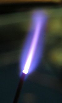
I raised the secondary by putting two tiny C-shaped aluminium heatsinks over the primary to sit it on, and now he resonates at 12.7MHz. I also get a higher voltage (or at least, longer breakout) at the top of the coil. The plasma appearance is just breathtaking at such high frequencies -- it looks less and less like an electrical discharge and more and more like a tiny blowtorch flame.
The wire forming my secondary (0.5mm, or 0.02in)gets ridiculously hot after a few minutes of operation... considering the skin depth (or lack of!) in copper at 12+MHz, I shouldn't be surprised.. If I had thicker wire, I'd like to rewind it with more turns and a smaller diameter.
I will also adjust primary turns and consider enclosing in a cage.


Re: smaller coils (and a 12MHz target)
Avalanche, Sat Nov 18 2006, 01:24PM
Nice pictures! How does the discharge compare to your 'lower' frequency class-e coils (in terms of appearance/impressiveness more than size)? I'm seriously considering cutting my frequency in half with my current setup, as it should be easy to get 6Mhz at quite a bit of power with this lot.
Re: smaller coils (and a 12MHz target)
Marko, Sat Nov 18 2006, 01:48PM
How long is that spark BP?
When I lower my power (1,5Mhz) to few watts I can get a 1cm spark looking like that;
My problem is that I usually don't use enough filter caps so spark buzzes, but if power is very low it just hisses faintly.
Marko, Sat Nov 18 2006, 01:48PM
How long is that spark BP?
When I lower my power (1,5Mhz) to few watts I can get a 1cm spark looking like that;
My problem is that I usually don't use enough filter caps so spark buzzes, but if power is very low it just hisses faintly.
Re: smaller coils (and a 12MHz target)
ragnar, Sat Nov 18 2006, 01:55PM
The angle of the photo doesn't help, but that spark is ~9-10mm in length.
When the signal generator is stable, the arc makes NO noise. In still air it does NOT even appear to move.
If you didn't already see them, the pics from my 6.5MHz coil can be found here:
http://www.infringingwebsite.com/matt/6.5mhz/
Notice how in all the pics, although the edges of the discharge are a very fuzzy plasma glow, it *still* branches out into 'streamers' of some description.
The 6.5MHz discharge still retains a lightning-like appearance that causes hissing/rippling noises, which is why I set my aspirations at 13.56MHz.
As I coax more and more power from the coil (I need to get my Variac operational for this), things will get more interesting, and I think the rippling noises will start again.
Re: smaller coils (and a 12MHz target)
Marko, Sat Nov 18 2006, 02:58PM
Yeah, exactly same thing for me at 1,5Mhz
It looks like a small sword and doesn't move around.
Except I could never take so good pics of it
Marko, Sat Nov 18 2006, 02:58PM
When the signal generator is stable, the arc makes NO noise. In still air it does NOT even appear to move.
Yeah, exactly same thing for me at 1,5Mhz

It looks like a small sword and doesn't move around.
Except I could never take so good pics of it

Re: smaller coils (and a 12MHz target)
teravolt, Sat Nov 18 2006, 08:55PM
what is the distance it takes to light a florecent lamp? I use florecent lamps to mesure field srength
teravolt, Sat Nov 18 2006, 08:55PM
what is the distance it takes to light a florecent lamp? I use florecent lamps to mesure field srength
Re: smaller coils (and a 12MHz target)
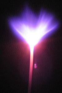
ragnar, Mon Nov 20 2006, 09:52AM
Well, I'll admit this isn't very rewarding. I rewound the secondary on thinner 26mm teflon PFA tube, and the secondary resonated at around the same frequency but had about three-four times the turncount. I increased my primary to three turns, and now use direct drive from two IXDDs onto the gate.
It draws a little more current, the spark is a little bigger, but still a great deal of heating of the FET and the IXDDs.
I worry that the on-resistance of the IRF730 is a wee bit too big to make this a worthwhile endeavour... but if I parallel them, the output capacitance might become too big. =P
Ideas? =P
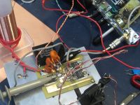


Re: smaller coils (and a 12MHz target)
Steve Conner, Mon Nov 20 2006, 05:31PM
If you're looking for ideas: why not use two IRF730s in push-pull?
Steve Conner, Mon Nov 20 2006, 05:31PM
If you're looking for ideas: why not use two IRF730s in push-pull?

Re: smaller coils (and a 12MHz target)
WaveRider, Mon Nov 20 2006, 06:05PM
Or perhaps use a higher driving voltage (lower drain current...I use 100-115V drain supply...of course, this may mean more primary turns to increase the coil primary feedpoint impedance suitably).
How much current is drawn from the DC supply (in the MOSFET drain circuit)? Also, where is the drain RF choke (is there one? didnt see one in your picture)..
Note that all the "flying leads" will load the circuit considerably at 13.56 MHz, too..
Re: smaller coils (and a 12MHz target)
Marko, Mon Nov 20 2006, 08:45PM
Primary is obivously used as a choke, same as me and steve ward did.
That mosfet is quite small indeed; you can't actually push more than about an amp in that conditions without blowing it up.
You should use more primary turns and higher supply voltage to make better use of your mosfet.
Mosfet also wastes quite a lot of power here (hope it's not more than the spark itself) so you must keep a large heatsink on it.
One thing that could also be tried is paralelling a handful of small mosfet's, maybe something like IRFU410A (osram saver bulb mosfets); I happemn to have ton over here.
They are puny in their ratings but switching times are great, and due to high ON resistance paralelling shouldn't be a problem.
I would also like to see BP's multi-coil in performance at one point here. It should be much more potent at those frequencies than 'normal' coils and much less wasteful in copper...
Re: smaller coils (and a 12MHz target)
ragnar, Tue Nov 21 2006, 01:05AM
The flying leads are probably pretty bad, but I thought that they'd be OK since power is fairly well decoupled.
I presume I can't use an RF choke with my current setup?
Push/pull is a really good idea, thanks. =)
ragnar, Tue Nov 21 2006, 01:05AM
The flying leads are probably pretty bad, but I thought that they'd be OK since power is fairly well decoupled.
I presume I can't use an RF choke with my current setup?
Push/pull is a really good idea, thanks. =)

Re: smaller coils (and a 12MHz target)
WaveRider, Tue Nov 21 2006, 03:43PM
BP.. If you are feeding the primary by making it part of the drain circuit, then your heat sink must have a considerable RF potential on it (adding capacitance to your drain circuit...which may not be a bad thing). The consequences of this are the obvious safety issues, but also it can cause coupling (and possbly lots of harmonic radiation...which can possibly cause extra loading and heating of your transistor).
Also, if the heatsink has a high RF potential, all those power leads and coax shialds can couple to the heatsink field and will act like antennas... My suggestion would to be to keep that big block of metal at RF earth potential. Provided I am deciphering your circuit correctly, I am damn impressed with your ability to get the circuit to work!!!
Also, I should clear up a misconception about the primary winding in the drain circuit. It is _not_ a choke. If no decoupling cap is used at VDD, it will sit at a non-zero RF potential and your power leads will behave like transmission lines/radiators. Also, the dynamics of the circuit are quite different using this setup as opposed to the classic Class-E setup with the RFC. The choke (big red thing in this pic) in the classic class-E amp makes the DC source look like a current source at RF (a Norton transformation, in technical terms). There is no such beast in the drain-connected primary as shown.
And yes, push pull is a good idea, but it requires careful design to keep the phasings correct.
Keep up the astounding work!!
Re: smaller coils (and a 12MHz target)
ragnar, Tue Nov 21 2006, 11:44PM
Hehe, you know, I just found my scope probe and ground lead was getting really hot every time I poked the thing. Yowch! No more!
ragnar, Tue Nov 21 2006, 11:44PM
Hehe, you know, I just found my scope probe and ground lead was getting really hot every time I poked the thing. Yowch! No more!
Re: smaller coils (and a 12MHz target)
Marko, Wed Nov 22 2006, 12:41AM
I think that only real problem here is slowness mosfet's swiching itself, and there's little that can be done for it.
Regarding 'no choke' topology, I managed to push 10+cm spark out of 8cm high coil so I think it works pretty well.
One good decoupling cap is a must and there should be no pproblems with this.
Although I don't think it as a big problem, you can always put a little insulator between that heatsink and fet...
Re: smaller coils (and a 12MHz target)
ragnar, Wed Nov 22 2006, 02:29AM
Lots of harmonic radiation is definitely there -- the radio goes silent whenever I turn this on, regardless of what station, and regardless of what frequency I drive it at. =P
I wasn't so worried about the heatsink having RF on it... but at this stage, I'll try putting some mica and grease on. Do I dare ground the heatsink?

 hehe
hehe
Does your setup look something like this:?
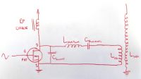
How do you calculate or estimate the value of the RF choke, Lmatch and Cblocking? Or is the RF choke uncritical as it'll just allow more/less current through? Have I even got the arrangement of Ls and Cs correct? :P
(Well, it seemed like a good idea at the time, your honour. And your honour, I swear that those outputs were sinewaves last time I checked, too.)
-----
On another note, looking through MOSFET datasheets today, I notice that:
IRF730 output capacitance = 150pF
IRFP450 output capacitance = 720pF
IRFP450LC output capacitance = 320pF
Since I'm adding 50-63pF of my own capacitance across DS, do I presume then that there's no way I can use FETs with an output capacitance larger than, say ~200pF? Or does that change when I use a proper network to couple the primary?
cheers,
Matt
ragnar, Wed Nov 22 2006, 02:29AM
wrote ...
BP.. If you are feeding the primary by making it part of the drain circuit, then your heat sink must have a considerable RF potential on it (adding capacitance to your drain circuit...which may not be a bad thing). The consequences of this are the obvious safety issues, but also it can cause coupling (and possbly lots of harmonic radiation...which can possibly cause extra loading and heating of your transistor).
I regret that I'm doing just that, which is probably unforgiveable at > 1MHz, and I feel secretly very lucky that I can get spark output at all.BP.. If you are feeding the primary by making it part of the drain circuit, then your heat sink must have a considerable RF potential on it (adding capacitance to your drain circuit...which may not be a bad thing). The consequences of this are the obvious safety issues, but also it can cause coupling (and possbly lots of harmonic radiation...which can possibly cause extra loading and heating of your transistor).
Lots of harmonic radiation is definitely there -- the radio goes silent whenever I turn this on, regardless of what station, and regardless of what frequency I drive it at. =P
I wasn't so worried about the heatsink having RF on it... but at this stage, I'll try putting some mica and grease on. Do I dare ground the heatsink?
wrote ...
Also, if the heatsink has a high RF potential, all those power leads and coax shialds can couple to the heatsink field and will act like antennas... My suggestion would to be to keep that big block of metal at RF earth potential.
Mm, after noticing the oscilloscope-ground-lead heating issue, I figured that the pickup is horrendous even many inches away. Ooh, ooh, so if I make my heatsink the counterpoise for the TC... then it's at RF earth potential? Also, if the heatsink has a high RF potential, all those power leads and coax shialds can couple to the heatsink field and will act like antennas... My suggestion would to be to keep that big block of metal at RF earth potential.

 hehe
hehe wrote ...
If no decoupling cap is used at VDD, it will sit at a non-zero RF potential and your power leads will behave like transmission lines/radiators.
I'm beginning to feel that 1uF of decoupling isn't enough, and I should be using a variety of decouplers, like ceramic, film and electrolytic all in parallel.If no decoupling cap is used at VDD, it will sit at a non-zero RF potential and your power leads will behave like transmission lines/radiators.
wrote ...
Also, the dynamics of the circuit are quite different using this setup as opposed to the classic Class-E setup with the RFC. The choke (big red thing in this pic) in the classic class-E amp makes the DC source look like a current source at RF (a Norton transformation, in technical terms). There is no such beast in the drain-connected primary as shown.
Also, the dynamics of the circuit are quite different using this setup as opposed to the classic Class-E setup with the RFC. The choke (big red thing in this pic) in the classic class-E amp makes the DC source look like a current source at RF (a Norton transformation, in technical terms). There is no such beast in the drain-connected primary as shown.
Does your setup look something like this:?

How do you calculate or estimate the value of the RF choke, Lmatch and Cblocking? Or is the RF choke uncritical as it'll just allow more/less current through? Have I even got the arrangement of Ls and Cs correct? :P
wrote ...
And yes, push pull is a good idea, but it requires careful design to keep the phasings correct.
Often when I need to split a signal, the logic isn't fast enough, or my oscilloscope is too crap to accurately draw two waveforms in sync (as in I twiddle the trigger and dual traces move left/right in opposite directions), I've really got no way of adding delay to compensate for slow logic. So what I do is make a little transformer like so:And yes, push pull is a good idea, but it requires careful design to keep the phasings correct.
(Well, it seemed like a good idea at the time, your honour. And your honour, I swear that those outputs were sinewaves last time I checked, too.)
-----
On another note, looking through MOSFET datasheets today, I notice that:
IRF730 output capacitance = 150pF
IRFP450 output capacitance = 720pF
IRFP450LC output capacitance = 320pF
Since I'm adding 50-63pF of my own capacitance across DS, do I presume then that there's no way I can use FETs with an output capacitance larger than, say ~200pF? Or does that change when I use a proper network to couple the primary?
cheers,
Matt
Re: smaller coils (and a 12MHz target)
WaveRider, Wed Nov 22 2006, 09:38AM
Hi BP,
You are no doubt emitting lots of harmonics (for the FM radio, there will be harmonics at 108.48MHz and 94.92 MHz...both in the FM broadcast band).. You are evidently overloading the frontend of the radio receiver, rendering it insensitive to any station.
Yes! Ground that heatsink! If you make another PCB, use a double sided one. Keep one side as the ground plane and connections on the other. I usually mount the components on the circuit trace side. This minimises drilling. If you have ground traces on the circuit side, put lots of vias (1 every 2 cms or so) to the ground plane on the other side. Keep all connections as short as possible and keep power leads away from air-core coils (where they can couple easily). Mount heatsinks directly to the ground-plane side of the circuit board to minimise RF drops across inductive paths (keeping the heatsink at RF ground). The mica washer transistor mount will add a little capacitance, but if you are careful about eliminating inductive paths to PCB ground plane, there should be no troublesome VHF/UHF resonances.
Beware of self-resonances. Try to keep decoupling caps in the range of 0.5-1 ohm reactance at your operating frequency. 0.01uF should be plenty for your frequency range. Keep the cap leads SHORT!! 1 ohm inductive reactance is produced with 10nH...if this inductance is present in the 0.01uF cap leads and the cap itself, it will resonate, giving unpredictable results... I would suggest the smaller cap.
Yep, it looks similar to that circuit. I also have a variable capacitor across the primary for tuning.
The choice of Lmatch and Cblocking is a bit hit and miss because the it is difficult to calculate the loading from the arc. It generally has to experimentally determined. I started off assuming thet the resonator Q was about 10-20 with arc loading. Assuming that I wanted the real part of the feedpoint impedance to be around 50 ohms (chosen partly for "sentimental" reasons as well as allowing me to use a smaller variable capacitor for tuning). Generally the total inductive reactance of the output circuit should be about 5-8 times the load-line impedance of the transistor. (My case: 100V, 2.2A -> load-line resistance is about 0.5 * 100 / 2.2 = 22 ohms) Including the coil primary and Lmatch, total inductive reactance is about 100 ohms... In practice, my coil Lmatch gives best performance with about 60-70 ohms reactance at my operating frequency. This can be adjusted with the variable cap connected across the primary anyway. The variable cap also assists in transforming the real part of the impedance to a suitable value....when you vary the spark power level, the feedpoint resistance changes.. match can be (almost) restored by adjusting the variable cap. In short, settle on some starting values for Lmatch and Cblocking, Ctune and make an estimate of the primary feedpoint inductance. (I had the benefit of using an advanced simulation to make my estimates.)
The RF choke is simple... A good rule of thumb is to keep its reactance about 10-20 times the load-line resistance (500 ohms or so). 5 or 6 uH should be enough in your case. Don't overdo it tho'.. You don't want your choke to resonate. Use a powdered iron RF toroid core (no ferrite, Amidon mix 2 or 7 or equivalent should work fine).
There is nothing wrong with your topology, as long as you can get a reasonably good match and the transistor switching timing is correct. The only disadvantage is you have the DC supply present on the primary...this could make tuning difficult if you wanted to add a parallel tuning capacitor to the primary.
At your frequency...in the absence of advanced driver chips...transformer splitting is a great idea. Just make sure the driving circuit can supply enough power to prevent gate-drive "sag" when operating the final PA at full power.
The drain cap affects the coupling to the output circuit. Larger drain cap = lower coupling to output. Hence, by scaling the impedance looking into your matching network, you can counteract somewhat the effect of extra capacitance in the drain circuit. You may lose good class-E operation, but as long as your transistor runs reasonably efficiency and stays cool, who cares. Once you get proper class-E operation in one situation, you lose it if you change power level or change toploads. I found that as long as the transistor switches when it is subjected to Vdrain < 0.15 * VDD, it continues to run fairly cool and generates good power output. In fact, I can run what looks like class-B for a few seconds and get about 350 watts. Operating in its "near class-e" mode, it generates about 220 watts and will run all day in CW mode with no problems...
Hope my long-winded discourse is of some help. In short, by using ground-planes, metal enclosures and fine wire-mesh faraday cages, you will improve TC performance as well as reducing drastically "EM pollution" in your lab.
WaveRider, Wed Nov 22 2006, 09:38AM
Lots of harmonic radiation is definitely there -- the radio goes silent whenever I turn this on, regardless of what station, and regardless of what frequency I drive it at. =P
Hi BP,
You are no doubt emitting lots of harmonics (for the FM radio, there will be harmonics at 108.48MHz and 94.92 MHz...both in the FM broadcast band).. You are evidently overloading the frontend of the radio receiver, rendering it insensitive to any station.
I wasn't so worried about the heatsink having RF on it... but at this stage, I'll try putting some mica and grease on. Do I dare ground the heatsink?
Yes! Ground that heatsink! If you make another PCB, use a double sided one. Keep one side as the ground plane and connections on the other. I usually mount the components on the circuit trace side. This minimises drilling. If you have ground traces on the circuit side, put lots of vias (1 every 2 cms or so) to the ground plane on the other side. Keep all connections as short as possible and keep power leads away from air-core coils (where they can couple easily). Mount heatsinks directly to the ground-plane side of the circuit board to minimise RF drops across inductive paths (keeping the heatsink at RF ground). The mica washer transistor mount will add a little capacitance, but if you are careful about eliminating inductive paths to PCB ground plane, there should be no troublesome VHF/UHF resonances.
I'm beginning to feel that 1uF of decoupling isn't enough, and I should be using a variety of decouplers, like ceramic, film and electrolytic all in parallel.
Beware of self-resonances. Try to keep decoupling caps in the range of 0.5-1 ohm reactance at your operating frequency. 0.01uF should be plenty for your frequency range. Keep the cap leads SHORT!! 1 ohm inductive reactance is produced with 10nH...if this inductance is present in the 0.01uF cap leads and the cap itself, it will resonate, giving unpredictable results... I would suggest the smaller cap.
Does your setup look something like this:?
How do you calculate or estimate the value of the RF choke, Lmatch and Cblocking? Or is the RF choke uncritical as it'll just allow more/less current through? Have I even got the arrangement of Ls and Cs correct? :P
Yep, it looks similar to that circuit. I also have a variable capacitor across the primary for tuning.
The choice of Lmatch and Cblocking is a bit hit and miss because the it is difficult to calculate the loading from the arc. It generally has to experimentally determined. I started off assuming thet the resonator Q was about 10-20 with arc loading. Assuming that I wanted the real part of the feedpoint impedance to be around 50 ohms (chosen partly for "sentimental" reasons as well as allowing me to use a smaller variable capacitor for tuning). Generally the total inductive reactance of the output circuit should be about 5-8 times the load-line impedance of the transistor. (My case: 100V, 2.2A -> load-line resistance is about 0.5 * 100 / 2.2 = 22 ohms) Including the coil primary and Lmatch, total inductive reactance is about 100 ohms... In practice, my coil Lmatch gives best performance with about 60-70 ohms reactance at my operating frequency. This can be adjusted with the variable cap connected across the primary anyway. The variable cap also assists in transforming the real part of the impedance to a suitable value....when you vary the spark power level, the feedpoint resistance changes.. match can be (almost) restored by adjusting the variable cap. In short, settle on some starting values for Lmatch and Cblocking, Ctune and make an estimate of the primary feedpoint inductance. (I had the benefit of using an advanced simulation to make my estimates.)
The RF choke is simple... A good rule of thumb is to keep its reactance about 10-20 times the load-line resistance (500 ohms or so). 5 or 6 uH should be enough in your case. Don't overdo it tho'.. You don't want your choke to resonate. Use a powdered iron RF toroid core (no ferrite, Amidon mix 2 or 7 or equivalent should work fine).
There is nothing wrong with your topology, as long as you can get a reasonably good match and the transistor switching timing is correct. The only disadvantage is you have the DC supply present on the primary...this could make tuning difficult if you wanted to add a parallel tuning capacitor to the primary.
Often when I need to split a signal, the logic isn't fast enough, or my oscilloscope is too crap to accurately draw two waveforms in sync (as in I twiddle the trigger and dual traces move left/right in opposite directions), I've really got no way of adding delay to compensate for slow logic. So what I do is make a little transformer like so
At your frequency...in the absence of advanced driver chips...transformer splitting is a great idea. Just make sure the driving circuit can supply enough power to prevent gate-drive "sag" when operating the final PA at full power.
Since I'm adding 50-63pF of my own capacitance across DS, do I presume then that there's no way I can use FETs with an output capacitance larger than, say ~200pF? Or does that change when I use a proper network to couple the primary?
The drain cap affects the coupling to the output circuit. Larger drain cap = lower coupling to output. Hence, by scaling the impedance looking into your matching network, you can counteract somewhat the effect of extra capacitance in the drain circuit. You may lose good class-E operation, but as long as your transistor runs reasonably efficiency and stays cool, who cares. Once you get proper class-E operation in one situation, you lose it if you change power level or change toploads. I found that as long as the transistor switches when it is subjected to Vdrain < 0.15 * VDD, it continues to run fairly cool and generates good power output. In fact, I can run what looks like class-B for a few seconds and get about 350 watts. Operating in its "near class-e" mode, it generates about 220 watts and will run all day in CW mode with no problems...
Hope my long-winded discourse is of some help. In short, by using ground-planes, metal enclosures and fine wire-mesh faraday cages, you will improve TC performance as well as reducing drastically "EM pollution" in your lab.
Re: smaller coils (and a 12MHz target)
Steve Conner, Wed Nov 22 2006, 12:02PM
Thanks for the great tutorial WaveRider!
BP: As you go up in frequency, you eventually reach a point where the MOSFET's own output capacitance is as much as you need, and ultimately more than you'd like, for proper Class-E operation. So you don't need the external drain cap any longer. The capacitance between the FET's drain tab and the heatsink through the insulating washer starts to be a problem about then. One that I noticed you elegantly solved by leaving the whole heatsink live with RF
Steve Conner, Wed Nov 22 2006, 12:02PM
Thanks for the great tutorial WaveRider!

BP: As you go up in frequency, you eventually reach a point where the MOSFET's own output capacitance is as much as you need, and ultimately more than you'd like, for proper Class-E operation. So you don't need the external drain cap any longer. The capacitance between the FET's drain tab and the heatsink through the insulating washer starts to be a problem about then. One that I noticed you elegantly solved by leaving the whole heatsink live with RF

Re: smaller coils (and a 12MHz target)
ragnar, Sat Nov 25 2006, 12:21PM
WaveRider, you have my gratitude. Your "long winded discourse" goes into wonderful detail -- I feel very lucky to get such personal advice, thankyou.
I may be off-forum for a few days, but the first thing I do will be building a small RF enclosure.
Thanks, sincerely indeed, again. I'll update you guys on how I go.
*** mod edit, combined double posts. We're serious about the double posting rule! ***
After tearing apart a large monitor today, I found the perfect base for my RF cage -- 0.5mm steel with perhaps 5% 1mm perforations. I've made two walls, two ends and a top for the cage from 1mm steel 1" pitch square weldmesh.
Quarter-wavelength at f=13.56MHz is ~5.5 metres.. will 1" pitch be OK, or should I find money to spend on finer mesh? :P
I regret that my camera is ~3000km away atm, will take pics next week.
Re: smaller coils (and a 12MHz target)
WaveRider, Sat Nov 25 2006, 07:54PM
I use 1cm steel mesh at 4.5 MHz. The evanescent field outside the shield decays to about 39% at about 10 cm from the shield. Larger holes will mean more field (slower decay) just outside the shield. Since your frequency is higher, smaller holes would be better. I'd go for the 1cm hardware mesh. The field containment will be better (i.e. less problem with coupling to cables lying around close to your "cage"). Plus, standard hardware mesh is cheap and readily available at hardware and garden shops..
Re: smaller coils (and a 12MHz target)
ragnar, Sun Nov 26 2006, 08:15AM
I bit the bullet, put all my loose change together (AUD$5.20) and cycled to the big hardware store. There was some nice fine aluminium flymesh at $10.50/1m. 1M minimum. But I smiled at the very pretty girl on staff and she cut 0.6m, and only charged me 0.45cm, at her employer's expense.
This mesh is closer to 2mm pitch, and I'm overlaying it on the 1"-pitch steel wire. Can't wait to see how things improve with the animal restrained. Should I feed power in/out of the cage with coax?
ragnar, Sun Nov 26 2006, 08:15AM
I bit the bullet, put all my loose change together (AUD$5.20) and cycled to the big hardware store. There was some nice fine aluminium flymesh at $10.50/1m. 1M minimum. But I smiled at the very pretty girl on staff and she cut 0.6m, and only charged me 0.45cm, at her employer's expense.

This mesh is closer to 2mm pitch, and I'm overlaying it on the 1"-pitch steel wire. Can't wait to see how things improve with the animal restrained. Should I feed power in/out of the cage with coax?
Re: smaller coils (and a 12MHz target)
WaveRider, Tue Nov 28 2006, 12:01PM
Your mesh should be good.. Aluminium can be hard to solder, tho! All joints must be electrically well "sealed" Use a coax to enter the cage (with the coax shield electrically well connected to the mesh cage).
You really know how to chat a girl up!!
WaveRider, Tue Nov 28 2006, 12:01PM
Your mesh should be good.. Aluminium can be hard to solder, tho! All joints must be electrically well "sealed" Use a coax to enter the cage (with the coax shield electrically well connected to the mesh cage).
You really know how to chat a girl up!!

Re: smaller coils (and a 12MHz target)
Self Defenestrate, Wed Nov 29 2006, 03:29AM
Besides the obvious troubles of driving one, any good reason a tube couldn't be used for a high frequency coil? I geuss what im thinking is that i see relativly cheap tubes on ebay rated for some hundreds of watts at 40+mhz, more than enough for a small coil.
Re: smaller coils (and a 12MHz target)
Steve Conner, Wed Nov 29 2006, 10:57AM
No reason whatsoever, except that it wouldn't be a Class-E SSTC any more, so it would belong in a different thread.
Tubes are much easier to drive at high frequencies than switching MOSFETs, you can just hook them up to self-oscillate with some variation on the classic Armstrong VTTC circuit. The classic VTTC tubes like the 833 should all be good up to 30MHz.
Re: smaller coils (and a 12MHz target)
Marko, Wed Nov 29 2006, 12:53PM
Tubes can also be set to woork in class E, and even driven externally if needed (it would still be class E but VTTC rather that SSTC)
Regarding soldering aluminium with normal solder, anyone actually managed to do this?
I once cooked some ZnCl2 and tried fluxing with it, but it fcourse, didn't work.
Re: smaller coils (and a 12MHz target)
Andrea87, Thu Nov 30 2006, 08:04PM
I've read some time ago on an italian electronics newsgroup something about soldering aluminium using some oil / grease.
Normally, when aluminium is soldered using TIG or MIG welding systems, the area being soldered is protected by some gas like nitrogen or argon, to avoid the really fast oxidation of the alluminium, so to be able to solder it we must protect it someway from oxidation!
this is the translated process, tomorrow I'll try with a little piece of alu and normal soldering wire.
1st: clean very well the aluminium bar you want to solder, maybe removing phisically the oxid from it with some sanding paper, then put on it some grease or oil, to protect the surface from oxidizing.
2nd: pick a big soldering iron, maybe the "gun style" ones, rated at 100w or such, and heat up well the alu, and let some soldering alloy to get to the heated alu, that is still protected by the oil. Now, the tin/lead alloy should coat easily with the aluminium bar, since its not oxided on the contact area.
I'll try it tomorrow, using a small aluminium bar well sanded and heated up with a hot air gun, then soldering iron.
Andrea
Andrea87, Thu Nov 30 2006, 08:04PM
Firkragg wrote ...
Tubes can also be set to woork in class E, and even driven externally if needed (it would still be class E but VTTC rather that SSTC)
Regarding soldering aluminium with normal solder, anyone actually managed to do this?
Tubes can also be set to woork in class E, and even driven externally if needed (it would still be class E but VTTC rather that SSTC)
Regarding soldering aluminium with normal solder, anyone actually managed to do this?
I've read some time ago on an italian electronics newsgroup something about soldering aluminium using some oil / grease.
Normally, when aluminium is soldered using TIG or MIG welding systems, the area being soldered is protected by some gas like nitrogen or argon, to avoid the really fast oxidation of the alluminium, so to be able to solder it we must protect it someway from oxidation!
this is the translated process, tomorrow I'll try with a little piece of alu and normal soldering wire.
1st: clean very well the aluminium bar you want to solder, maybe removing phisically the oxid from it with some sanding paper, then put on it some grease or oil, to protect the surface from oxidizing.
2nd: pick a big soldering iron, maybe the "gun style" ones, rated at 100w or such, and heat up well the alu, and let some soldering alloy to get to the heated alu, that is still protected by the oil. Now, the tin/lead alloy should coat easily with the aluminium bar, since its not oxided on the contact area.
I'll try it tomorrow, using a small aluminium bar well sanded and heated up with a hot air gun, then soldering iron.
Andrea
Re: smaller coils (and a 12MHz target)
Marko, Thu Nov 30 2006, 08:49PM
I did just th same but used zinc chloride instead of oil (wich is supposed to protect from and dissolve the existing oxide; I wasn't even close to soldering it!
I blame my weak iron and impure ZnCl2 (I left some carbon in it after I foolishly tried to mix it with wooden stick).
I've previously sanded a hell out of that piece but it still didn't work.
Not to jack the thread anymore..
Don't want to jack-a-thread anymore, my fault

Re: smaller coils (and a 12MHz target)
Steve Conner, Thu Nov 30 2006, 11:37PM
A Faraday cage is a very important piece of lab equipment when playing with high frequency coils. It saves EMI hassles and painful RF burns. So I don't have a problem with discussion of how to make one.
Aluminium is difficult to solder with ordinary soldering irons. I've never managed it: when I need to make electrical contacts to aluminium I always use nuts, bolts, and star washers. So if I was building a Faraday cage, I'd choose a different material. In fact, when I think about it, I'd just use an old microwave oven. It's a Faraday cage with a door that can be picked up at the kerb free, as long as there's not anything too vile inside
WaveRider, does the oven door seal work for 14MHz as well as microwaves? I don't know, I seem to recall that it's a choke joint tuned to the operating frequency.
Steve Conner, Thu Nov 30 2006, 11:37PM
A Faraday cage is a very important piece of lab equipment when playing with high frequency coils. It saves EMI hassles and painful RF burns. So I don't have a problem with discussion of how to make one.
Aluminium is difficult to solder with ordinary soldering irons. I've never managed it: when I need to make electrical contacts to aluminium I always use nuts, bolts, and star washers. So if I was building a Faraday cage, I'd choose a different material. In fact, when I think about it, I'd just use an old microwave oven. It's a Faraday cage with a door that can be picked up at the kerb free, as long as there's not anything too vile inside

WaveRider, does the oven door seal work for 14MHz as well as microwaves? I don't know, I seem to recall that it's a choke joint tuned to the operating frequency.
Re: smaller coils (and a 12MHz target)
Tom540, Fri Dec 01 2006, 01:42AM
I managed to solder a peice of wire to an aluminum tube. I used household oil on the tube after I sanded it. Then turned a fat tip iron all the way up to 800 degrees. It took awhile and I managed to get a good solder joint in one spot but honestly I would take Conners advice and just use something diffrent. It's not worth the effort. What about chicken wire? It's steel isn't it? That can be soldered if need be. Maybe make a wooden frame and wrap chicken wire around it.
Re: smaller coils (and a 12MHz target)
teravolt, Fri Dec 01 2006, 04:49AM
use rivits every inch
teravolt, Fri Dec 01 2006, 04:49AM
use rivits every inch
Re: smaller coils (and a 12MHz target)
WaveRider, Fri Dec 01 2006, 08:13PM
The microwave door should work well with a few simple modifications. I would strip the door seal area to bare metal and put copper braid or fine finger stock to make a good electric seal.
In my faraday cage, I used 1cm galvanised steel hardware mesh. Piss easy to solder and cheap as chips (I paid 7.5 euros for 5 meters x 60cms.)
Re: smaller coils (and a 12MHz target)
Dr. SSTC, Mon Aug 18 2008, 09:11AM
that looks amazing matt!
Dr. SSTC, Mon Aug 18 2008, 09:11AM
that looks amazing matt!

Re: smaller coils (and a 12MHz target)
101111, Mon Aug 18 2008, 04:05PM
This is a bit old thread but BT's coils never stop to amaze me.
101111, Mon Aug 18 2008, 04:05PM
This is a bit old thread but BT's coils never stop to amaze me.
Re: smaller coils (and a 12MHz target)
Herr Zapp, Mon Aug 18 2008, 11:43PM
Matt -
Interesting work, and nice looking.
Please confirm which of the coilforms shown in your photos is Teflon.
Regards,
Herr Zapp
Herr Zapp, Mon Aug 18 2008, 11:43PM
Matt -
Interesting work, and nice looking.
Please confirm which of the coilforms shown in your photos is Teflon.
Regards,
Herr Zapp
Re: smaller coils (and a 12MHz target)
101111, Tue Aug 19 2008, 12:07AM
So what type of plastic tube you use will seriously effect the performance?
101111, Tue Aug 19 2008, 12:07AM
Herr Zapp wrote ...
Please confirm which of the coilforms shown in your photos is Teflon.
Please confirm which of the coilforms shown in your photos is Teflon.
So what type of plastic tube you use will seriously effect the performance?
Re: smaller coils (and a 12MHz target)
Zorink, Tue Aug 19 2008, 03:15AM
All this is way over my head , but so far it looks amazing. I wish I knew how to make a 4 coil plasma speaker!
Zorink, Tue Aug 19 2008, 03:15AM
All this is way over my head
 , but so far it looks amazing. I wish I knew how to make a 4 coil plasma speaker!
Print this page
