A bit of DRSSTC theory
Uspring, Tue Nov 22 2011, 04:50PMHi guys,
I want to share some thoughts I came up with while trying to understand my coil. I'm modelling it by a primary series resonant circuit L1,C1 with a series resistance R1, coupled to a secondary circuit L2,C2 loaded by a parallel resistance R2. To make things easier I assume my coil is driven by a sinusoidal input voltage and also I'm not considering the rampup phase. Due to the high Qs of the system the first assumption doesn't make a lot of difference, since the coils voltages and currents respond almost perfectly with sine waves. Rampup, though, makes a lot of difference, so this here applies more to CW coils. In my coil, anyway, the voltages seem to settle to steady values quite early.
My coil uses primary feedback, so the input voltage is kept in phase with the current. The model then results with an input current of
I1=Vinp/(R1+Rtr)
where Rtr is a resistance, which is transformed back from the secondary load resistance R2 into the primary tank. The secondary output voltage turns out to be
V2=Vinp*sqrt(R2*Rtr)/(R1+Rtr)
It reaches its maximum value if Rtr=R1:
V2max=Vinp*sqrt(R2/R1)/2
This is much like a power source with an internal resistance R1. The max power in an external load is reached, when the external resistance is equal to the internal one.
The above result can be obtained quite easily by an argument of energy conservation. The average input power is Vinp*I1/2, the power lost in the primary resistance is I1^2*R1/2. The rest of the power is burned up in the secondary load: V2^2/(2*R2). Putting this together gives the above result for V2. Basically this means, that optimal tuning is getting the right value for Rtr.
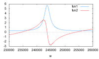
I've plotted the resistance seen by the input voltage as a function of its frequency below:

This diagram shows the real part of the resistance in blue and the imaginary part in red. The primary and secondary are tuned here to the same frequency. The secondary is loaded only lightly, i.e. the Q is about 100.
The operating points for a coil with zero current switching are the frequencies at which the imaginary part is zero, i.e. current and voltage are in phase. There are 3 of these points, the upper and the lower one corresponding to the poles and an additional middle one. I believe, the middle one is hard to use since it is unstable. Consider the case, where the input frequency is a bit too high. This will cause the current phase to shift to a bit earlier. The feedback will then respond with a higher frequency in order to catch up with the current. This will then lead to even more phase shift. So a runaway situation develops. The upper and the lower poles behave just the opposite and are stable.
The real part of the resistance is the sum of R1 and Rtr and shows us how much current we get in the primary and by the equation above, how high the secondary voltage is. For the highest secondary voltage, we should be at double the resistance of R1.
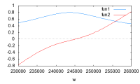
In the diagram below I'm showing a case with heavier streamer loading at a secondary Q of 10, i.e. a 10 times lower R2 as in the previous diagram. I am not sure whether this magnitude of loading is realistic, though.

Here there is just one operating frequency left. This happens, when k<1/Q. The real part of the resistance shows a much broader and lower peak. The maximum of the peak is R1+k^2*R2*L1/L2 and is located at the secondary frequency.
To a certain extent, this explains why the primary current rises up during ground arcs. The load resistance R2 goes to zero, which makes the resistance seen by the power supply go to its lowest value i.e. R1. Ground arcs are heavily dynamic events, though, and not really covered by this steady state model.
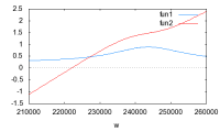
Usually the primary is tuned to a somewhat lower frequency than the secondary. That is shown in the diagram below:

The operating frequency, given by the zero crossing of the imaginary part, is now far in the tail of the real part of the resistance, i.e. the coil is very inefficient. When the input voltage is turned up, though, the capacitance caused by streamers will decrease the secondary resonance frequency, so the peak moves left, which increases the efficiency and reduces primary current. This can go too far, so that the primary current is reduced by a value of Rtr way above its optimal value of R1. It is easier to tune a coil, which has a low secondary Q, since the slopes of the peak are flatter.
Here's a small script for the wxMaxima program which I used to make the plots. It also shows the parameters of my coil.
f(w):=(1+%i*w*R1*C1-w^2*L1*C1)/(%i*w*C1)-% i*k^2*w^2*L1*L2*(%i/R2-w*C2)/(1+%i*w*L2/R2- w^2*L2*C2) $
wxplot2d([realpart(f(2*%pi*w)),imagpart(f(2*% pi*w))],[w,230000,260000]),k=0.08,R1=0.25,R2=3300000,C1=75e-9,C2=19.4e-12,L1=5.7e-6,L2=0.022;
Re: A bit of DRSSTC theory
Steve Conner, Tue Nov 22 2011, 05:53PM
Excellent post sir! I agree with all of the conclusions. I have seen the "middle" pole in lab experiments, attempted to lock a PLL to it, and failed. The results I got agree with your explanation of the instability. (It is really a zero, not a pole, as far as I know.)
In my DRSSTC design work I always assumed a loaded Q of 10, but I don't really have experimental results to back this up, except that my coil seemed to work and put out roughly the spark length I expected.
There is an alternative "hungry streamer" theory that says that the spark load finds an operating point according to the maximum power transfer theorem. But this is complicated by the fact that Tesla coil streamers are ballasted by their own capacitance to ground, not just the coil's output impedance. The capacitance is a function of streamer length, which in turn is a function of energy dumped into the streamers, so the whole thing gets iterative.
Steve Conner, Tue Nov 22 2011, 05:53PM
Excellent post sir!
 I agree with all of the conclusions. I have seen the "middle" pole in lab experiments, attempted to lock a PLL to it, and failed. The results I got agree with your explanation of the instability. (It is really a zero, not a pole, as far as I know.)
In my DRSSTC design work I always assumed a loaded Q of 10, but I don't really have experimental results to back this up, except that my coil seemed to work and put out roughly the spark length I expected.
There is an alternative "hungry streamer" theory that says that the spark load finds an operating point according to the maximum power transfer theorem. But this is complicated by the fact that Tesla coil streamers are ballasted by their own capacitance to ground, not just the coil's output impedance. The capacitance is a function of streamer length, which in turn is a function of energy dumped into the streamers, so the whole thing gets iterative.
Re: A bit of DRSSTC theory
Dr. Dark Current, Tue Nov 22 2011, 07:18PM
Thanks for the great info
Dr. Dark Current, Tue Nov 22 2011, 07:18PM
Thanks for the great info

Re: A bit of DRSSTC theory
Uspring, Wed Nov 23 2011, 01:13PM
Hi Steve,
nice to know that my paperwork concurs with your experience
I'm very interested in whether the heavy load condition, where the poles disappear, really occurs. Tuning is quite different as in the light load case. Under heavy loads you can tune the primary to any frequency below the real part resistance peak. In the light load case you are prevented from doing this by the frequency split between the poles. You can't, e.g. tune to the peak position itself, which would give you the lowest primary currents and the highest efficiency, although probably not the biggest sparks. Does anybody know?
I don't think that is really a different theory. Whenever there is enough power the the streamer will grow and thereby affect the the power output of the coil. That will then have effect on the streamer length. Like you described. Basically it depends on the timing, i.e. whether the coils output will change in the timescale that the streamer changes. That is before the interrupter shuts off.
Uspring, Wed Nov 23 2011, 01:13PM
Hi Steve,
nice to know that my paperwork concurs with your experience

In my DRSSTC design work I always assumed a loaded Q of 10, but I don't really have experimental results to back this up, except that my coil seemed to work and put out roughly the spark length I expected.
I'm very interested in whether the heavy load condition, where the poles disappear, really occurs. Tuning is quite different as in the light load case. Under heavy loads you can tune the primary to any frequency below the real part resistance peak. In the light load case you are prevented from doing this by the frequency split between the poles. You can't, e.g. tune to the peak position itself, which would give you the lowest primary currents and the highest efficiency, although probably not the biggest sparks. Does anybody know?
There is an alternative "hungry streamer" theory that says that the spark load finds an operating point according to the maximum power transfer theorem. But this is complicated by the fact that Tesla coil streamers are ballasted by their own capacitance to ground, not just the coil's output impedance. The capacitance is a function of streamer length, which in turn is a function of energy dumped into the streamers, so the whole thing gets iterative.
I don't think that is really a different theory. Whenever there is enough power the the streamer will grow and thereby affect the the power output of the coil. That will then have effect on the streamer length. Like you described. Basically it depends on the timing, i.e. whether the coils output will change in the timescale that the streamer changes. That is before the interrupter shuts off.
Print this page