
PSQCW DRSSTC
BSVi, Wed Jun 08 2011, 04:38PMI'm started my new project. Essentially, it's QCW DRSSTC, but instead of controlling bus voltage, i'm going to skip some pumping periods (that's what PS stands for).
What I have up to date is a part of future schematic, swcad model, and main part of cpld firmware.
Simulation demonstrates really good perfomance, so i'm going to build this in "metal". The resonator itself is 75mm diameter 150mm long pipe, winded with 0.18mm wire + small toroid. Resonant frequency is 377kHz. The primary will be high-impedance one - 30turns@3mm litz + 3.2nF cap.
Just wanted to open project thread :)
]svarog.pdf[/file]
Re: PSQCW DRSSTC
BSVi, Wed Jun 08 2011, 04:43PM
Sorry for double posting, but the the forum doesnt allow to upload rar's and jpeg's (yes, jpg are allowed, and jpeg's are not). And I for some reason can't add files to my previous post, so doubleposting.

]svarog_model.zip[/file]
BSVi, Wed Jun 08 2011, 04:43PM
Sorry for double posting, but the the forum doesnt allow to upload rar's and jpeg's (yes, jpg are allowed, and jpeg's are not). And I for some reason can't add files to my previous post, so doubleposting.

]svarog_model.zip[/file]
Re: PSQCW DRSSTC
Ash Small, Wed Jun 08 2011, 05:34PM
You can add files by posting them in the 'attachments' section, then using the 'edit' facility, and 'copy' and 'paste' to copy them into the original post.
It's a bit long winded, but it generally works in the end.
Ash Small, Wed Jun 08 2011, 05:34PM
You can add files by posting them in the 'attachments' section, then using the 'edit' facility, and 'copy' and 'paste' to copy them into the original post.
It's a bit long winded, but it generally works in the end.
Re: PSQCW DRSSTC
Goodchild, Wed Jun 08 2011, 07:53PM
Hmm interesting idea. Looking foreword to seeing more.
Goodchild, Wed Jun 08 2011, 07:53PM
Hmm interesting idea. Looking foreword to seeing more.
Re: PSQCW DRSSTC
Mathias, Wed Jun 15 2011, 07:23AM
The controller will set the allowed maximum current after the first trip ?
Steve Conner suggested , by feeding a ramped signal into the OCD comparator, that should simulate somewhat QCW-ish mode of operation.
Mathias, Wed Jun 15 2011, 07:23AM
The controller will set the allowed maximum current after the first trip ?
Steve Conner suggested , by feeding a ramped signal into the OCD comparator, that should simulate somewhat QCW-ish mode of operation.
Re: PSQCW DRSSTC
Goodchild, Thu Jun 16 2011, 09:00AM
You know I'm interested to see if that would have the same effect, because in my work whit the QCW the current don't really change or "ramp" much over the period of the burst. As seen here.
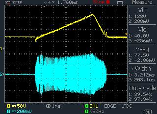
This is true for the primary circuit at least. As for the secondary current and voltage well that gets a bit more complex but, from what I have seen from Steve Ward the voltage of the spark itself also doesn't change or "ramp" much over the period of the burst. SO what changes as the spark gets bigger? Well the secondary current would be an indicator but I still need to do more thinking on this.
So in short what I'm tiring to say is that I don't think you would get the same effect by slowly adding cycles to the burst to control current. I think practically the way to do it would be with voltage control.
But we will see! Interested to see more. keep up the good work!
Eric
Goodchild, Thu Jun 16 2011, 09:00AM
Mathias wrote ...
The controller will set the allowed maximum current after the first trip ?
Steve Conner suggested , by feeding a ramped signal into the OCD comparator, that should simulate somewhat QCW-ish mode of operation.
The controller will set the allowed maximum current after the first trip ?
Steve Conner suggested , by feeding a ramped signal into the OCD comparator, that should simulate somewhat QCW-ish mode of operation.
You know I'm interested to see if that would have the same effect, because in my work whit the QCW the current don't really change or "ramp" much over the period of the burst. As seen here.

This is true for the primary circuit at least. As for the secondary current and voltage well that gets a bit more complex but, from what I have seen from Steve Ward the voltage of the spark itself also doesn't change or "ramp" much over the period of the burst. SO what changes as the spark gets bigger? Well the secondary current would be an indicator but I still need to do more thinking on this.
So in short what I'm tiring to say is that I don't think you would get the same effect by slowly adding cycles to the burst to control current. I think practically the way to do it would be with voltage control.
But we will see! Interested to see more. keep up the good work!

Eric
Re: PSQCW DRSSTC
BSVi, Thu Jun 16 2011, 10:07AM
>The controller will set the allowed maximum current after the first trip ?
The controller sets maximum allowed current all the time, regardless of trip count.
>in my work whit the QCW the current don't really change or "ramp" much over the period of the burst
Thank you for this information. I thought primary current is changing druing voltage ramp.
Anyway, I'll try my approach. If linear current ramp wouldnt work, I'll be able to reproduce your primary current shape to mimic conventional QCW.
Re: PSQCW DRSSTC
BSVi, Fri Jun 17 2011, 01:29PM
Finished layout for my prototype. The PCB is fairly complex, but i think i'll manage to manufacture it at home.

BSVi, Fri Jun 17 2011, 01:29PM
Finished layout for my prototype. The PCB is fairly complex, but i think i'll manage to manufacture it at home.

Re: PSQCW DRSSTC
101111, Sat Jun 18 2011, 07:49AM
This is great, always love to see something new here at 4hv!
101111, Sat Jun 18 2011, 07:49AM
This is great, always love to see something new here at 4hv!
Re: PSQCW DRSSTC
BSVi, Mon Jun 20 2011, 12:19PM
I have some progress since last post:
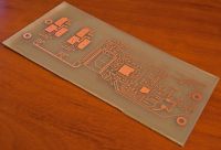
1. I have manufactured PCB, it turned out not as complicated as I thought it to be.
2. I wrote firmware to have something to get up and running quickly when parts arrives.
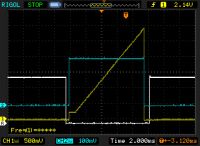
The blue trace is "interrupter". Tesla starts up at 0->1 transition and runs till 1->0 transition occurs. After that controller waits for zerocrossing and shuts down.
The yellow trace is desired secondary current. You can notice a little offset at te begining - it was introduced to allow tesla to start up.
The white trace is "nRESET" signal. This signal is required to reset interrupter logic if no zerocrossing occured after interrupter's 1->0 transition.


Re: PSQCW DRSSTC
Matt Edwards, Tue Jun 21 2011, 03:42PM
Beautiful board for home brew!
Matt Edwards, Tue Jun 21 2011, 03:42PM
Beautiful board for home brew!
Re: PSQCW DRSSTC
Patrick, Tue Jun 21 2011, 08:07PM
Did you do the UV photo thing? Came out nice.
Patrick, Tue Jun 21 2011, 08:07PM
Did you do the UV photo thing? Came out nice.
Re: PSQCW DRSSTC
BSVi, Wed Jun 22 2011, 04:52PM
>Did you do the UV photo thing?
Yep, I did exactly that.
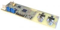
My parts arrived and I done with soldering. Now I have to make some cables and power source to be able to download firmware to micro and cpld.
Offtop: Tomorrow I'll get my Engeneer degree, so congrats to me ))
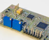
BSVi, Wed Jun 22 2011, 04:52PM
>Did you do the UV photo thing?
Yep, I did exactly that.
My parts arrived and I done with soldering. Now I have to make some cables and power source to be able to download firmware to micro and cpld.
Offtop: Tomorrow I'll get my Engeneer degree, so congrats to me ))


Re: PSQCW DRSSTC
Patrick, Wed Jun 22 2011, 05:41PM
HEY !!! Thats great !!!
For me it will be another 2 years at least, and that assumes they wont layoff anymore of my professors.
Patrick, Wed Jun 22 2011, 05:41PM
BSVi wrote ...
Offtop: Tomorrow I'll get my Engeneer degree, so congrats to me ))
Offtop: Tomorrow I'll get my Engeneer degree, so congrats to me ))
HEY !!! Thats great !!!
For me it will be another 2 years at least, and that assumes they wont layoff anymore of my professors.
Re: PSQCW DRSSTC
Steve Ward, Sat Jun 25 2011, 02:17AM
I was recently trying to simulate something much like this idea. The "issue" is that the QCW DRSSTC is fairly high coupling, and low energy storage (low Q) system, so in starting/stopping the drive voltage, the system energy ramps up and down faster than i think is useful for stable spark growth.
How did you manage to get such a smooth ramp? That is, what are the parameters for the Tesla coil (LCs and coupling) Im guessing perhaps low coupling and very high primary impedance? I wonder what happens when you put some losses on the secondary, if the system can supply the power to grow the sparks?
It is indeed a fun idea to be able to achieve all the modulation within the bridge itself. I also like that you are going for a CPLD, this is something i want to play with in the future.
Re: PSQCW DRSSTC
BSVi, Sat Jun 25 2011, 12:28PM
>HEY !!! Thats great !!!
Thanks )) Now, I'm officially an engeneer and can continue with tesla stuff.
I'v done cpld debugging, and now I have deadtime and interrupter workinkg well. I also had to introduce small amount of hysteresis (30mV) on feedback comparator to make it stable. Next step now is to test pulse skipper behavior, and to make power supply for IGBT drivers.
>The "issue" is that the QCW DRSSTC is fairly high coupling, and low energy storage (low Q)
That's bad news. I used pretty random model for simulation based only on desired geometry, without taking spark load into account, the parameters are:
Primary R: 1 Ohm
Primary L: 62.07µ
Primary C: 2865p
Secondary R: 100 Ohm
Secondary L: 19986µH
Secondary C: 8.9p
Coupling: 0.3
>I wonder what happens when you put some losses on the secondary, if the system can supply the power to grow the sparks?
Shurely, the system will be able to supply power (it's drsstc after all), but with lowering Q the current ripple increases. I'm not shure about implications of high current ripple, so that's another thing to find out.
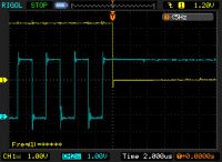
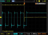
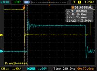


Re: PSQCW DRSSTC
Steve Ward, Sat Jun 25 2011, 03:52PM
Ok, i see, you just have a rather large primary surge impedance so that the evolution of primary current is already slow on its own, so that controls the "ramping up too fast" issue. But, i think if you put a loss in there (try putting an R across the secondary output of R = 3X Zsec, for starters) then i think you will see some new behavior (probably limited primary current, and it should drop faster when you skip cycles).
Ive been discussing this pulse skipping topology with Jimmy Hynes (coincidentally to seeing this project), and we both agreed that pulse skipping can produce "smoother" current/voltage control if 1) you lower primary secondary coupling, and 2) you lower secondary impedance so its effective Q is larger. You also need to tune the primary and switch it to operate at the primary zero, and not either of the pole frequencies (run an AC sweep of your DRSSTC, and look at how the primary phase crosses zero degrees 3 times, the center one is at a minimum of primary current, this is the "zero", the other 2 phase crossings happen at the "poles"). Whats going on in this case is that you have a series LC (primary leakage and tank cap) feeding a parallel resonant (secondary L and C) where both LCs are tuned to the same frequency. You essentially store reactive power in the parallel LC, and only feed *real* power from the inverter through the series LC. This makes the secondary look like a *stiff* voltage source, which you can then modulate with the pulse skipping. After studying this operation for the last few days, it remains interesting to me, but there are other challenges involved with making it work, i think. I have not yet done a design study to see how well it might work as coupling goes less than .1 and with really low secondary Z.
Anyway, will be looking forward to what you do with this setup. Im quite excited to see someone trying this method of control!
Re: PSQCW DRSSTC
BSVi, Mon Jul 04 2011, 08:58AM
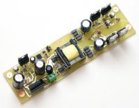
I'v done power suppy for my controller. It supplies 3.3v for controler itself and 2 isolated pairs of +11 and -4v for IGBT's gates.
>But, i think if you put a loss in there then i think you will see some new behavior (probably limited primary current, and it should drop faster when you skip cycles).
Yep, I tried to simulate system with load and saw exactly what you are talking about - the current drops significantly with added secondary load. The solution is obvious - to decrease coupling, but I dont know if it would have "QCW effect" with low coupling.
>you lower secondary impedance so its effective Q is larger.
I think, you mean to increase secondary impedance, but secondary impedance is not something that you can rely on. It varies greatly with steammer loading. So decreased coupling looks like a better solution to me.

Re: PSQCW DRSSTC
Arcstarter, Mon Jul 04 2011, 09:55PM
Well if you wind a secondary with litz, IE less impedance to high frequency, isn't it's Q higher? If so, that means less impedance means higher Q. Lower impedance means lower damping, and a high Q resonator would have less damping than a low Q one, as i understand it.
This is a cool project! If only i thought of it first

Re: PSQCW DRSSTC
GeordieBoy, Mon Jul 04 2011, 10:31PM
Hi BSVi,
Just a quick comment about that PSU...

I don't know if this is running directly off the mains supply? Or is being fed from some isolated low-voltage supply?
It looks like you've got a copper line marking out the border of the PCB (running right around the outside of the board.) This goes very close to both the primary side and secondary side circuits, and severely reduces the creepage and clearance distances! This undoes all of the good of having a large isolation distance between the input and output sides and that fancy tex-e or margin wound transformer.
I'd definitely scratch that off if my life depended on isolation!
-Richie,
GeordieBoy, Mon Jul 04 2011, 10:31PM
Hi BSVi,
Just a quick comment about that PSU...

I don't know if this is running directly off the mains supply? Or is being fed from some isolated low-voltage supply?
It looks like you've got a copper line marking out the border of the PCB (running right around the outside of the board.) This goes very close to both the primary side and secondary side circuits, and severely reduces the creepage and clearance distances! This undoes all of the good of having a large isolation distance between the input and output sides and that fancy tex-e or margin wound transformer.
I'd definitely scratch that off if my life depended on isolation!

-Richie,
Re: PSQCW DRSSTC
BSVi, Tue Jul 05 2011, 09:05AM
Arcstarter, Steve Ward
Sorry, I confused "secondary tank impedance" which is 1/Q with secondary impedance, which is jwL.
GeordieBoy
BTW, the capacitance between primary and secondary sides is as low as 12pf.
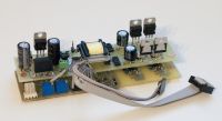
I have my controller board assembled now and it works well (at least, on test rig). I plan to make some power electronics this week, so stay tuned .
.
BSVi, Tue Jul 05 2011, 09:05AM
Arcstarter, Steve Ward
Sorry, I confused "secondary tank impedance" which is 1/Q with secondary impedance, which is jwL.
GeordieBoy
I don't know if this is running directly off the mains supply?It is fed from 220->12v linear transformer.
BTW, the capacitance between primary and secondary sides is as low as 12pf.
I'd definitely scratch that off if my life depended on isolation!You are right! Thank you for pointing that out.
I have my controller board assembled now and it works well (at least, on test rig). I plan to make some power electronics this week, so stay tuned
 .
.
Re: PSQCW DRSSTC
JimmyH, Sat Jul 09 2011, 07:57PM
DRSSTCs ain't magic you know! If you drive it at the primary resonance frequency, it'll suck power, but it will have to ring up very high before any power is transferred to the secondary, and the load will be very tuning (ie streamer length) dependent. Steve has been driving his QCW at the other (upper) pole for these reasons. At the upper pole, it'll only pull significant power through a high Z primary tank if the tuning is just right, which it can't be for all frequencies.
Decreasing coupling or detuning would fix it in theory, but there are practical reasons to not be running the primary at an effective Q of 1000. The "QCW" effect is dependent only on the voltage history of the topload (for a given geometry, at least). Everything else is screened off so the sparks "can't know".
Secondary impedance (the amount of topload voltage divided by the circulating current) becomes a lot more stable when its low. If you stick 100 secondaries/toploads in parallel, it'll be much less disturbed by the same spark. This is the same as lowering inductance and increasing capacitance.
There are two advantages of storing the energy in the secondary instead of the primary. The first is that it's easier to come up with a capacitor on the secondary side that can handle the current, the second is that you can always drive the upper pole without tuning issues.
Steve and I didn't settle on this idea because we weren't sure if it'd work with poor regulation, but it might. Just make sure whatever drive setup you choose can pump a half amp into realistically modeled streamers at 50kv before you start actually making the thing.
JimmyH, Sat Jul 09 2011, 07:57PM
Shurely, the system will be able to supply power (it's drsstc after all), but with lowering Q the current ripple increases. I'm not shure about implications of high current ripple, so that's another thing to find out.
DRSSTCs ain't magic you know! If you drive it at the primary resonance frequency, it'll suck power, but it will have to ring up very high before any power is transferred to the secondary, and the load will be very tuning (ie streamer length) dependent. Steve has been driving his QCW at the other (upper) pole for these reasons. At the upper pole, it'll only pull significant power through a high Z primary tank if the tuning is just right, which it can't be for all frequencies.
Yep, I tried to simulate system with load and saw exactly what you are talking about - the current drops significantly with added secondary load. The solution is obvious - to decrease coupling, but I dont know if it would have "QCW effect" with low coupling.
Decreasing coupling or detuning would fix it in theory, but there are practical reasons to not be running the primary at an effective Q of 1000. The "QCW" effect is dependent only on the voltage history of the topload (for a given geometry, at least). Everything else is screened off so the sparks "can't know".
I think, you mean to increase secondary impedance, but secondary impedance is not something that you can rely on. It varies greatly with steammer loading. So decreased coupling looks like a better solution to me.
Secondary impedance (the amount of topload voltage divided by the circulating current) becomes a lot more stable when its low. If you stick 100 secondaries/toploads in parallel, it'll be much less disturbed by the same spark. This is the same as lowering inductance and increasing capacitance.
There are two advantages of storing the energy in the secondary instead of the primary. The first is that it's easier to come up with a capacitor on the secondary side that can handle the current, the second is that you can always drive the upper pole without tuning issues.
Steve and I didn't settle on this idea because we weren't sure if it'd work with poor regulation, but it might. Just make sure whatever drive setup you choose can pump a half amp into realistically modeled streamers at 50kv before you start actually making the thing.
Re: PSQCW DRSSTC
BSVi, Mon Aug 29 2011, 06:00AM
Hi, I'm sorry for being absent for this long. Now I'm ready to return to my design.
Control electronics is ready and functional, but I'm in doubt about resonator design (I know, it's complicated thing). It's great if anybody is eager to help me.
Input data:
I have irg4pc40w transistors with 40amps of constant current rating.
Also, I have nice small toroid with 5pF capacitance
That's all :)
I tried to simulate resonator as shown in attachement. I'm unable to acheive half an amp into 300k load (is it reallistical model of streamer?)
As for now, my model pumping 150ma at 42kV into 300k load at 40amp of primary current. the model is also attached.

]resonator.zip[/file]
BSVi, Mon Aug 29 2011, 06:00AM
Hi, I'm sorry for being absent for this long. Now I'm ready to return to my design.
Control electronics is ready and functional, but I'm in doubt about resonator design (I know, it's complicated thing). It's great if anybody is eager to help me.
Input data:
I have irg4pc40w transistors with 40amps of constant current rating.
Also, I have nice small toroid with 5pF capacitance
That's all :)
I tried to simulate resonator as shown in attachement. I'm unable to acheive half an amp into 300k load (is it reallistical model of streamer?)
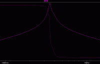
You also need to tune the primary and switch it to operate at the primary zeroHow can I do that? Both poles has higher gain, any self-resonating circuit will lock on any of them. Anyway, when I lowering coupling for the system to work, zero dissapears (look at my ac simulation in attachement). If I increase coupling, zero appears again, but streamer current decreses.
As for now, my model pumping 150ma at 42kV into 300k load at 40amp of primary current. the model is also attached.


]resonator.zip[/file]
Re: PSQCW DRSSTC
Mathias, Mon Aug 29 2011, 09:28AM
Not quite, atleast streamer/spark parameters have "time" dependant parts. It's series resistance should drop significantly (from 1Mohm to a few Kohm or an even lower value) if currents start to flow also it's series inductance rises a bit. (but this can be left out of consideration cause the change takes place on the order of a few hunder nH)
Mathias, Mon Aug 29 2011, 09:28AM
BSVi wrote ...
I tried to simulate resonator as shown in attachement. I'm unable to acheive half an amp into 300k load (is it reallistical model of streamer?)
I tried to simulate resonator as shown in attachement. I'm unable to acheive half an amp into 300k load (is it reallistical model of streamer?)
Not quite, atleast streamer/spark parameters have "time" dependant parts. It's series resistance should drop significantly (from 1Mohm to a few Kohm or an even lower value) if currents start to flow also it's series inductance rises a bit. (but this can be left out of consideration cause the change takes place on the order of a few hunder nH)
Re: PSQCW DRSSTC
Steve Ward, Wed Aug 31 2011, 06:01AM
For my streamer load model i used something like 2pF per foot of spark length in series with something in the range of 20-50k ohms. With this sort of loading i was able to match my real world measurements for all voltages and currents.
For the resonator, i think since the top voltage is probably going to be low, it cant hurt to go with a short, wide coil form (4.5" PVC would be my choice on a coil this size).
As to the pole/zero issue. Yes, the poles have more gain, but it seemed possible to either use a PLL, or just a VCO, to start the system off at the Fzero frequency. With no streamer load the primary current will be tiny and very distorted, so this is where the VCO would have to just power through and keep switching at some specified frequency. After the streamer starts to pull more energy from the secondary, the inverter current should increase and start looking more sinusoidal. At some point along here it seemed feasible to start using primary current feedback to maintain good ZCS, and the system should keep oscillating at this frequency as the pole frequencies should not really be present after so many cycles. Admittedly, this is not a real simple approach, and i dont think anyone knows yet whether or not it will work all that well. Id probably stick with the pole operation for now if you want to get it up and running quickly.
Re: PSQCW DRSSTC
BSVi, Wed Aug 31 2011, 03:26PM
Hi! Thank you for your answers. I'v done quite a lot of simulations today.
I dont want to bother with tuning to zero - it's too complicated and requires me to remake my control board, so I'll tune my coil to pole.
Its not obvoious to me which pole to use. Common logic tells me that it's better to tune to lower pole - when spark grows, it detunes secondary lower, so both coils stays tuned. But simulation shows that secondary influences primary and as spark grows primary goes lower. From secondary/primary current ratio it's better to tune to the upper pole. When transition from upper to lower pole tuning occurs, overal gain expirienses dip at zero's frequency - that's (from my point of view) another drawback of tuning to the upper pole.
I can't also came up with coupling. The coupling doest influences anything much and that surprises me. Now I use 0.2 coupling.
Now my settings are (with 22mH/10.35p secondary):
Secondary is, as you suggested, 4.5''*9'' crowned with my 5pf toroid . Coupling is 0.2.
For higher pole I use: 5n MMC, 50uH primary: 676mA into streammer / 85amps of primary current
For lower pole I use: 5n MMC, 70uH primary: 596mA into streammer / 48amps of primary current
Lower pole variant has higher impedance, so I also will be able to control current more smoothly.
I'm a newbie in resonator design, so forgive me if all i'm saying is a one huge mistake
Attached is my current resonator design. I use two 2p/35k networks to switch betwen 0/1/2ft sparks by cutting wires :)

BSVi, Wed Aug 31 2011, 03:26PM
Hi! Thank you for your answers. I'v done quite a lot of simulations today.
I dont want to bother with tuning to zero - it's too complicated and requires me to remake my control board, so I'll tune my coil to pole.
Its not obvoious to me which pole to use. Common logic tells me that it's better to tune to lower pole - when spark grows, it detunes secondary lower, so both coils stays tuned. But simulation shows that secondary influences primary and as spark grows primary goes lower. From secondary/primary current ratio it's better to tune to the upper pole. When transition from upper to lower pole tuning occurs, overal gain expirienses dip at zero's frequency - that's (from my point of view) another drawback of tuning to the upper pole.
I can't also came up with coupling. The coupling doest influences anything much and that surprises me. Now I use 0.2 coupling.
Now my settings are (with 22mH/10.35p secondary):
Secondary is, as you suggested, 4.5''*9'' crowned with my 5pf toroid
 . Coupling is 0.2.
For higher pole I use: 5n MMC, 50uH primary: 676mA into streammer / 85amps of primary current
For lower pole I use: 5n MMC, 70uH primary: 596mA into streammer / 48amps of primary current
Lower pole variant has higher impedance, so I also will be able to control current more smoothly.
I'm a newbie in resonator design, so forgive me if all i'm saying is a one huge mistake

Attached is my current resonator design. I use two 2p/35k networks to switch betwen 0/1/2ft sparks by cutting wires :)

Re: PSQCW DRSSTC
Goodchild, Wed Aug 31 2011, 05:44PM
I think Steve has his QCW tuned the same way I do, but I found that the best performance was at the upper pole.
I also like the upper pole because I can drive at the magic >350KHz and don't have to make a supper small secondary with very little windings. A helping part of this is the higher coupling, as this drives the 2 poles farther apart making it possible to have even a high drive freq without making a small secondary. This is the main reason I like the upper pole.
Eric
Re: PSQCW DRSSTC
BSVi, Wed Aug 31 2011, 07:55PM
Goodchild, the bad thing is that PS QCW differs from plain QCW - it can't have such a high coupling.
>magic >350KHz
What's magic in >350kHz? I tought that increasing frequency is the mean to make coil smaller so it doesn't occuply half of living room.
BSVi, Wed Aug 31 2011, 07:55PM
Goodchild, the bad thing is that PS QCW differs from plain QCW - it can't have such a high coupling.
>magic >350KHz
What's magic in >350kHz? I tought that increasing frequency is the mean to make coil smaller so it doesn't occuply half of living room.
Re: PSQCW DRSSTC
Goodchild, Wed Aug 31 2011, 10:59PM
I'm not so sure that I entirely agree with what Steve said about the system having to be low coupling in order for it to have low current ripple. It should be a high Q system but from the research I have done I have a slightly different opinion on it. I am in the process of building a very similar driver for my QCW that uses large IGBT and a similar control setup to yours to control current.
Although it's any one's guess at this point how the system will react in the "real world" all we have to go on at the moment is simulations. My simulations suggest that even with a high coupling and losses you can still achieve reasonable current ripple if you keep the impedance and Q high.
yes >350KHz seems to be the magic freq to drive the resonator at. Any lower and you will begin to experience branching of the sparks. This has been shown on the QCW and also with many VTTC as well. The higher you go in frequency the straighter the sparks seem to get.
Goodchild, Wed Aug 31 2011, 10:59PM
BSVi wrote ...
Goodchild, the bad thing is that PS QCW differs from plain QCW - it can't have such a high coupling.
>magic >350KHz
What's magic in >350kHz? I tought that increasing frequency is the mean to make coil smaller so it doesn't occuply half of living room.
Goodchild, the bad thing is that PS QCW differs from plain QCW - it can't have such a high coupling.
>magic >350KHz
What's magic in >350kHz? I tought that increasing frequency is the mean to make coil smaller so it doesn't occuply half of living room.
I'm not so sure that I entirely agree with what Steve said about the system having to be low coupling in order for it to have low current ripple. It should be a high Q system but from the research I have done I have a slightly different opinion on it. I am in the process of building a very similar driver for my QCW that uses large IGBT and a similar control setup to yours to control current.
Although it's any one's guess at this point how the system will react in the "real world" all we have to go on at the moment is simulations. My simulations suggest that even with a high coupling and losses you can still achieve reasonable current ripple if you keep the impedance and Q high.
yes >350KHz seems to be the magic freq to drive the resonator at. Any lower and you will begin to experience branching of the sparks. This has been shown on the QCW and also with many VTTC as well. The higher you go in frequency the straighter the sparks seem to get.
Re: PSQCW DRSSTC
BSVi, Thu Sept 01 2011, 02:15PM
Now I want you to take a look at my resonator design and tell - is it a good starting point? I just do not want to make it in vain.
So here are specs:
BSVi, Thu Sept 01 2011, 02:15PM
I'm not so sure that I entirely agree with what Steve said about the system having to be low couplingI think Steve is right - the secondary has high loss this loss is transfered to primary by coupling. The less coupling the less loss in primary - the less loss the higher Q, the higher Q the smoother current control.
I am in the process of building a very similar driver for my QCW that uses large IGBT and a similar control setup to yours to control currentIf you need any schematics, models, pcbs or firmwares from my project to shorten your developement, just tell :)
with a high coupling and losses you can still achieve reasonable current ripple if you keep the impedance and Q high.You cant have high losses and keep Q high - that mutually exclusive things.
Now I want you to take a look at my resonator design and tell - is it a good starting point? I just do not want to make it in vain.
So here are specs:
Secondary is, 4.5''*9'' crowned with my 5pf toroid . Coupling is 0.2.
For higher pole: 5n MMC, 50uH primary: 676mA into streammer / 85amps of primary current
For lower pole: 5n MMC, 70uH primary: 596mA into streammer / 48amps of primary current
Re: PSQCW DRSSTC
Goodchild, Fri Sept 02 2011, 06:07AM
What size wire are you going to use for the 4.5 x 9? I also use a 4.5 x 9 as well and it's wound with 30 AWG wire. Now the thing is that because my coupling is high ~0.4k my upper pole for this secondary is at about 380KHz. If the coupling was lower then this secondary would probably be kinda useless because the upper pole would drop down below 350KHz and as I said that is not good for strait sparks.
I'm hoping that my current ripple will be ok for my already built secondary. If it comes down to having to resort to lower coupling I will end up making a new secondary with a higher F0.
Thanks for offering to share your data, I'm at about the same point you are right now as far as production. I also took a slightly different path as far as control. I didn't want a uC so instead I used dedicated logic. We will have to compare data from our two systems when we finished them both.
Are you going to use a half or full bridge for you design?
Re: PSQCW DRSSTC
BSVi, Fri Sept 02 2011, 06:34AM
Tell me about your primary resonator - what are your L and C values and what's the reason why you chosen that values?
BSVi, Fri Sept 02 2011, 06:34AM
What size wire are you going to use for the 4.5 x 9?Oddly, but I was going for 30AWG too (or 0.26mm diameter, since we have everyting metric in ukraine)
Are you going to use a half or full bridge for you design?I'm going to use half-bridge to half the amount of fried transistors. Power transistors are quite expensive here. Eventually, if I'll have everyting working, and like the result I'll upgrade to full bridge. Whar are you going to use?
Tell me about your primary resonator - what are your L and C values and what's the reason why you chosen that values?
Re: PSQCW DRSSTC
Goodchild, Fri Sept 02 2011, 06:52PM
I plan to use a full bridge as I have the parts on hand. My primary capacitor with be 15nF making my primary about 11.69uH for 380KHz operation. I wanted a high impedance tank but I also had to work with the parts I had. I happen to have a supper awesome 15nF MICA (thanks to DR Spark) and it is just the right capacitance for my design so it's what I plan to use.
A lot of my part decisions are based on what I have on hand.
Half bridge also makes the control logic a lot easy! With a full bridge you have to have some complex logic in order for your system to keep oscillating while you are skipping cycles. A half bridge will do this naturally because one side of the bridge will pass AC. Although I'm would like to use dedicated logic it's getting to the point were it's just to complex and it would be worth while to use a uC.
May I ask what uC you are using and what clock you plan to run it at? I figured that the clock needs to be at least 4x as fast as the resonant frequency.
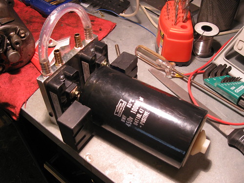
Here is the bridge that I'm constructing for my coil

Re: PSQCW DRSSTC
BSVi, Fri Sept 02 2011, 07:38PM
BSVi, Fri Sept 02 2011, 07:38PM
My primary capacitor with be 15nFThat's three times larger than what I'm going for. My capacitance is limited by IGBTs current, so no wonder you have larger cap.
for 380KHz operationI'm not really shure those bricks you using could be pushed to such a high frequency.
May I ask what uC you are using and what clock you plan to run it at?I'm using stm32f100c6 for ramp generation (it has DAC), and epm3032 for managing high frequency stuff. The CPLD runs asynchronously so there is no "clock" frequency.
Here is the bridge that I'm constructing for my coilOmg! My irg4pc40w half-bridge look really feeble compared to this monster!
Re: PSQCW DRSSTC
Goodchild, Fri Sept 02 2011, 11:04PM
Hehe every one thinks I can't run those IGBTs at 380KHz not even sure I believe it yet, but I have a special trick that allows me to run them that high; all though this will be the first time I test it. I started with 60N60s and they ran ok at 380KHz but it will be a feat if I manage to these suckers running at that frequency.
This bridge should be able to process at least 300A+ of current at QCW duty.
ahhh your using like an FPGA well not the same but similar. Man those things are annoying to program but awesome!
Re: PSQCW DRSSTC
Goodchild, Mon Sept 26 2011, 11:39PM
Sorry to double post but I have some new information to add.
Ive been doing a great deal of simulation with this type of modulation and I tried two variants. I tried just the comparator (like your design BSVi) and also I tried a delta sigma modulation stage.
Now the regular comparator was dismal in performance. I had very high current ripple throughout the burst and was almost completely unusable. It had a very large 5KHz ripple.
The delta sigma modulator did better, but despite it's awesome name it too has horrible current ripple at least at the beginning of the burst where current needs to be low.
Here is the delta sigma modulator.
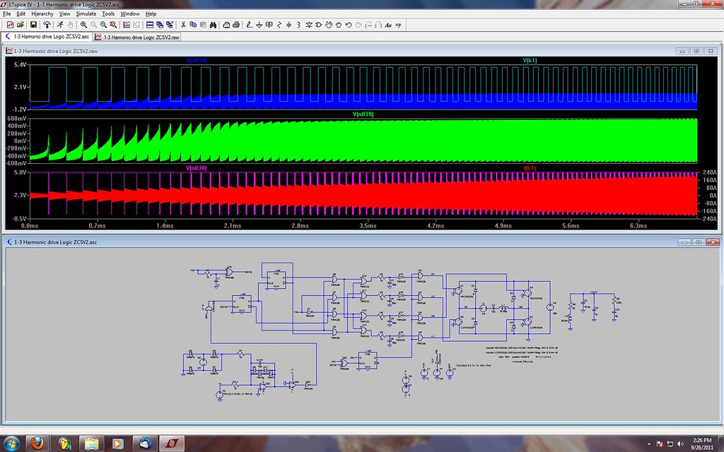
The primary current is in red and you can see it has some nasty ripple, the ripple increases in frequency and decreases in amplitudes as the burst prolongs as would be expected from a modulator of this type. The regular comparator modulator had the same ripple throughout the duration of the burst.
I tried these simulation with a variety of couplings and tank impedance and the results turn out more or less the same.
Just some fruit for thought! I hope your hardware version is coming along as well? I'm curios to see if this changes with a real system. Although I have a hard time believing it will work in real life if it doesn't work that well in simulation.
Eric
Goodchild, Mon Sept 26 2011, 11:39PM
Sorry to double post but I have some new information to add.
Ive been doing a great deal of simulation with this type of modulation and I tried two variants. I tried just the comparator (like your design BSVi) and also I tried a delta sigma modulation stage.
Now the regular comparator was dismal in performance. I had very high current ripple throughout the burst and was almost completely unusable. It had a very large 5KHz ripple.
The delta sigma modulator did better, but despite it's awesome name it too has horrible current ripple at least at the beginning of the burst where current needs to be low.
Here is the delta sigma modulator.

The primary current is in red and you can see it has some nasty ripple, the ripple increases in frequency and decreases in amplitudes as the burst prolongs as would be expected from a modulator of this type. The regular comparator modulator had the same ripple throughout the duration of the burst.
I tried these simulation with a variety of couplings and tank impedance and the results turn out more or less the same.
Just some fruit for thought! I hope your hardware version is coming along as well? I'm curios to see if this changes with a real system. Although I have a hard time believing it will work in real life if it doesn't work that well in simulation.
Eric
Print this page