
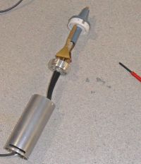
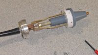
Internals of a Tek P6013A HV O-scope probe.
Patrick, Wed Feb 02 2011, 05:29AMok i start with pics.
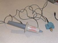
The total device (As bougt from Ebay).
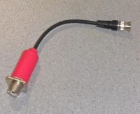
Radio Shack UHF to BNC changer.
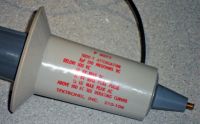
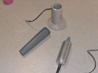

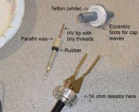
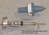

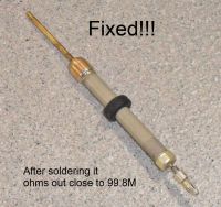
Re: Internals of a Tek P6013A HV O-scope probe.
Steve Maurer, Fri Feb 04 2011, 04:25PM
Thank you for sharing these pictures with us.
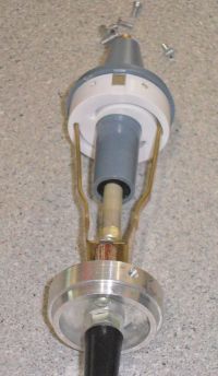
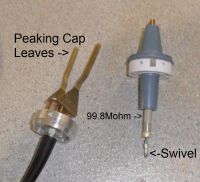
I find the leaf capacitor arrangement interesting.
- Steve
Steve Maurer, Fri Feb 04 2011, 04:25PM
Thank you for sharing these pictures with us.
I find the leaf capacitor arrangement interesting.
- Steve
Re: Internals of a Tek P6013A HV O-scope probe.
Pinky's Brain, Fri Feb 04 2011, 04:45PM
I assume it's there to couple the high frequency components to the output? Because without it the grounded shield pulls the output signal to ground?
Pinky's Brain, Fri Feb 04 2011, 04:45PM
I assume it's there to couple the high frequency components to the output? Because without it the grounded shield pulls the output signal to ground?
Re: Internals of a Tek P6013A HV O-scope probe.
Patrick, Fri Feb 04 2011, 06:08PM
Patrick, Fri Feb 04 2011, 06:08PM
Pinky's Brain wrote ...
I assume it's there to couple the high frequency components to the output? Because without it the grounded shield pulls the output signal to ground?
This statement eludes me, please clarify.I assume it's there to couple the high frequency components to the output? Because without it the grounded shield pulls the output signal to ground?
Re: Internals of a Tek P6013A HV O-scope probe.
Pinky's Brain, Sat Feb 05 2011, 12:58AM
Well the grounded shielding has a large parasitic capacitance to the resistor, if that was all there was to the probe then for higher frequencies most of the signal gets coupled to the shielding long before it gets to the low voltage arm of the divider (the electric field along the resistor is no longer symmetrical like it is for instance with your resistor from the other threads with the hoops). I assume the leaf capacitor is not grounded, but connects to the low voltage arm ... so I assume it's there to couple the high frequency components to the low voltage arm to counteract the effect from the shielding ...
Re: Internals of a Tek P6013A HV O-scope probe.
Patrick, Sat Feb 05 2011, 04:44AM

the coax cable, the length from the probe can end, torwards the comp-box spans 10Ft and the center strand has 225K resistrence. therefore 225K/10ft = 22.5kohms per foot.

Patrick, Sat Feb 05 2011, 04:44AM
Pinky's Brain wrote ...
Well the grounded shielding has a large parasitic capacitance to the resistor, if that was all there was to the probe then for higher frequencies most of the signal gets coupled to the shielding long before it gets to the low voltage arm of the divider (the electric field along the resistor is no longer symmetrical like it is for instance with your resistor from the other threads with the hoops). I assume the leaf capacitor is not grounded, but connects to the low voltage arm ... so I assume it's there to couple the high frequency components to the low voltage arm to counteract the effect from the shielding ...
Do you mean the 1k (R111) hold up resistor...at HF the 1k (Common Cartbon Comp, 1/2 W) can get much hotter then the HV resistor! charging 3pf and discharging at 75Mhz and 200v must make a lot of heat.Well the grounded shielding has a large parasitic capacitance to the resistor, if that was all there was to the probe then for higher frequencies most of the signal gets coupled to the shielding long before it gets to the low voltage arm of the divider (the electric field along the resistor is no longer symmetrical like it is for instance with your resistor from the other threads with the hoops). I assume the leaf capacitor is not grounded, but connects to the low voltage arm ... so I assume it's there to couple the high frequency components to the low voltage arm to counteract the effect from the shielding ...

the coax cable, the length from the probe can end, torwards the comp-box spans 10Ft and the center strand has 225K resistrence. therefore 225K/10ft = 22.5kohms per foot.


Re: Internals of a Tek P6013A HV O-scope probe.
Pinky's Brain, Sat Feb 05 2011, 02:49PM
To me it seems that a handheld probe is significantly harder to design than a standalone probe connected through a low induction copper strap. With a stand alone probe you can keep the electric field across the HV resistor uniform (like your capacitive hoops in the other thread) which simplifies modelling it's operation.
The moment you put a grounded metal shield around it which goes close to the tip the behaviour of the system becomes much harder to predict.
Pinky's Brain, Sat Feb 05 2011, 02:49PM
Patrick wrote ...
Do you mean the 1k (R111) hold up resistor
With low voltage arm? I mean the 1K resistor and everything to the right of it in the schematic.Do you mean the 1k (R111) hold up resistor
To me it seems that a handheld probe is significantly harder to design than a standalone probe connected through a low induction copper strap. With a stand alone probe you can keep the electric field across the HV resistor uniform (like your capacitive hoops in the other thread) which simplifies modelling it's operation.
The moment you put a grounded metal shield around it which goes close to the tip the behaviour of the system becomes much harder to predict.
Re: Internals of a Tek P6013A HV O-scope probe.
Patrick, Sat Feb 05 2011, 07:42PM
Patrick, Sat Feb 05 2011, 07:42PM
Pinky's Brain wrote ...
The moment you put a grounded metal shield around it which goes close to the tip the behaviour of the system becomes much harder to predict.
Yes I worry about this. The NorthStar's dont even have sheilding running up torwards the tip at all , just that blue nylon.The moment you put a grounded metal shield around it which goes close to the tip the behaviour of the system becomes much harder to predict.
Re: Internals of a Tek P6013A HV O-scope probe.
Patrick, Mon Feb 07 2011, 05:37AM
I believe the Tek P6013, P6014, P6015 all have that metal shield so they can treat the whole path as a lossy-transmission line?
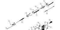
What about this...
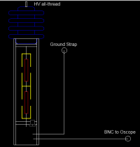
Yellow are copper "Park-like" Caps, Red are resistors. The bottom most section are where compensation and LV componets live.
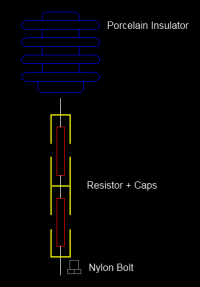
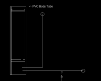
Patrick, Mon Feb 07 2011, 05:37AM
Pinky's Brain wrote ...
To me it seems that a handheld probe is significantly harder to design than a standalone probe connected through a low induction copper strap. With a stand alone probe you can keep the electric field across the HV resistor uniform (like your capacitive hoops in the other thread) which simplifies modelling it's operation.
The moment you put a grounded metal shield around it which goes close to the tip the behaviour of the system becomes much harder to predict.
The NorthStar's do have a large topand bottom ring, to equalize the field and as you said I guess thats where some capacity comes from too.To me it seems that a handheld probe is significantly harder to design than a standalone probe connected through a low induction copper strap. With a stand alone probe you can keep the electric field across the HV resistor uniform (like your capacitive hoops in the other thread) which simplifies modelling it's operation.
The moment you put a grounded metal shield around it which goes close to the tip the behaviour of the system becomes much harder to predict.
I believe the Tek P6013, P6014, P6015 all have that metal shield so they can treat the whole path as a lossy-transmission line?
What about this...

Yellow are copper "Park-like" Caps, Red are resistors. The bottom most section are where compensation and LV componets live.


Re: Internals of a Tek P6013A HV O-scope probe.
Patrick, Sat Oct 01 2011, 11:51PM
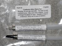
Ok ive got my silver epoxy so ill make the attempt to fix this probe tonight.
Silver epoxy
Patrick, Sat Oct 01 2011, 11:51PM
Ok ive got my silver epoxy so ill make the attempt to fix this probe tonight.
Silver epoxy

Re: Internals of a Tek P6013A HV O-scope probe.
Patrick, Mon Oct 03 2011, 10:29PM
Ive come to the conclusion i may not be able to fix this probe. But I have still learned alot so it was worth the 60 USD and teh time lost trying to fix it.
First, the capacitence (3pf) at 60 hz was enough to damp the 10kV sine signal to just 28 mV! through a 99.8 Mohm resistor. And though the compensation box is hard to fix, when my body's stray capacitence was attached to the LV node, the O-scope showed a perfect 17V sine wave. so capacittance does play an enormous role in how these devices work.
I continue the my building of my own probes.
Print this page