
Reverse-engineering a small XRT
klugesmith, Sun Nov 21 2010, 06:20PMThis is to report some electrical measurements on a dental x-ray transformer (nominally 70 kVp, 7 mA, 60 Hz). They give some perspective to low-duty-cycle imperatives.
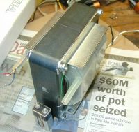
My transformer has a 5.25-inch square laminated E-E core, in two riveted sections.
I had to take it apart to rework the mounting brackets.
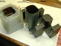
Took the opportunity to set aside the plastic-shrouded secondary coils. Made some electrical measurements with no load, and no high voltage in the way.
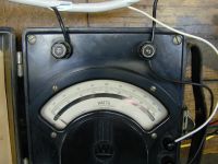
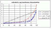
At 120 V RMS, the core is nearly saturated - I figure 1.82 T peak flux. As in a MOT, this is to get plenty of volts per turn per pound. Magnetizing current reaches about 6 amps RMS. A real wattmeter indicated that about 86 W were heating the transformer: 36 W copper loss in the 1.0 ohm primary winding, and 50 W core loss.
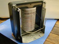
To get the flux, I made an inordinately fancy sense winding with 17 turns and the best flux linkage I could manage. Voltage ratio shows that the primary has exactly 174 turns, in 2 layers: from the white lead it's right hand helix up, then left hand helix back down to the black lead. We get 0.690 V RMS per turn from 2.2 in^2 (14.2 cm^2) core area.
Here is a chart of the data. Magnetizing current was measured two ways: first with an old Amprobe clip-on analog meter, then with a true-RMS Fluke DMM in series. The difference at lower voltages could be due to the clip-on meter reading low, or to a bigger core air gap when I assembled it for the series measurements. (minimizing the airgap is uncritical at such high flux levels).
For next time: secondary winding details and estimates of losses with a HV load.
Re: Reverse-engineering a small XRT
Patrick, Mon Nov 22 2010, 06:19AM
this is a great thread.... please continue to post.
Patrick, Mon Nov 22 2010, 06:19AM
this is a great thread.... please continue to post.
Re: Reverse-engineering a small XRT
Xray, Fri Nov 26 2010, 06:47PM
Nice job testing the magnetic properties of the core!
I repair and rebuild dental X-ray heads for a living, and this is one brand that I have repaired MANY times over the years. It's a Gendex GX-770. I can tell you that a good working head will draw about 7 or 8 Amps from the mains. The control circuit has an "inverse voltage protection circuit" in series with the primary winding which consists of a high current diode across a low ohms (typically 10 Ohms) resistor. During the half cylcle when the tube is conducting and loading the hv secondary, the diode is forward biased, and as a result, shorts out the 10 Ohm resistor, which allows the transformer to get full voltage. During the half cycle when the tube is not conducting, the diode is reversed bias, and the voltage then flows through the resistor which limits the high voltage to a safe value so that it doesn't arc between windings. The diode/resistor circuit is only needed for X-ray applications. You won't need it if you use the transformer for a jacob's ladder or Tesla coil.
Also keep in mind that X-ray transformers, unlike neon sign transformers, are not current limited. Therefore, as the secondary load current increases, the primary current will continue to increase until either the transformer burns out, or the mains fuse blows.
Have fun!
Xray
Re: Reverse-engineering a small XRT
klugesmith, Sat Dec 18 2010, 06:19AM
Here's some more data.
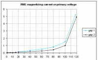
1) Reassembled the core w/ attention to minimizing the airgap. This cut the magnetizing current in half, except near saturation where the iron permeability is relatively low.
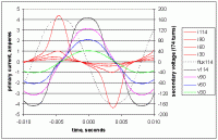
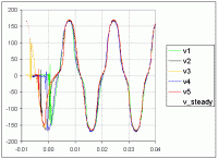
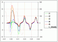
2) captured primary current and secondary voltage waveforms, still unloaded, for RMS primary voltages of 30, 60, 90, and 114. That's as high as I could get with the isolation transformer on hand. Near saturation, it takes a large current to create the required magnetization (so the induced back-EMF almost matches the applied voltage). When the current peaks, IR drop subtracts significantly from the effective primary voltage. This distorts the secondary voltage waveform, but happens near zero crossing so we don't lose much RMS voltage. Dotted line indicates core flux for the 114V case, inferred by integrating the voltage of secondary winding.
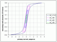
We can plot BH curves, with current on one axis and integrated voltage on the other. This could be observed in real time using a voltage integrator circuit (fluxmeter) and an oscilloscope with X/Y mode. By factoring in the core dimensions and number of winding turns, the X axis could be labeled in oersteds or amps/meter, and the Y axis in teslas or gauss.
Finally, I took the opportunity to get some inrush current measurements when the transformer is turned on by a switch at arbitrary phase of mains voltage cycle. Purpose is to illustrate that we drop right into steady-state magnetizing current if the switch is closed at voltage PEAK. We get the highest inrush current when switch is closed at voltage zero crossing. It would be much higher still if we had a full 120 V RMS and no isolation transformer.
klugesmith, Sat Dec 18 2010, 06:19AM
Here's some more data.
1) Reassembled the core w/ attention to minimizing the airgap. This cut the magnetizing current in half, except near saturation where the iron permeability is relatively low.

2) captured primary current and secondary voltage waveforms, still unloaded, for RMS primary voltages of 30, 60, 90, and 114. That's as high as I could get with the isolation transformer on hand. Near saturation, it takes a large current to create the required magnetization (so the induced back-EMF almost matches the applied voltage). When the current peaks, IR drop subtracts significantly from the effective primary voltage. This distorts the secondary voltage waveform, but happens near zero crossing so we don't lose much RMS voltage. Dotted line indicates core flux for the 114V case, inferred by integrating the voltage of secondary winding.

We can plot BH curves, with current on one axis and integrated voltage on the other. This could be observed in real time using a voltage integrator circuit (fluxmeter) and an oscilloscope with X/Y mode. By factoring in the core dimensions and number of winding turns, the X axis could be labeled in oersteds or amps/meter, and the Y axis in teslas or gauss.

Finally, I took the opportunity to get some inrush current measurements when the transformer is turned on by a switch at arbitrary phase of mains voltage cycle. Purpose is to illustrate that we drop right into steady-state magnetizing current if the switch is closed at voltage PEAK. We get the highest inrush current when switch is closed at voltage zero crossing. It would be much higher still if we had a full 120 V RMS and no isolation transformer.


Re: Reverse-engineering a small XRT
Meatball, Sat Dec 18 2010, 06:31AM
What are you going to do with this transformer?
EDIT: That's a lot of POT!
Meatball, Sat Dec 18 2010, 06:31AM
What are you going to do with this transformer?
EDIT: That's a lot of POT!
Re: Reverse-engineering a small XRT
Sulaiman, Sat Dec 18 2010, 12:50PM
I like the resistor//diode in the primary trick - new one to me.
I would expect a transformer to interleave the core laminations to absolutely minimise any effective airgap for minimum magnetising current, and have the primary and secondary co-axial.
Why does this x-ray transformer separate the primary and secondary windings with an airgap? A leakage flux path has been deliberately introduced....just curious.
Re: Reverse-engineering a small XRT
GeordieBoy, Sat Dec 18 2010, 02:33PM
Some good testing of the transformer.
> Reassembled the core w/ attention to minimizing the airgap. This cut the magnetizing current in half, except near saturation where the iron permeability is relatively low.
I was going to say that the no-load current draw (or "magnetising current") will be quite dependent on how well you can get the faces of the two core halves to mate. Even the smallest of air-gap in here will increase the no-load current draw of the transformer by decreasing it's inductance. That is why most lower voltage power transformers use interleaved E and I laminations. It makes the core set virtually impossible to disassemble once its been dipped though.
The 3rd harmonic distortion you are seeing in the voltage and current waveforms is a clear sign that the core is operating well past the onset of saturation.
For transformers the minimum "inrush current" is always observed when the power is turned on at a voltage peak. This is because the transformer flux is the integral of the applied voltage. If you turn on at a voltage zero crossing, then the peak flux integrates up to twice the normal peak value and the core is pushed into saturation. In a design where the core is already barely big enough, this can cause huge current spikes if turned on at a voltage zero. This transient core flux imbalance gradually decays away after switch on depending on the DC resistance of the winding and the supply impedance. For large high power transformers they can continue to growl and draw big inrush spikes for several cycles because the DC resistance is so low.
-Richie,
Re: Reverse-engineering a small XRT
Proud Mary, Sat Dec 18 2010, 03:04PM
How about a soft starter to temper the existential threat of sudden on-ness - all those violent spikes and roaring surges searching for short cuts in every weakness.
Proud Mary, Sat Dec 18 2010, 03:04PM
How about a soft starter to temper the existential threat of sudden on-ness - all those violent spikes and roaring surges searching for short cuts in every weakness.
Re: Reverse-engineering a small XRT
Xray, Sat Dec 18 2010, 06:15PM
Dental X-ray manufacturer's have been using that trick for many decades. I suspect (and I'm only guessing here) that the transformer needs to be designed in such a way that it can accept a "modified" sinewave. By that I mean, half of the sinewave has a lower peak voltage than the other half, and, because of the diode, the waveform doesn't look "normal".
I think the air gap is there to allow the oil to help cool the windings, and it also provides insulation between the hv secondaries, and the primary. Most 60Hz AC X-ray transformers for dental application utilize two secondary windings with each "low" end tied to ground, or one of them is sometimes used to monitor the tube current, and is brought out to a terminal (the GX-770 does this). In a 70KV tubehead, each secondary provides 35KV -- one for the cathode of the tube, and one for the anode. This design allows for smaller spacing inside the head because there is only 35KV at any one point to ground. Only the X-ray tube "sees" 70KV. That's another "trick" that is utilized in dental tubeheads.
Of course, in "DC" heads, things are quite different. The Cathode is at ground potential, and the anode get the full DC high voltage, usually from a CW multiplier.
Xray, Sat Dec 18 2010, 06:15PM
Sulaiman wrote ...
I like the resistor//diode in the primary trick - new one to me.
I like the resistor//diode in the primary trick - new one to me.
Dental X-ray manufacturer's have been using that trick for many decades. I suspect (and I'm only guessing here) that the transformer needs to be designed in such a way that it can accept a "modified" sinewave. By that I mean, half of the sinewave has a lower peak voltage than the other half, and, because of the diode, the waveform doesn't look "normal".
Sulaiman wrote ...
Why does this x-ray transformer separate the primary and secondary windings with an airgap? A leakage flux path has been deliberately introduced....just curious.
Why does this x-ray transformer separate the primary and secondary windings with an airgap? A leakage flux path has been deliberately introduced....just curious.
I think the air gap is there to allow the oil to help cool the windings, and it also provides insulation between the hv secondaries, and the primary. Most 60Hz AC X-ray transformers for dental application utilize two secondary windings with each "low" end tied to ground, or one of them is sometimes used to monitor the tube current, and is brought out to a terminal (the GX-770 does this). In a 70KV tubehead, each secondary provides 35KV -- one for the cathode of the tube, and one for the anode. This design allows for smaller spacing inside the head because there is only 35KV at any one point to ground. Only the X-ray tube "sees" 70KV. That's another "trick" that is utilized in dental tubeheads.
Of course, in "DC" heads, things are quite different. The Cathode is at ground potential, and the anode get the full DC high voltage, usually from a CW multiplier.
Re: Reverse-engineering a small XRT
klugesmith, Sat Dec 18 2010, 07:24PM
Xray: thanks for the detail about typical current draw from the mains. You taught me the resistor||diode trick last year, after selling me the transformer. I haven't applied it yet, but you will see the waveforms when I do.
Here is another view of its function. In normal operation with self-rectifying Coolidge tube, the secondary winding carries a net DC current of 7 mA. That's about 487 ampere-turns.
Turns ratio is about 1:400, so to keep the core flux balanced we need an average DC current of 2.8 amps in the primary winding. I expect this will be in the form of 5.6 amp pulses during half of each cycle, in phase with the voltage, and will be superimposed on the magnetizing current as reported above.
Flyback converters also have net DC current in both primary in secondary, but the pulses are not concurrent, so each cycle's energy must be stored in the magnetic field, hence the airgap.
In the XRT case I think there's no deliberate airgap. The laminated core is non-interleaved to facilitate construction and service. A thin air gap in part of the contact area (due to non flatness) doesn't matter much because the flux density is so high -- the air is no longer 10000 times more reluctive than the iron. Look at the black and blue curves in my before-and-after chart.
Re: Reverse-engineering a small XRT
Andre, Tue Oct 16 2012, 12:04AM
I will like to see more pictures on the secondary of this transfomer, this is porn for engineers :)
how did you found the saturation point of this transfomer?
Andre, Tue Oct 16 2012, 12:04AM
I will like to see more pictures on the secondary of this transfomer, this is porn for engineers :)
how did you found the saturation point of this transfomer?
Re: Reverse-engineering a small XRT
Tony Matt, Tue Oct 23 2012, 04:52PM
Hi Xray !
I also like the "inverse voltage protection circuit" , or any device to treak the remanent magnetic flux.
Can you post the Gendex GX-770 circuit schematic ??
thanks
Tony
Tony Matt, Tue Oct 23 2012, 04:52PM
Hi Xray !
I also like the "inverse voltage protection circuit" , or any device to treak the remanent magnetic flux.
Can you post the Gendex GX-770 circuit schematic ??
thanks
Tony
Re: Reverse-engineering a small XRT
Xray, Tue Oct 23 2012, 08:27PM
If you are looking for the schematic diagram of the entire machine including the control circuits, I do not have that in digital form. You may be able to get a copy from Gendex for the asking if you tell them you are a dental equipment repair technician. The schematic diagram of the tubehead is very simple. Basically it's a transformer with 110VAC primary winding, and two 35KV secondary windings. There is also a low-voltage winding for the filament. The filament winding floats at 35KV above ground, and is wound on the same hv secondary that connects to the cathode of the X-ray tube. There is also a resistor that connects between the filament winding and the cathode hv winding. That resistor provides a bias for the grid of the tube.
Hope this helps.
Xray, Tue Oct 23 2012, 08:27PM
Tony Matt wrote ...
Hi Xray !
I also like the "inverse voltage protection circuit" , or any device to treak the remanent magnetic flux.
Can you post the Gendex GX-770 circuit schematic ??
thanks
Tony
Hi Xray !
I also like the "inverse voltage protection circuit" , or any device to treak the remanent magnetic flux.
Can you post the Gendex GX-770 circuit schematic ??
thanks
Tony
If you are looking for the schematic diagram of the entire machine including the control circuits, I do not have that in digital form. You may be able to get a copy from Gendex for the asking if you tell them you are a dental equipment repair technician. The schematic diagram of the tubehead is very simple. Basically it's a transformer with 110VAC primary winding, and two 35KV secondary windings. There is also a low-voltage winding for the filament. The filament winding floats at 35KV above ground, and is wound on the same hv secondary that connects to the cathode of the X-ray tube. There is also a resistor that connects between the filament winding and the cathode hv winding. That resistor provides a bias for the grid of the tube.
Hope this helps.
Re: Reverse-engineering a small XRT
Tony Matt, Wed Oct 24 2012, 03:10AM
Xray;
Thanks.
Tony
Tony Matt, Wed Oct 24 2012, 03:10AM
Xray;
Thanks.
Tony
Re: Reverse-engineering a small XRT
Tony Matt, Wed Oct 24 2012, 03:24AM
Hi Klugesmith.
I have understand that there is a airgap between two E cores.
Is the airgap an insulating material as cardboard, fiber presboard ? let me know the thickness.
Is the airgap in the central leg of the E core ? or it is distributed in the 3 legs of thre core?
Let me know how you did to minimizing the airgap.
thanks
Re: Reverse-engineering a small XRT
Andre, Wed Oct 24 2012, 04:26AM
So is the x-ray tube being power by AC voltage, no rectifier diodes?
Andre, Wed Oct 24 2012, 04:26AM
So is the x-ray tube being power by AC voltage, no rectifier diodes?
Re: Reverse-engineering a small XRT
Xray, Wed Oct 24 2012, 04:46PM
Yes, the tube operates in "self-rectification" mode. The anode and cathode are connected directly across the hv windings of the transformer, and it conducts every half-cycle of the sinewave when the anode is positive. In countries that have 60Hz mains like the U.S., the tube produces 60 pulses of X-rays during each second of exposure time. In the U.K. it produces 50 pulses per second.
Xray, Wed Oct 24 2012, 04:46PM
Andre wrote ...
So is the x-ray tube being power by AC voltage, no rectifier diodes?
So is the x-ray tube being power by AC voltage, no rectifier diodes?
Yes, the tube operates in "self-rectification" mode. The anode and cathode are connected directly across the hv windings of the transformer, and it conducts every half-cycle of the sinewave when the anode is positive. In countries that have 60Hz mains like the U.S., the tube produces 60 pulses of X-rays during each second of exposure time. In the U.K. it produces 50 pulses per second.
Re: Reverse-engineering a small XRT
Xray, Wed Oct 24 2012, 04:54PM
Tony - There is no air gap between the two sets of E cores. The ends are butted together and tightly clamped with the brackets and bolts. There is spacing between the primary and secondary windings, which is there to prevent arcing between the windings since the primary winding is essentially at ground potential, and the secondaries are sitting at 35KV each above ground. The insulation material is mostly some form of "fish paper", in combination with the oil that fills the entire tube head housing.
Xray, Wed Oct 24 2012, 04:54PM
Tony Matt wrote ...
Hi Klugesmith.
I have understand that there is a airgap between two E cores.
Is the airgap an insulating material as cardboard, fiber presboard ? let me know the thickness.
Is the airgap in the central leg of the E core ? or it is distributed in the 3 legs of thre core?
Let me know how you did to minimizing the airgap.
thanks
Tony - There is no air gap between the two sets of E cores. The ends are butted together and tightly clamped with the brackets and bolts. There is spacing between the primary and secondary windings, which is there to prevent arcing between the windings since the primary winding is essentially at ground potential, and the secondaries are sitting at 35KV each above ground. The insulation material is mostly some form of "fish paper", in combination with the oil that fills the entire tube head housing.
Re: Reverse-engineering a small XRT
Andre, Fri Oct 26 2012, 08:24PM
xray, so the secondary has some kind of fish paper between each layer? do you know how many layer it has?
Andre, Fri Oct 26 2012, 08:24PM
Xray wrote ...
Tony - There is no air gap between the two sets of E cores. The ends are butted together and tightly clamped with the brackets and bolts. There is spacing between the primary and secondary windings, which is there to prevent arcing between the windings since the primary winding is essentially at ground potential, and the secondaries are sitting at 35KV each above ground. The insulation material is mostly some form of "fish paper", in combination with the oil that fills the entire tube head housing.
Tony - There is no air gap between the two sets of E cores. The ends are butted together and tightly clamped with the brackets and bolts. There is spacing between the primary and secondary windings, which is there to prevent arcing between the windings since the primary winding is essentially at ground potential, and the secondaries are sitting at 35KV each above ground. The insulation material is mostly some form of "fish paper", in combination with the oil that fills the entire tube head housing.
xray, so the secondary has some kind of fish paper between each layer? do you know how many layer it has?
Re: Reverse-engineering a small XRT
Xray, Fri Oct 26 2012, 09:48PM
Nope... never bothered to count them. Why is that important to you?
Xray, Fri Oct 26 2012, 09:48PM
Andre wrote ...
xray, so the secondary has some kind of fish paper between each layer? do you know how many layer it has?
xray, so the secondary has some kind of fish paper between each layer? do you know how many layer it has?
Nope... never bothered to count them. Why is that important to you?
Re: Reverse-engineering a small XRT
Andre, Fri Oct 26 2012, 09:58PM
I was wondering how much voltage is going across each layer, and if it had anything in between each layer to prevent arcing
Andre, Fri Oct 26 2012, 09:58PM
Xray wrote ...
Nope... never bothered to count them. Why is that important to you?
Andre wrote ...
xray, so the secondary has some kind of fish paper between each layer? do you know how many layer it has?
xray, so the secondary has some kind of fish paper between each layer? do you know how many layer it has?
Nope... never bothered to count them. Why is that important to you?
I was wondering how much voltage is going across each layer, and if it had anything in between each layer to prevent arcing
Re: Reverse-engineering a small XRT
Xray, Sat Oct 27 2012, 12:15AM
Maybe Klugesmith could answer those questions since he recently took one apart.
Xray, Sat Oct 27 2012, 12:15AM
Andre wrote ...
I was wondering how much voltage is going across each layer, and if it had anything in between each layer to prevent arcing
I was wondering how much voltage is going across each layer, and if it had anything in between each layer to prevent arcing
Maybe Klugesmith could answer those questions since he recently took one apart.
Re: Reverse-engineering a small XRT
klugesmith, Sat Oct 27 2012, 01:44AM
Thank you for fielding* some questions addressed to me, x-ray.
I regret to report that this project has been on the back burner for almost two years.
The secondary coils have never been disassembled beyond the state in picture 2, nor did I ever plan to do so. That's how they stand today, in a plastic bag to reduce the infiltration of dust and moisture.
No promises now. To reverse-engineer the secondary configuration, I would first determine the wire gauge from the measurable DC resistance, turns count, and average turn length. Then seek combinations of turns per layer and number of layers, to match the coil dimensions and have reasonable values for axial and radial pitch.
The recent discussion inspires me to move ahead, and put to use some dielectric oil generously given to me by a 4hv reader in the next county. My vacuum pot (to permanently enclose the transformer, under dried and degassed oil) and pump have long been ready. Still need to choose a design for HV and LV wires passing through the 12-mm-thick acrylic lid. Feedthroughs must be vacuum-tight, with enough wire slack (or spring contacts) that the lid can be installed after transformer is bolted in place. Maybe the LV feedthroughs will penetrate the tank's side instead of its lid. In the meantime, I came to own a complete X-ray head and its control box, which obviates the first application of this transformer.
*Some readers might not recognize that term from the game of baseball, in which the San Francisco Giants may soon win the World Series. Do cricketers also field balls?
Re: Reverse-engineering a small XRT
Steve Conner, Sat Oct 27 2012, 08:21AM
Yes, cricketers do "field" things. Why does baseball have a World Series that's only a national competition?
Steve Conner, Sat Oct 27 2012, 08:21AM
Yes, cricketers do "field" things. Why does baseball have a World Series that's only a national competition?

Print this page