If you need assistance, please send an email to forum at 4hv dot org. To ensure your email is not marked as spam, please include the phrase "4hv help" in the subject line. You can also find assistance via IRC, at irc.shadowworld.net, room #hvcomm.
Support 4hv.org!
Donate:
4hv.org is hosted on a dedicated server. Unfortunately, this server costs and we rely on the help of site members to keep 4hv.org running. Please consider donating. We will place your name on the thanks list and you'll be helping to keep 4hv.org alive and free for everyone. Members whose names appear in red bold have donated recently. Green bold denotes those who have recently donated to keep the server carbon neutral.
Special Thanks To:
Aaron Holmes
Aaron Wheeler
Adam Horden
Alan Scrimgeour
Andre
Andrew Haynes
Anonymous000
asabase
Austin Weil
barney
Barry
Bert Hickman
Bill Kukowski
Blitzorn
Brandon Paradelas
Bruce Bowling
BubeeMike
Byong Park
Cesiumsponge
Chris F.
Chris Hooper
Corey Worthington
Derek Woodroffe
Dalus
Dan Strother
Daniel Davis
Daniel Uhrenholt
datasheetarchive
Dave Billington
Dave Marshall
David F.
Dennis Rogers
drelectrix
Dr. John Gudenas
Dr. Spark
E.TexasTesla
eastvoltresearch
Eirik Taylor
Erik Dyakov
Erlend^SE
Finn Hammer
Firebug24k
GalliumMan
Gary Peterson
George Slade
GhostNull
Gordon Mcknight
Graham Armitage
Grant
GreySoul
Henry H
IamSmooth
In memory of Leo Powning
Jacob Cash
James Howells
James Pawson
Jeff Greenfield
Jeff Thomas
Jesse Frost
Jim Mitchell
jlr134
Joe Mastroianni
John Forcina
John Oberg
John Willcutt
Jon Newcomb
klugesmith
Leslie Wright
Lutz Hoffman
Mads Barnkob
Martin King
Mats Karlsson
Matt Gibson
Matthew Guidry
mbd
Michael D'Angelo
Mikkel
mileswaldron
mister_rf
Neil Foster
Nick de Smith
Nick Soroka
nicklenorp
Nik
Norman Stanley
Patrick Coleman
Paul Brodie
Paul Jordan
Paul Montgomery
Ped
Peter Krogen
Peter Terren
PhilGood
Richard Feldman
Robert Bush
Royce Bailey
Scott Fusare
Scott Newman
smiffy
Stella
Steven Busic
Steve Conner
Steve Jones
Steve Ward
Sulaiman
Thomas Coyle
Thomas A. Wallace
Thomas W
Timo
Torch
Ulf Jonsson
vasil
Vaxian
vladi mazzilli
wastehl
Weston
William Kim
William N.
William Stehl
Wesley Venis
The aforementioned have contributed financially to the continuing triumph of 4hv.org. They are deserving of my most heartfelt thanks.
Registered Member #2861
Joined: Sun May 16 2010, 08:34PM
Location: Bavaria
Posts: 10
Hi I'm planning a DRSSTC and have some questions to it. But first the specifications:
secoundary-coil - diameter: 11 cm (4.3 in) - wire-diameter: 0,3 mm - height: 45 cm (17.7 in) - torus: 11 cm * 45 cm (4.3 in * 17.7 in) - number of windings: ~ 1500 - resonant frequency: 129.59 kHz
primary-coil - diameter: 24 cm (9.4 in) - space between windings: 1,2 cm (0.47 in) - wire-diameter: 6 mm (0.24 in) (-> copper-tube) - number of windings: 6
MMC One string consists of 6 MKP-10-1600 330n; 4 therefrom parallel gives altogether 220nF / 9,6 kVDC.
halfbridge consists of a FUJI 2MBI300U4H-120 (1200V, 800Apk). power supply: ~650VDC (system voltage + voltage doubler)
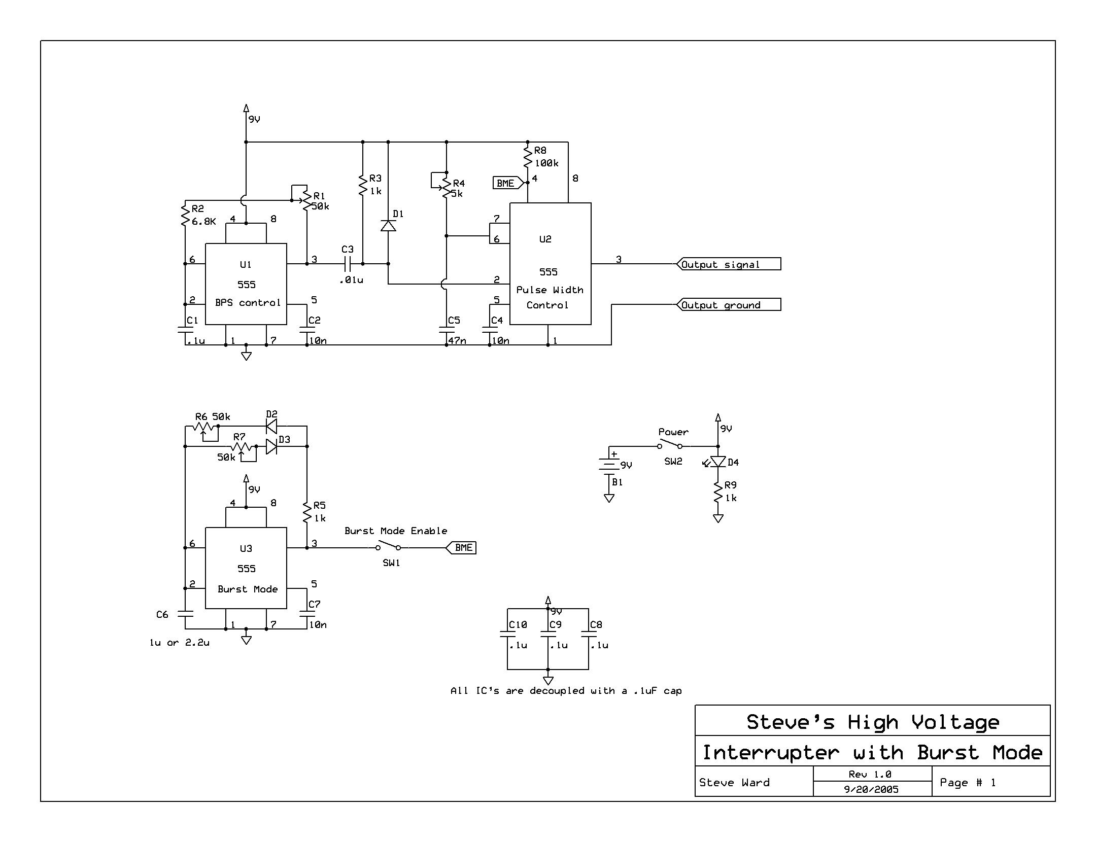
electronics - Steve Wards "New DRSSTC Driver" - interrupter: this one (without Burst Mode) - when the coil runs really good: CTC's musical interrupter
Now for the questions.. 1. How much current does the driver need?? 2. How big will be the power consumption approximately? Has anyone a DRSSTC with comparably specifications, so he could tell me how much power his coil needs? 3. In what way should I protect the grid against the DRSSTC (line filter, isolating transformer, fuses and so on)? Such things aren't really cheap if they have to transmit [insert answer of question 2 here] watt. 4. Is there anything you would not do like me? Please tell me.
so far.. greetings, skawesome
PS: My brother plotted the coil with HiCAD. But there are not 1660 windings on the secoundary because the computer wasn't able to handle with it.
Registered Member #30
Joined: Fri Feb 03 2006, 10:52AM
Location: Glasgow, Scotland
Posts: 6706
Power consumption is under your control, it depends on how you set the burst length and repetition rate of the interrupter.
For a coil this size, I'd plan for a couple of kilowatts.
As for line current: That depends on the power. Budget for a power factor of about 0.6, so the line current will be (power/voltage)*(1/0.6)
Your power output will probably be limited by how much current you can get out of the standard wall outlet in your country. (10A? 16A?) If you live in one of these countries that also has 400V three phase service, you might want to consider using that.
Protection: At least use a fuse or circuit breaker. Some basic RF filtering is also nice, this can be as simple as a capacitor from DC bus negative to ground.
Registered Member #1535
Joined: Wed Jun 11 2008, 11:37PM
Location: Northeastern Pennsylvania - USA
Posts: 117
I've been breaking open a few bricks of the Fuji series. One for example is a 2MBI300S-120
It appears to have a current limiting circuit in there similar to the Powerex RTC circuit in some of their bricks.
There's no mention of this in the Fuji datasheet. Powerex datasheets do mention it when they have it. I have no clue if this applies to your Fuji series bricks, but I thought it might be worthy to note...
Registered Member #1225
Joined: Sat Jan 12 2008, 01:24AM
Location: Beaumont, Texas, USA
Posts: 2253
TheBoozer wrote ...
I've been breaking open a few bricks of the Fuji series. One for example is a 2MBI300S-120
It appears to have a current limiting circuit in there similar to the Powerex RTC circuit in some of their bricks.
There's no mention of this in the Fuji datasheet. Powerex datasheets do mention it when they have it. I have no clue if this applies to your Fuji series bricks, but I thought it might be worthy to note...
Rich
I cracked open one of those Fuji 1.2kv 150amp (200 amps in the datasheet) bricks. I am now curious, what does this circuit look like, for fuuture reference? I'd imagine it involves a shunt resistor and some circuitry that disables the igbt by grounding the gate?
Registered Member #1535
Joined: Wed Jun 11 2008, 11:37PM
Location: Northeastern Pennsylvania - USA
Posts: 117
It looks like one little additional circuit with three leads. One lead attaches to the gate and two leads go to different spots on the IGBT. The two leads form a current mirror. Just like a shunt. I'm told people have had success snipping the two shunt leads on CM300 series Powerex modules.
Here's a photo I took a recently. It was only for size comparison. I could get a better closeup if requested. You can see in the very upper left, under the letter M of 2MBI the little die with two leads going to the IGBT below it.
Registered Member #2861
Joined: Sun May 16 2010, 08:34PM
Location: Bavaria
Posts: 10
News: My brother and I made the primary attachment and the torus.
(sry, I have made no photo of the torus yet)
At first I wanted to use a variac to control the voltage of the DRSSTC. But variacs that are able to transmit the power i want, are quite expensive. So a friend of mine suggested to use a dimmer. I think i need a trailing edge dimmer, because of the capacitive load of the voltage doubler. Could this work?
Registered Member #2292
Joined: Fri Aug 14 2009, 05:33PM
Location: The Wild West AKA Arizona
Posts: 795
skawesome wrote ...
At first I wanted to use a variac to control the voltage of the DRSSTC. But variacs that are able to transmit the power i want, are quite expensive. So a friend of mine suggested to use a dimmer. I think i need a trailing edge dimmer, because of the capacitive load of the voltage doubler. Could this work?
skawesome
Sorry but you can't use a SCR like circuit with a doubler, you need to input AC to the doubler in order for it to double the voltage.
Registered Member #480
Joined: Thu Jul 06 2006, 07:08PM
Location: North America
Posts: 644
skawesome -
What type of conductor are you planning to use for your primary coil, what is its outside diameter, and what is the diameter of the holes in your primary support?
You may find that threading the primary conductor through 35 holes simultaneously can be a real challenge; that's why almost everyone uses "notches" that allow the conductor to be "snapped in" radially, vs threaded through all the holes.
Registered Member #30
Joined: Fri Feb 03 2006, 10:52AM
Location: Glasgow, Scotland
Posts: 6706
Goodchild wrote ...
Sorry but you can't use a SCR like circuit with a doubler, you need to input AC to the doubler in order for it to double the voltage.
Yeah you can! Just replace the two diodes in the doubler with SCRs. It worked for me.
Or you can use diodes in the doubler and insert a triac in series with the AC input, it amounts to the same thing.
I've built two SSTCs with the DC bus voltage controlled by SCRs in this way.
Cheap lamp dimmers won't work, because the rectifier load is so non-linear. A professional dimmer rated for reactive loads might work, but I built my own phase angle controllers with hard firing.
Registered Member #2861
Joined: Sun May 16 2010, 08:34PM
Location: Bavaria
Posts: 10
Herr Zapp wrote ...
skawesome -
What type of conductor are you planning to use for your primary coil, what is its outside diameter, and what is the diameter of the holes in your primary support?
You may find that threading the primary conductor through 35 holes simultaneously can be a real challenge; that's why almost everyone uses "notches" that allow the conductor to be "snapped in" radially, vs threaded through all the holes.
Regards, Herr zapp
I'm planning to use a 6mm copper tube. The diameter is 24cm and the holes are made with a 6,1mm drill. I know, it will be not easy to get the tube into the attachment. My plan is to bend the tube to a coil and then "screw" it into the attachment. Maybe i will need some greace and a lot of patience. ;)
@Steve McConnor: Okay. It's good to know, that someone allready did something like this. :) I found found an IC (TCA 785) that could make this thing much easier for me. My idea was to rectify the 230VAC and use a MOSFET, because I can use SCRs only for leading-edge dimming. I will post a schematic diagram soon.
edit: here is the very simple dimmer schematic. just that you dont get the "rectify-thing" wrong.
This site is powered by e107, which is released under the GNU GPL License. All work on this site, except where otherwise noted, is licensed under a Creative Commons Attribution-ShareAlike 2.5 License. By submitting any information to this site, you agree that anything submitted will be so licensed. Please read our Disclaimer and Policies page for information on your rights and responsibilities regarding this site.


 Planning my first DRSSTC


