If you need assistance, please send an email to forum at 4hv dot org. To ensure your email is not marked as spam, please include the phrase "4hv help" in the subject line. You can also find assistance via IRC, at irc.shadowworld.net, room #hvcomm.
Support 4hv.org!
Donate:
4hv.org is hosted on a dedicated server. Unfortunately, this server costs and we rely on the help of site members to keep 4hv.org running. Please consider donating. We will place your name on the thanks list and you'll be helping to keep 4hv.org alive and free for everyone. Members whose names appear in red bold have donated recently. Green bold denotes those who have recently donated to keep the server carbon neutral.
Special Thanks To:
Aaron Holmes
Aaron Wheeler
Adam Horden
Alan Scrimgeour
Andre
Andrew Haynes
Anonymous000
asabase
Austin Weil
barney
Barry
Bert Hickman
Bill Kukowski
Blitzorn
Brandon Paradelas
Bruce Bowling
BubeeMike
Byong Park
Cesiumsponge
Chris F.
Chris Hooper
Corey Worthington
Derek Woodroffe
Dalus
Dan Strother
Daniel Davis
Daniel Uhrenholt
datasheetarchive
Dave Billington
Dave Marshall
David F.
Dennis Rogers
drelectrix
Dr. John Gudenas
Dr. Spark
E.TexasTesla
eastvoltresearch
Eirik Taylor
Erik Dyakov
Erlend^SE
Finn Hammer
Firebug24k
GalliumMan
Gary Peterson
George Slade
GhostNull
Gordon Mcknight
Graham Armitage
Grant
GreySoul
Henry H
IamSmooth
In memory of Leo Powning
Jacob Cash
James Howells
James Pawson
Jeff Greenfield
Jeff Thomas
Jesse Frost
Jim Mitchell
jlr134
Joe Mastroianni
John Forcina
John Oberg
John Willcutt
Jon Newcomb
klugesmith
Leslie Wright
Lutz Hoffman
Mads Barnkob
Martin King
Mats Karlsson
Matt Gibson
Matthew Guidry
mbd
Michael D'Angelo
Mikkel
mileswaldron
mister_rf
Neil Foster
Nick de Smith
Nick Soroka
nicklenorp
Nik
Norman Stanley
Patrick Coleman
Paul Brodie
Paul Jordan
Paul Montgomery
Ped
Peter Krogen
Peter Terren
PhilGood
Richard Feldman
Robert Bush
Royce Bailey
Scott Fusare
Scott Newman
smiffy
Stella
Steven Busic
Steve Conner
Steve Jones
Steve Ward
Sulaiman
Thomas Coyle
Thomas A. Wallace
Thomas W
Timo
Torch
Ulf Jonsson
vasil
Vaxian
vladi mazzilli
wastehl
Weston
William Kim
William N.
William Stehl
Wesley Venis
The aforementioned have contributed financially to the continuing triumph of 4hv.org. They are deserving of my most heartfelt thanks.
Registered Member #1643
Joined: Mon Aug 18 2008, 06:10PM
Location:
Posts: 1039
Maybe I'm just doing something wrong that I'm not even noticing. To start, I'm upgrading my SSTC (Steves SSTC MINI) from a halfbridge to a fullbridge. Right now, on the gate drive board I have a 10uF capacitor on one side of the GDT primary. The mosfets have a 2.5ohm resistor on them. The GDT consist of 6 primary turns, and 4X 12 turn secondary. I have 15V zeners on the 4 mosfets, which are rated 500V 50A (roughly a 500W max power peak) hiperfet.
So the problem is the GDT. I'm just bearly able to get any output from my SSTC at 30V (maybe 2mm) and I wasnt sure if maybe it was the waveform.
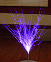
In this picture, You can see green blips on top and bottom. These are just about exactly 15V. The squiggly line, I have no idea why that is there. The more capacitance I added to the Primary of the GDT, the lower it dropped. I already have 10uF, so I figured something is just...wrong.
If you need a larger image, Right click, copy link, and past. For any pictures below!
Here I have the coil turned on, You can see it's at least getting feedback from my coil.
Here the coil is on again, I turned the Volts / Div up, and this is the ~350khz waveform of the coil
Does anyone have any tips for me on solving this problem? Spent maybe a week trying different capacitance..resistance..I changed up the GDT multiple times...Also, Is there a schematic that shows how to properly hook up the CT for feedback. I just have one connection of the CT to ground, The other connection goes to a resistor, then the 74HC14N. Some reason I recall you need a resistor and capacitor...But I wasn't sure, so I don't have one!! Bridge design PCB board layout 60mm X 60mm board
Registered Member #91
Joined: Thu Feb 09 2006, 03:03PM
Location: The Netherlands
Posts: 45
I would first try to get a good looking gate drive waveform before trying anything else or powering up the coil. That is, just apply a square wave of the right frequency to the inputs of your gate drivers and start working from there.
Are you sure you are measuring correctly? Try measuring the gate drive waveform with your scope set to DC and not AC.
What kind of coupling capacitor are you using? 10 uF sounds pretty large to me, I've had good results using a 1 uF MKP X-2 capacitor (the X-2 rating is probably overkill, but I guess at least some kind of MKP pulse capacitor is recommended).
Also, you should be able to drive the MOSFETs using a GDT with a 1:1 ratio, as they only need >10 V to turn on.
It's a matter of debugging, really. Start measuring at the beginning (which would be the inputs of your gate drivers in this case) and if the signal gets messed up modify the offending part until everything looks good from start to finish. When you've got decent gate waveforms, you can start working on the feedback and all that.
Registered Member #15
Joined: Thu Feb 02 2006, 01:11PM
Location:
Posts: 3068
I agree. Work on the gate waveform before doing anything else. Keep the MOSFETs connected to the GDT, but don't apply power to them and work on cleaning up your gate.
Registered Member #51
Joined: Thu Feb 09 2006, 04:17AM
Location:
Posts: 263
Perhaps one of your fets is shorted G-S? What frequency is your coil running at? 6 turns sounds a bit low for the goldmine cores I use atleast. I needed about 10 turns to get nice square waveforms at 300khz. Is the first picture your gate drive waveform? I would remove all but one FET from the output of your gate drive transformer, feed your driver a signal near the resonant frequency of your coil and take a look at the gate waveform again.
Registered Member #1643
Joined: Mon Aug 18 2008, 06:10PM
Location:
Posts: 1039
Will do. I know when I scoped the waveform coming out of the driver board TO the primary of the GDT, I had good waveforms. I'll change the 6 turns to 12 turns so its a 1:1 ratio.
As started earlier, The capacitors on the primary of the GDT is a 10uF. I'll stick it down to 1uF. Each gate has a 2.5ohm resistor (and I have a 10ohm mounted so I can switch easily). The capacitors on the bridge is a 400V 0.68uF (0.007ohm ESR) capacitor and 600V 6uF capacitor. I figured since my design is very compact, I wouldn't need 10uF. However, I do have 10uF worth of caps.
I'll post waveform pictures later tonight on what I get. Thanks!
Registered Member #152
Joined: Sun Feb 12 2006, 03:36PM
Location: Czech Rep.
Posts: 3384
If the mini SSTC is not getting feedback, one of the gate driver just goes HIGH the other LOW on the interrupter pulse, and the GDT primary then "rings down" with the series capacitance, that's the damped waveform you see and its normal with no feedback to the antenna.
Registered Member #15
Joined: Thu Feb 02 2006, 01:11PM
Location:
Posts: 3068
Also, those caps are WAAAYYYY overkill for the given application. With a simple SSTC, you can live with small board mounted electrolytics - no need for monster cans. Might save you some room. In fact, you really don't need the caps at all. Just feed half-rectified AC into the bridge. You won't really see much of a difference.
Registered Member #51
Joined: Thu Feb 09 2006, 04:17AM
Location:
Posts: 263
"Will do. I know when I scoped the waveform coming out of the driver board TO the primary of the GDT, I had good waveforms. I'll change the 6 turns to 12 turns so its a 1:1 ratio."
Yes, add turns to your GDT. Also, scope the output of the GDT with a FET connected. Looking at the input of the GDT won't tell you too much.
Registered Member #1225
Joined: Sat Jan 12 2008, 01:24AM
Location: Beaumont, Texas, USA
Posts: 2253
That capacitor needs low ESR (and low ESL is even more crucial) more than any other capacitor in the circuit. It should be very low ESR, and extremely close to the IGBTs. It is there to keep high voltage spikes out, it is very important. The less parasitics in your circuit, the smaller that capacitor can be.
I would suggest you use smaller heatsinks and have the mosfets closer, like Steve Ward's fullbridge. Like EVR said, if you want smoothed DC input, you do not need such big caps. But, if you want real CW, do not expect those mosfets to hold up. A fullbridge on doubled mains, running CW will pull an insane amount of current, like i said on MSN. The mosfets not only need to be higher current, but the wattage dissipated would be huge. Unless you use a bunch of turns on the primary to limit current...
This site is powered by e107, which is released under the GNU GPL License. All work on this site, except where otherwise noted, is licensed under a Creative Commons Attribution-ShareAlike 2.5 License. By submitting any information to this site, you agree that anything submitted will be so licensed. Please read our Disclaimer and Policies page for information on your rights and responsibilities regarding this site.


 SSTC tips for bridge