If you need assistance, please send an email to forum at 4hv dot org. To ensure your email is not marked as spam, please include the phrase "4hv help" in the subject line. You can also find assistance via IRC, at irc.shadowworld.net, room #hvcomm.
Support 4hv.org!
Donate:
4hv.org is hosted on a dedicated server. Unfortunately, this server costs and we rely on the help of site members to keep 4hv.org running. Please consider donating. We will place your name on the thanks list and you'll be helping to keep 4hv.org alive and free for everyone. Members whose names appear in red bold have donated recently. Green bold denotes those who have recently donated to keep the server carbon neutral.
Special Thanks To:
Aaron Holmes
Aaron Wheeler
Adam Horden
Alan Scrimgeour
Andre
Andrew Haynes
Anonymous000
asabase
Austin Weil
barney
Barry
Bert Hickman
Bill Kukowski
Blitzorn
Brandon Paradelas
Bruce Bowling
BubeeMike
Byong Park
Cesiumsponge
Chris F.
Chris Hooper
Corey Worthington
Derek Woodroffe
Dalus
Dan Strother
Daniel Davis
Daniel Uhrenholt
datasheetarchive
Dave Billington
Dave Marshall
David F.
Dennis Rogers
drelectrix
Dr. John Gudenas
Dr. Spark
E.TexasTesla
eastvoltresearch
Eirik Taylor
Erik Dyakov
Erlend^SE
Finn Hammer
Firebug24k
GalliumMan
Gary Peterson
George Slade
GhostNull
Gordon Mcknight
Graham Armitage
Grant
GreySoul
Henry H
IamSmooth
In memory of Leo Powning
Jacob Cash
James Howells
James Pawson
Jeff Greenfield
Jeff Thomas
Jesse Frost
Jim Mitchell
jlr134
Joe Mastroianni
John Forcina
John Oberg
John Willcutt
Jon Newcomb
klugesmith
Leslie Wright
Lutz Hoffman
Mads Barnkob
Martin King
Mats Karlsson
Matt Gibson
Matthew Guidry
mbd
Michael D'Angelo
Mikkel
mileswaldron
mister_rf
Neil Foster
Nick de Smith
Nick Soroka
nicklenorp
Nik
Norman Stanley
Patrick Coleman
Paul Brodie
Paul Jordan
Paul Montgomery
Ped
Peter Krogen
Peter Terren
PhilGood
Richard Feldman
Robert Bush
Royce Bailey
Scott Fusare
Scott Newman
smiffy
Stella
Steven Busic
Steve Conner
Steve Jones
Steve Ward
Sulaiman
Thomas Coyle
Thomas A. Wallace
Thomas W
Timo
Torch
Ulf Jonsson
vasil
Vaxian
vladi mazzilli
wastehl
Weston
William Kim
William N.
William Stehl
Wesley Venis
The aforementioned have contributed financially to the continuing triumph of 4hv.org. They are deserving of my most heartfelt thanks.
Registered Member #3011
Joined: Sun Jul 18 2010, 11:33PM
Location:
Posts: 9
very cool Marko. I love it.
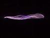
Here is my super simple low voltage version, based on Dr Stifflers SEC circuit. You'll have to forgive me, Im still new to all of this, I thought others might be interested in an easy low power, cheap to build device.
It uses 12v input @ 40-50ma, and lights up 20 5mm LEDs in series and 4 of the same on the other tower (also in series). Id like to build some more towers to see just how many loads I can place in the vicinity of the transmitting tower. It will also light up small fluro globes wirelessly when tuned correctly. Best distance to date is over 5 feet, though I think it is somewhat assisted by a surrounding metallic structure, as I cant seem to achieve those results anywhere else.
Registered Member #89
Joined: Thu Feb 09 2006, 02:40PM
Location: Zadar, Croatia
Posts: 3145
Hi guys,
At this time I'm still pondering the perfect way to extract DC power from the receiver. The most obvious is simply a fast bridge rectifier, a filter cap and a buck converter to provide constant output voltage. Still I'm somehow unconvinced this would extract maximum power available from the receiver at given point, because nothing really assures the converter is a perfect impedance match to the source. The receiver LC circuit behaves like a voltage source with significant series impedance, which I was unsure how to determine - I found it to be much higher than characteristic impedance of the LC circuit, and apparently variable with coupling. I'd be glad if someone would help me there.
Induced:
I've built a similar miniature capacitively-coupled system before - it's dug down deeply somewhere in this forum. It makes a fun experiment and may seem efficient at small scales, but is truly much more useless than magnetic counterpart.
What I'm curious about on your picture - I can't resolve any ground connections on any of your resonators. Are you using a metal sheet under the table? And what is the button-like object behind the larger LED array?
Registered Member #3011
Joined: Sun Jul 18 2010, 11:33PM
Location:
Posts: 9
Marko wrote ...
Hi guys,
At this time I'm still pondering the perfect way to extract DC power from the receiver. The most obvious is simply a fast bridge rectifier, a filter cap and a buck converter to provide constant output voltage. Still I'm somehow unconvinced this would extract maximum power available from the receiver at given point, because nothing really assures the converter is a perfect impedance match to the source. The receiver LC circuit behaves like a voltage source with significant series impedance, which I was unsure how to determine - I found it to be much higher than characteristic impedance of the LC circuit, and apparently variable with coupling. I'd be glad if someone would help me there.
Induced:
I've built a similar miniature capacitively-coupled system before - it's dug down deeply somewhere in this forum. It makes a fun experiment and may seem efficient at small scales, but is truly much more useless than magnetic counterpart.
What I'm curious about on your picture - I can't resolve any ground connections on any of your resonators. Are you using a metal sheet under the table? And what is the button-like object behind the larger LED array?
Marko
Hi Marko,
There is no metal sheet anywhere. The "transmitting" tower is a simple pulsed DC circuit using a variable inductor and capacitor for the timing. There is a coil which rises up to the elevated capacitance (aluminium cup), the load is usually placed off the collector of the transistor, in series with a 22uH inductor one wire style, with a diode plug.
I placed a small aerial off the 22uH inductor and now duplicate towers can "pick up" this signal wirelessly. The "receiving" towers are basically this:
Capacitive topload/---coil----diode plug>LED>LED>LED>etc with all LEDs in series.
Registered Member #89
Joined: Thu Feb 09 2006, 02:40PM
Location: Zadar, Croatia
Posts: 3145
Induced wrote ...
Hi Marko,
There is no metal sheet anywhere. The "transmitting" tower is a simple pulsed DC circuit using a variable inductor and capacitor for the timing. There is a coil which rises up to the elevated capacitance (aluminium cup), the load is usually placed off the collector of the transistor, in series with a 22uH inductor one wire style, with a diode plug.
I placed a small aerial off the 22uH inductor and now duplicate towers can "pick up" this signal wirelessly. The "receiving" towers are basically this:
Capacitive topload/---coil----diode plug>LED>LED>LED>etc with all LEDs in series.
Regards
Hi,
you say the led's are all in series, but the last one is connected to ''etc''? That is what I hoped you would explain.
Registered Member #3011
Joined: Sun Jul 18 2010, 11:33PM
Location:
Posts: 9
Marko wrote ...
Induced wrote ...
Hi Marko,
There is no metal sheet anywhere. The "transmitting" tower is a simple pulsed DC circuit using a variable inductor and capacitor for the timing. There is a coil which rises up to the elevated capacitance (aluminium cup), the load is usually placed off the collector of the transistor, in series with a 22uH inductor one wire style, with a diode plug.
I placed a small aerial off the 22uH inductor and now duplicate towers can "pick up" this signal wirelessly. The "receiving" towers are basically this:
Capacitive topload/---coil----diode plug>LED>LED>LED>etc with all LEDs in series.
Regards
Hi,
you say the led's are all in series, but the last one is connected to ''etc''? That is what I hoped you would explain.
Also, what is a ''diode plug''?
Marko
Hi Marko,
Sorry, the term diode plug comes from "Avramenko's plug".
It is like the drawing below, disregard the transformer action, and place the elevated capacitance (aluminium cup) on the other end of the "one wire" the end connected to nothing in this picture.
All LEDs are placed in series at the point marked "A"
Regards
PS: The thing under the main light panel is a roll of electrical tape;-)
Registered Member #89
Joined: Thu Feb 09 2006, 02:40PM
Location: Zadar, Croatia
Posts: 3145
Hi Induced,
The way you connected those led's seems very unusual to me - it's basically relying only on their stray capacitance to light them, and I'm surprised it works at all. I'm certain you would be much better off with another metal topload near the base of the receiver (and led's connected to it) - kind of like a bipolar tesla coil.
This site is powered by e107, which is released under the GNU GPL License. All work on this site, except where otherwise noted, is licensed under a Creative Commons Attribution-ShareAlike 2.5 License. By submitting any information to this site, you agree that anything submitted will be so licensed. Please read our Disclaimer and Policies page for information on your rights and responsibilities regarding this site.


 Miniature wireless power demonstrator


 That is what I hoped you would explain.