If you need assistance, please send an email to forum at 4hv dot org. To ensure your email is not marked as spam, please include the phrase "4hv help" in the subject line. You can also find assistance via IRC, at irc.shadowworld.net, room #hvcomm.
Support 4hv.org!
Donate:
4hv.org is hosted on a dedicated server. Unfortunately, this server costs and we rely on the help of site members to keep 4hv.org running. Please consider donating. We will place your name on the thanks list and you'll be helping to keep 4hv.org alive and free for everyone. Members whose names appear in red bold have donated recently. Green bold denotes those who have recently donated to keep the server carbon neutral.
Special Thanks To:
Aaron Holmes
Aaron Wheeler
Adam Horden
Alan Scrimgeour
Andre
Andrew Haynes
Anonymous000
asabase
Austin Weil
barney
Barry
Bert Hickman
Bill Kukowski
Blitzorn
Brandon Paradelas
Bruce Bowling
BubeeMike
Byong Park
Cesiumsponge
Chris F.
Chris Hooper
Corey Worthington
Derek Woodroffe
Dalus
Dan Strother
Daniel Davis
Daniel Uhrenholt
datasheetarchive
Dave Billington
Dave Marshall
David F.
Dennis Rogers
drelectrix
Dr. John Gudenas
Dr. Spark
E.TexasTesla
eastvoltresearch
Eirik Taylor
Erik Dyakov
Erlend^SE
Finn Hammer
Firebug24k
GalliumMan
Gary Peterson
George Slade
GhostNull
Gordon Mcknight
Graham Armitage
Grant
GreySoul
Henry H
IamSmooth
In memory of Leo Powning
Jacob Cash
James Howells
James Pawson
Jeff Greenfield
Jeff Thomas
Jesse Frost
Jim Mitchell
jlr134
Joe Mastroianni
John Forcina
John Oberg
John Willcutt
Jon Newcomb
klugesmith
Leslie Wright
Lutz Hoffman
Mads Barnkob
Martin King
Mats Karlsson
Matt Gibson
Matthew Guidry
mbd
Michael D'Angelo
Mikkel
mileswaldron
mister_rf
Neil Foster
Nick de Smith
Nick Soroka
nicklenorp
Nik
Norman Stanley
Patrick Coleman
Paul Brodie
Paul Jordan
Paul Montgomery
Ped
Peter Krogen
Peter Terren
PhilGood
Richard Feldman
Robert Bush
Royce Bailey
Scott Fusare
Scott Newman
smiffy
Stella
Steven Busic
Steve Conner
Steve Jones
Steve Ward
Sulaiman
Thomas Coyle
Thomas A. Wallace
Thomas W
Timo
Torch
Ulf Jonsson
vasil
Vaxian
vladi mazzilli
wastehl
Weston
William Kim
William N.
William Stehl
Wesley Venis
The aforementioned have contributed financially to the continuing triumph of 4hv.org. They are deserving of my most heartfelt thanks.
Registered Member #1506
Joined: Mon May 26 2008, 06:19PM
Location:
Posts: 18
Ok, so I think another 555 is fried again
In the tester circuit it reads continuously "high", and when pin 3 is disconnected from the resistors/LEDs both LEDs come on. Reconnecting pin 3 shuts down the "low" LED and makes the "high" LED come back on.
I changed R1 value to 1k Ohm and the R2 value to 90.2k Ohm. The C1 value was 1nF for the speaker/ignition coil test (calcs to about 8kHz), and a 1uF was added in parallel for the LED test which brings the frequency down to 8Hz. I also tried using a 9v battery as the power supply for the LED test only, and got the same test results.
So, suggestions on how to protect the 555? I kind of thought that since I was using a PC-PS, the internal regulation on it would keep voltage spikes to a minimum. Would just a filtering cap (a few uF?) placed across the supply rails be enough?
I know this is probably irrelevant now, but here is the voltage at the pins: 1: 0 2: 11.2 3: 11.1 4: 12.08 5: 11.9 6: 11.22 7: 12.08 8: 12.08
Suggestions?
Thanks, Theodore
EDIT: Ok, popped a new 555 in the breadboard, tested with both LEDs and headphones at 8Hz and 8kHz. Both tests worked just fine for extended periods of time with the PC-PS power supply, and the 8kHz tone corresponds to the tone listed as 8kHz on a youtube video. So, the logical conclusion to me is that when hooked up to the coil/FET some sort of voltage or current spike is being produced that is frying the 555s.
So, I know I can produce a circuit that generates an 8kHz signal. Now how can I get that signal to switch the MOSFET safely? Can a gate drive be used to isolate and protect the 555? Hmm, but since the coil and signal generator are running off the same 12V rail...
I dunno, need to think and research on it more. Suggestions and opinions are more than welcome. ^_^
Registered Member #30
Joined: Fri Feb 03 2006, 10:52AM
Location: Glasgow, Scotland
Posts: 6706
Theodore wrote ...
Hmm, but since the coil and signal generator are running off the same 12V rail...
This is a known problem, the high current drawn by the coil can put spikes onto the rail that will fry your 555. Most of the schematics you'll see show separate rails for the coil and the driver, and this is why. So try running the 555 off a 9v battery. But don't forget to keep the ground rail connected! There should be two wires going from your 555 to your MOSFET: Gate drive and ground.
Spikes can also feed back through the MOSFET's gate terminal, but this is harder to protect against.
Registered Member #1617
Joined: Fri Aug 01 2008, 07:31AM
Location: Adelaide, South Australia
Posts: 139
This is a known problem, the high current drawn by the coil can put spikes onto the rail that will fry your 555. Most of the schematics you'll see show separate rails for the coil and the driver, and this is why. So try running the 555 off a 9v battery. But don't forget to keep the ground rail connected! There should be two wires going from your 555 to your MOSFET: Gate drive and ground.
If your not drawing any sparks from the coil, the voltage across the primary can easily reach a few hundred volts! You can try putting some large valued zeners across the supply rail, to clamp the voltage to a reasonable level, but they will get hot if the secondary of the coil is left open circuit (no arcs), so you will probably need to use high wattage ones. I've built an ignition coil driver like this before (zeners to clamp the voltage), and it seemed to work quite well.
Registered Member #1739
Joined: Fri Oct 03 2008, 10:05AM
Location: Moscow, Russia
Posts: 261
LM7812 with full cap bypass and probably a choke to feed the 555, also a TVS across the gate isn't the worst idea. And remember, a gate resistor _is_ required, use like 50 Ohms for the lower frequencies.
Registered Member #2099
Joined: Wed Apr 29 2009, 12:22AM
Location: Los Altos, California
Posts: 1716
I like Steve's idea to run the 555 circuit from a battery -- the timer is isolated from power section except for 2 wires: GND and gate drive.
Now as for the power section (12V source, ignition coil primary, and mosfet): Normal operation depends on spikes of over 100V on the MOSFET drain. Uh - you said your fet is NTE2396, looks like its V_DS rating is 100 V ... that's a non-starter in 12V ignition coil app! Get a 400 V fet! Can probably find one in a junk PC power supply. Also, that's where the spikes automatically get higher if HV output fails to initiate a spark, as suggested by Jesse.
A real spark plug would seem to be an appropriate HV load at this stage.
But the 12V rail should not suffer spikes over 1V if it's well fed. Can you add capacitors between 12V and GND within a few inches of the ignition coil and MOSFET? Say, an Al-can electrolytic of 1000 uF or so -- you can get one from the output section of junk PS. And 1 to 10 uF ceramic cap in parallel?
Ig. coil experts: isn't 8 kHz awful fast? Is 0.06 ms on-time long enough to charge the primary inductance? An 8-cylinder engine at 6000 RPM fires only 400 times per second. How bout, for first attempt at sparks, set up the timer for on-time of 2 ms and off-time of 100 ms. Consult 555 app note for how to get narrow positive pulses.
Here is another respectable reference, if not already pointed out here: Like a previous post in this thread, he recommends a MOV between MOSFET drain and source. And I now see, he recommends starting with frequency higher than optimum (small on-time and primary coil current) then progressively reduce the freq. until output voltage stops increasing.
Registered Member #1506
Joined: Mon May 26 2008, 06:19PM
Location:
Posts: 18
Wow, thanks for all the responses guys.
For the moment I will go with powering the 555 via 9v battery, although eventually I would like to get a voltage regulator like lithium lord mentioned (and filtering cap bank) so I can run it off one supply and not have to worry about replacing batteries.
Clearly, as said by multiple people, I need a different transistor. Nothing in the local shops is good enough, I may check through some scraps, but will probably have to order some parts through digi-key.
As for the frequency, I used info at the following link: which states that the resonant frequency of the particular coil I have is 8kHz. Is it correct? I have no idea.
Hmm, interesting. In that link that Klugesmith provided, pin 7 of the 555 isnt hooked up at all. I didn't even know that was a possibility. Lots of info in that link, will take a bit to digest and decide whether to include it in mine or not.
Lastly, I had a few questions: 1. When using a battery to run the 555, am I to understand that both the 12v ground and the 9v ground are going to be connected to the 555 circuit?
2. I know this is silly, but I want to ask it anyway: Earth ground IS an appropriate place to spark the output of the ignition coil to, yes?
3. I also don't understand why the mosfet can see voltages of over 100v, but yet in 'normal operation' there shouldn't be spikes of more than +/- 1v on the supply rails?
4. I see a lot of youtube videos and the like where they are letting the hV output of the iggy strike to the primary taps on the top of the coil. I really don't understand how letting 20kV+ strike the supply rails doesn't fry all the circuitry like mosfets, 555s, supplies, etc.
I think that's about it. Need to find some parts and read some more now. More suggestions and ideas are very much welcome as always.
Registered Member #1506
Joined: Mon May 26 2008, 06:19PM
Location:
Posts: 18
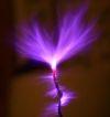
Woo, I got a spark!
Unfortunately, its not much more spark than what you get with flint and steel.
I found an IBGT on a scrap PC-PS, datasheet and specs: 600V, 54A
First I tested it by triggering the gate with a 555 but attached the LED/resistor array to the collector, and started with ~8Hz. I found that having a 10k resistor from gate to ground really dampened the oscillation of the LEDs. Also, I found that using a 9V battery as the PS would work, but again the oscillations were much weaker. I fear that I need a stronger voltage to properly "turn on" this component, I think the datasheet says 15V.
Then tested it at 8kHz, using headphones. Also worked.
Mounted the IGBT properly on the heat sink, had to adjust my fittings since there was some left over traces of solder on the pins. Hooked everything up, including 9V and 12V sharing a common ground.
And I got "sparks". More like a twinkle across a few mils of air to earth ground, but its something. Tried adjusting the frequency down to 3 or 4kHz, didn't really get anything more out of it. Added a 470uF, 220V cap scrounged from a laptop PS across the 12V rails, and the sparks definitely were brighter, although they didn't really seem to want to jump much further.
I think that if I: 1. Find this coils resonance frequency. 2. Add a 2000uF cap bank to the 12V supply. 3. Find a way to better drive the IBGT.
I might actually be able to produce 3-5cm arcs with this. However, I: 1. Don't have an oscilloscope. 2. Need to buy the caps. 3. Haven't a clue how best to accomplish this.
Registered Member #152
Joined: Sun Feb 12 2006, 03:36PM
Location: Czech Rep.
Posts: 3384
Sulaiman, what is the purpose of the 100 ohm resistor and the RC across the coil? We're trying to produce the highest voltage "kick". And with the 100ohm resistor, the output will be almost nothing.
The cap on the pin 5 can be changed to 0.1uF to better protect it from interference (I do this anyway).
Also don't forget the possibility that the coil might be fried.
This site is powered by e107, which is released under the GNU GPL License. All work on this site, except where otherwise noted, is licensed under a Creative Commons Attribution-ShareAlike 2.5 License. By submitting any information to this site, you agree that anything submitted will be so licensed. Please read our Disclaimer and Policies page for information on your rights and responsibilities regarding this site.


 555-based ignition coil, assistance requested