If you need assistance, please send an email to forum at 4hv dot org. To ensure your email is not marked as spam, please include the phrase "4hv help" in the subject line. You can also find assistance via IRC, at irc.shadowworld.net, room #hvcomm.
Support 4hv.org!
Donate:
4hv.org is hosted on a dedicated server. Unfortunately, this server costs and we rely on the help of site members to keep 4hv.org running. Please consider donating. We will place your name on the thanks list and you'll be helping to keep 4hv.org alive and free for everyone. Members whose names appear in red bold have donated recently. Green bold denotes those who have recently donated to keep the server carbon neutral.
Special Thanks To:
Aaron Holmes
Aaron Wheeler
Adam Horden
Alan Scrimgeour
Andre
Andrew Haynes
Anonymous000
asabase
Austin Weil
barney
Barry
Bert Hickman
Bill Kukowski
Blitzorn
Brandon Paradelas
Bruce Bowling
BubeeMike
Byong Park
Cesiumsponge
Chris F.
Chris Hooper
Corey Worthington
Derek Woodroffe
Dalus
Dan Strother
Daniel Davis
Daniel Uhrenholt
datasheetarchive
Dave Billington
Dave Marshall
David F.
Dennis Rogers
drelectrix
Dr. John Gudenas
Dr. Spark
E.TexasTesla
eastvoltresearch
Eirik Taylor
Erik Dyakov
Erlend^SE
Finn Hammer
Firebug24k
GalliumMan
Gary Peterson
George Slade
GhostNull
Gordon Mcknight
Graham Armitage
Grant
GreySoul
Henry H
IamSmooth
In memory of Leo Powning
Jacob Cash
James Howells
James Pawson
Jeff Greenfield
Jeff Thomas
Jesse Frost
Jim Mitchell
jlr134
Joe Mastroianni
John Forcina
John Oberg
John Willcutt
Jon Newcomb
klugesmith
Leslie Wright
Lutz Hoffman
Mads Barnkob
Martin King
Mats Karlsson
Matt Gibson
Matthew Guidry
mbd
Michael D'Angelo
Mikkel
mileswaldron
mister_rf
Neil Foster
Nick de Smith
Nick Soroka
nicklenorp
Nik
Norman Stanley
Patrick Coleman
Paul Brodie
Paul Jordan
Paul Montgomery
Ped
Peter Krogen
Peter Terren
PhilGood
Richard Feldman
Robert Bush
Royce Bailey
Scott Fusare
Scott Newman
smiffy
Stella
Steven Busic
Steve Conner
Steve Jones
Steve Ward
Sulaiman
Thomas Coyle
Thomas A. Wallace
Thomas W
Timo
Torch
Ulf Jonsson
vasil
Vaxian
vladi mazzilli
wastehl
Weston
William Kim
William N.
William Stehl
Wesley Venis
The aforementioned have contributed financially to the continuing triumph of 4hv.org. They are deserving of my most heartfelt thanks.
Registered Member #1497
Joined: Thu May 22 2008, 05:24AM
Location: Toronto, Ontario, Canada
Posts: 801
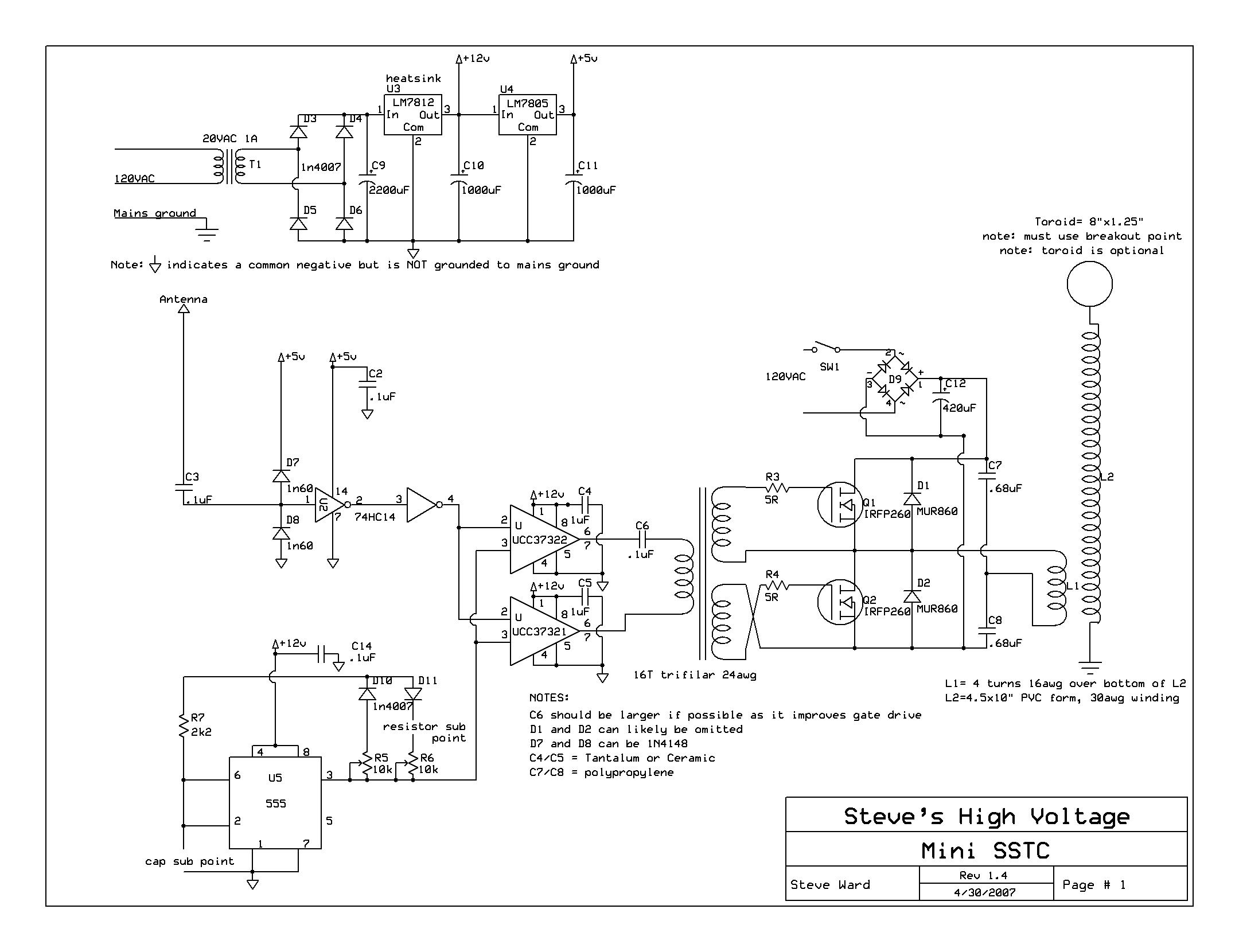
From the looks of it, its a 74hc14 based SSTC driver, that is my best guess. I'd have to comment that if you haven't etched boards before, you may want to increase the gap between ground plane and traces.
Also, consider adding mounting holes so you don't haphazardly mount your board...
And from personal experience, the 7812 regulator will need a heatsink absolutely (the 74hc14 draws next to no power, but the 2 UCC's draw a ton of power). Look at what heatsinks you have and plan the space accordingly. I believe that the tabs are connected to ground which will make heatsinking easy (ie: both can be grounded together).
Registered Member #1225
Joined: Sat Jan 12 2008, 01:24AM
Location: Beaumont, Texas, USA
Posts: 2253
I must agree with aonomous, but the heatsink need not be too terribly big, depending on your input voltage. Go to about 18 seconds to see the heatsink i used. I was using about 12.4(wayyyy too low) into the 12v regulator(still came out to exactly 12v) and it was a 500ma regulator. And, the dc blocking cap i used for the GDT sucked, and i had the wrong core, and the ucc's heated up much more than the tiny heatsink. After that video, the heatsink was a tiny bit warm, but not enough to cause any worry even for longer runs.
Registered Member #540
Joined: Mon Feb 19 2007, 07:49PM
Location: MIT
Posts: 969
You should probably tie the inputs of your other unused gates to the positive rail (I think that's what you are supposed to do because I think that they draw more current if they are tied to ground).
Registered Member #15
Joined: Thu Feb 02 2006, 01:11PM
Location:
Posts: 3068
You have to rework the ground plane. The worst thing you can is break-up the ground plane. Try desiging your board so the ground plane is pretty even across the entire board. Also, the ground plane gets really necked down between the big caps on left and your components on the right.
Also, for optimum performance, as i said before, you don't want to break-up the ground plane which you are doing with all those long traces in the middle of the board. Your better off making the board mostly ground plane and using wires to make those long trace connections as opposed to actual traces. This would be optimal for a single-layer board.
Registered Member #51
Joined: Thu Feb 09 2006, 04:17AM
Location:
Posts: 263
You need thermals. Don't leave the unused inverter gates floating. The top of your board is at a funky angle. Most if not all of your traces are way oversized.
Registered Member #1517
Joined: Wed Jun 04 2008, 06:55AM
Location: Chico CA
Posts: 304
OK whew that's a lot of stuff guys! I am actually signed up for a digital systems design course this next semester, so this is all very new to me.
You should have seen the first mock up I did, my signal traces were running all over the place. XD
As far as components go, do I have the right idea?
- I am going to put a heat sink on the back of the regulator. - all I have are 2 sided PCB's should I make the top side the ground plane and run the traces for everything else on the bottom? I am having trouble visualizing how I am going to solder some of the components without bottom traces. - vias, I take it you need to fill these with solder when the board is complete, otherwise how do you get a connection? - are the power traces thick enough? I am going to downsize the signal traces and try to run them in one direction. - i read up a bit on tying down the unused inverter gates, I will add 1k resistors to the inputs and tie them to the Vcc outputs I will leave alone
This site is powered by e107, which is released under the GNU GPL License. All work on this site, except where otherwise noted, is licensed under a Creative Commons Attribution-ShareAlike 2.5 License. By submitting any information to this site, you agree that anything submitted will be so licensed. Please read our Disclaimer and Policies page for information on your rights and responsibilities regarding this site.


 Double Check my PCB for me please!


