If you need assistance, please send an email to forum at 4hv dot org. To ensure your email is not marked as spam, please include the phrase "4hv help" in the subject line. You can also find assistance via IRC, at irc.shadowworld.net, room #hvcomm.
Support 4hv.org!
Donate:
4hv.org is hosted on a dedicated server. Unfortunately, this server costs and we rely on the help of site members to keep 4hv.org running. Please consider donating. We will place your name on the thanks list and you'll be helping to keep 4hv.org alive and free for everyone. Members whose names appear in red bold have donated recently. Green bold denotes those who have recently donated to keep the server carbon neutral.
Special Thanks To:
Aaron Holmes
Aaron Wheeler
Adam Horden
Alan Scrimgeour
Andre
Andrew Haynes
Anonymous000
asabase
Austin Weil
barney
Barry
Bert Hickman
Bill Kukowski
Blitzorn
Brandon Paradelas
Bruce Bowling
BubeeMike
Byong Park
Cesiumsponge
Chris F.
Chris Hooper
Corey Worthington
Derek Woodroffe
Dalus
Dan Strother
Daniel Davis
Daniel Uhrenholt
datasheetarchive
Dave Billington
Dave Marshall
David F.
Dennis Rogers
drelectrix
Dr. John Gudenas
Dr. Spark
E.TexasTesla
eastvoltresearch
Eirik Taylor
Erik Dyakov
Erlend^SE
Finn Hammer
Firebug24k
GalliumMan
Gary Peterson
George Slade
GhostNull
Gordon Mcknight
Graham Armitage
Grant
GreySoul
Henry H
IamSmooth
In memory of Leo Powning
Jacob Cash
James Howells
James Pawson
Jeff Greenfield
Jeff Thomas
Jesse Frost
Jim Mitchell
jlr134
Joe Mastroianni
John Forcina
John Oberg
John Willcutt
Jon Newcomb
klugesmith
Leslie Wright
Lutz Hoffman
Mads Barnkob
Martin King
Mats Karlsson
Matt Gibson
Matthew Guidry
mbd
Michael D'Angelo
Mikkel
mileswaldron
mister_rf
Neil Foster
Nick de Smith
Nick Soroka
nicklenorp
Nik
Norman Stanley
Patrick Coleman
Paul Brodie
Paul Jordan
Paul Montgomery
Ped
Peter Krogen
Peter Terren
PhilGood
Richard Feldman
Robert Bush
Royce Bailey
Scott Fusare
Scott Newman
smiffy
Stella
Steven Busic
Steve Conner
Steve Jones
Steve Ward
Sulaiman
Thomas Coyle
Thomas A. Wallace
Thomas W
Timo
Torch
Ulf Jonsson
vasil
Vaxian
vladi mazzilli
wastehl
Weston
William Kim
William N.
William Stehl
Wesley Venis
The aforementioned have contributed financially to the continuing triumph of 4hv.org. They are deserving of my most heartfelt thanks.
Registered Member #1858
Joined: Fri Dec 12 2008, 05:17AM
Location:
Posts: 9
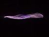
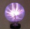
Hi I'm trying to build my first HV circuit using a flyback transformer I extracted from a somewhat old CRT TV. I'm looking to build a 555 timer-based driver first and then possibly move onto a ZVS driver. So my big problem right now is identifying the primary and secondary coils on my flyback and figuring out how they should be configured. I don't understand what's going on when I see flybacks like mine with coils added on the outside bar. Is that a newly wound primary? Do I want to do this? I'll just assume for now I want to leave my flyback as is. Regardless of what driver I use are the output terminals located on the suction cup and the 0V point on the secondary? The two methods I've found for finding the 0V point are from http://leoricksimon.blogspot.com/2007/05/flyback-driver.html and http://jnaudin.free.fr/lifters/labhvps/tht.htm. The first method involves using a high resistance-reading multimeter, which I don't have and the second involves a 24VDC power supply, which I don't have on hand right now either. Is it possible for anyone to identify which pin is which by looking at my pictures before I set out to build a 24VDC power supply? I think I've got the primary right though. Isn't it polarity sensitive? The 555 timer driver I plan to use is from http://www.electronics-lab.com/projects/misc/016/index.html. Does this look good? Any response would be greatly appreciated.
Registered Member #1107
Joined: Thu Nov 08 2007, 10:09PM
Location:
Posts: 792
Don't waist your time finding the existing primary coils. Just wind your own of 10-12 turns on the opposite exposed core section. The suction cup is the hv anode (hv +) and the hv ground is one of the pins on the bottom of the flyback. The easiest way to find out what pin it is, is to get the driver working and then by bringing the hv anode wire near the bottom pins, the one that it arcs to the most is the 0v pin. I hope this helps.
Registered Member #1790
Joined: Fri Oct 31 2008, 10:10AM
Location: Sydney, Australia
Posts: 40
Hi,
I think you will be better off by just winding your own primary on the exposed part of the ferrite core. There seems to be enough room to wind it.
For the HV ground identification, just bring the big red wire near the pinout at the bottom and , it should start arcing to gnd when you turn the driver on.
Registered Member #1225
Joined: Sat Jan 12 2008, 01:24AM
Location: Beaumont, Texas, USA
Posts: 2253
Hello, and welcome to the forum! Well, to find the primary, just use either inductance meter, resistance meter, or a simple light in series with a power supply with same rated voltage as the bulb. Just scan the leads, and the one with lowest inductance or resistance is the best primary. If you do not have either of those, you can put some sort of low current load(lightbulb or small dc motor) in series with the output of a power supply rated for the load. When even you find two pins that have continuity, it would be a primary. You will probably find two low resistance windings, and one high one. The lowest resistance is better.
You can just wind your own primary though. For a 555 driver, around 10 turns will do fine. The internal primary seems to work better for me though. If you still have the circuit board that it came off of, look on the bottom side where the flyback pins came from, and it might have markings telling you what are primaries, etc. To find the hv return(0v, what ever you want to call it) pin, just bring the hv wire close to it and the one it arcs to readily is it. Do not let it hit the wires from the driver though.
The ZVS is very simple but the ultimate simple flyback driver. It creates such little heat it is truly amazing. On my ZVS running at around 600-800 watts, the 12 gauge wires heat up more than the mosfets! Also, once i had an arc hit the wire leading to the mosfet, and it did not die. Nothing was damaged! The strangest thing is that i am using a 4 amp bridge rectifier, which does not die after a few minutes of running, even though i pull about 18.5 amps max, and 15 amps continuous. But be careful, when using the ZVS at higher powers, expect to kill some flybacks. Not because of excessive voltage, it is the current and heating that kills it! And it was the diodes most of the time on mine. I killed 3 flybacks yesterday, as well as a homemade one, and i killed one today :).
Registered Member #135
Joined: Sat Feb 11 2006, 12:06AM
Location: Anywhere is fine
Posts: 1735
You have the correct primary there! surprised?
I had a driver of exactly what you're talking about on my webpage...unfortunately... aol killed it, but I can see if I have the pictures buried somewhere if you like.
Registered Member #162
Joined: Mon Feb 13 2006, 10:25AM
Location: United Kingdom
Posts: 3141
I prefer flyback mode myself, you can push a lot of power through a flyback transformer using zvs, but there is very little protection for the very fragile secondary winding and diodes, and the output voltage is fixed at maximum continuously. A simple 555 driving a mosfet or igbt won't be as impressive, but it is more reliable, and the output power is usually easily adjustable. You must protect the switching transistor for reliability - a snubber or clamp or resonant cap is required (or an avalanche rated transistor and a big heatsink) - I always use a diode clamp for the gate to 555 0V and +V. - a fuse between the transistor and the dc smoothing/reservoir cap is a good idea. The most efficient operation will be using the original secondary winding because it is closely coupled (magnetically) to the secondary so there is less leakage flux energy to dissipate each transistor turn-off. Unfortunately this means about 100 to 150 V dc supply which is neither convenient (unless you have 110-120 Vac supply) , nor 'safe'. So initially you should wind an external primary as advised above. That way everything can be powered by a battery or low voltage psu.
Registered Member #152
Joined: Sun Feb 12 2006, 03:36PM
Location: Czech Rep.
Posts: 3384
Sulaiman wrote ...
The most efficient operation will be using the original secondary winding because it is closely coupled (magnetically) to the secondary so there is less leakage flux energy to dissipate each transistor turn-off.
Just to clear things up a bit, if you're gonna draw arcs from the transformer (and I think you are ) , then you absolutely NEED the leakage inductance if you don't want to bake something. So, winding the the primary opposite the secondary has these advantages: 1) the resulting leakage is usually about right for normal arc-drawing or other projects, 2) if it smokes you can wind a new one. If you fry the internal one, not only you can't rewind it, but usually the whole transformer is ruined because the winding often contains shorted turns.
For flyback-mode TV transformer driver, I prefer to use this one (the QR driver as I call it, you can get very high voltages out of the transformer. I also have a schematic with smps IC which allows control of output power, just let me know if you want to see it)
Registered Member #1858
Joined: Fri Dec 12 2008, 05:17AM
Location:
Posts: 9
Thanks for all of your replies! I'm going to wind my own primary and order the parts for both a 555 and ZVS driver. I have 18AWG enameled magnet wire, will this work for the primary? I plan on using the schematic suggested by Mr. Kilovolt. When you wind your own primary how do you tell which end is (+) and which is (-)? Will 1/4W resistors work? Must the 555 timer voltage be 15V? I have a 12V @ 2.5A power supply on hand, will that work? As for the ZVS driver, what wattage should the 10K resistors be rated at? What is the function of inductor coming off of the centertap? Does its inductance depend upon your power supply/primary windings or will anything between 47 and 200uH work? Should I be looking under power inductors to find it online? Should I be looking for 400+V diodes and not rectifiers, or will they function the same? One other thing I'm not so sure about is what power supply to use for the ZVS. So no matter what voltage between 10 and 40V I select, it must be able to pump out 10 or more amps? And does more voltage mean more primary coils? Does anyone have any power supply/primary combos they can share?
Registered Member #152
Joined: Sun Feb 12 2006, 03:36PM
Location: Czech Rep.
Posts: 3384
Cwiber92 wrote ...
Thanks for all of your replies! I'm going to wind my own primary and order the parts for both a 555 and ZVS driver. I have 18AWG enameled magnet wire, will this work for the primary? I plan on using the schematic suggested by Mr. Kilovolt. When you wind your own primary how do you tell which end is (+) and which is (-)? Will 1/4W resistors work? Must the 555 timer voltage be 15V? I have a 12V @ 2.5A power supply on hand, will that work?
I would suggest an insulated PVC wire for the primary, it does not need to be very thick (standard "bell wire" will work). You can use enameled too but the insulation can easily get dented by the sharp edges of the ferrite core. All resistors are 1/4W.
As for the polarity, just try both and use the one which gives bigger spark.
12V will work too (you can decrease the gate resistor to 560 ohms).
I'd suggest starting with lower voltages for the power part (e.g.12V) and then go higher, the absolute maximum is around 35 volts with the components as in the schematic. The driver can draw up to 200W so make sure your PSU can handle it.
This site is powered by e107, which is released under the GNU GPL License. All work on this site, except where otherwise noted, is licensed under a Creative Commons Attribution-ShareAlike 2.5 License. By submitting any information to this site, you agree that anything submitted will be so licensed. Please read our Disclaimer and Policies page for information on your rights and responsibilities regarding this site.


 Need help getting started on HV


 ) , then you absolutely NEED the leakage inductance if you don't want to bake something.