If you need assistance, please send an email to forum at 4hv dot org. To ensure your email is not marked as spam, please include the phrase "4hv help" in the subject line. You can also find assistance via IRC, at irc.shadowworld.net, room #hvcomm.
Support 4hv.org!
Donate:
4hv.org is hosted on a dedicated server. Unfortunately, this server costs and we rely on the help of site members to keep 4hv.org running. Please consider donating. We will place your name on the thanks list and you'll be helping to keep 4hv.org alive and free for everyone. Members whose names appear in red bold have donated recently. Green bold denotes those who have recently donated to keep the server carbon neutral.
Special Thanks To:
Aaron Holmes
Aaron Wheeler
Adam Horden
Alan Scrimgeour
Andre
Andrew Haynes
Anonymous000
asabase
Austin Weil
barney
Barry
Bert Hickman
Bill Kukowski
Blitzorn
Brandon Paradelas
Bruce Bowling
BubeeMike
Byong Park
Cesiumsponge
Chris F.
Chris Hooper
Corey Worthington
Derek Woodroffe
Dalus
Dan Strother
Daniel Davis
Daniel Uhrenholt
datasheetarchive
Dave Billington
Dave Marshall
David F.
Dennis Rogers
drelectrix
Dr. John Gudenas
Dr. Spark
E.TexasTesla
eastvoltresearch
Eirik Taylor
Erik Dyakov
Erlend^SE
Finn Hammer
Firebug24k
GalliumMan
Gary Peterson
George Slade
GhostNull
Gordon Mcknight
Graham Armitage
Grant
GreySoul
Henry H
IamSmooth
In memory of Leo Powning
Jacob Cash
James Howells
James Pawson
Jeff Greenfield
Jeff Thomas
Jesse Frost
Jim Mitchell
jlr134
Joe Mastroianni
John Forcina
John Oberg
John Willcutt
Jon Newcomb
klugesmith
Leslie Wright
Lutz Hoffman
Mads Barnkob
Martin King
Mats Karlsson
Matt Gibson
Matthew Guidry
mbd
Michael D'Angelo
Mikkel
mileswaldron
mister_rf
Neil Foster
Nick de Smith
Nick Soroka
nicklenorp
Nik
Norman Stanley
Patrick Coleman
Paul Brodie
Paul Jordan
Paul Montgomery
Ped
Peter Krogen
Peter Terren
PhilGood
Richard Feldman
Robert Bush
Royce Bailey
Scott Fusare
Scott Newman
smiffy
Stella
Steven Busic
Steve Conner
Steve Jones
Steve Ward
Sulaiman
Thomas Coyle
Thomas A. Wallace
Thomas W
Timo
Torch
Ulf Jonsson
vasil
Vaxian
vladi mazzilli
wastehl
Weston
William Kim
William N.
William Stehl
Wesley Venis
The aforementioned have contributed financially to the continuing triumph of 4hv.org. They are deserving of my most heartfelt thanks.
Registered Member #15
Joined: Thu Feb 02 2006, 01:11PM
Location:
Posts: 3068
Austin wrote ...
I didn't notice this just till now but R10 is open because it said "Not Used" in the parts list however in the schematic it shows a 10k resistor.
I still get nothing out of pin 3 of U4 even after removing R9 and C9 and R10
Then something is hooked up incorrectly and/or you have a wrong part in there. If you are getting a trigger signal into pin 2, then you should be getting an output signal. I'd do the following:
1. Disconnect what the output of the 555 is feeding into. To ensure nothing up chain is preventing it from outputting.
2. Check your resistor and capacitor values which are connected to the 555 as well as the Vcc into the 555.
3. Read the 555 tutorial located here to get a better understanding of 555's.
This circuit is about as easy / foolproof as it comes. No reason you shouldn't be getting no output unless you have a bad part / value or something.
Registered Member #1169
Joined: Wed Dec 12 2007, 09:16AM
Location: Portland OR
Posts: 251
Ok daniel I just went through every resistor, Cap, and Diode to make sure everything is properly in place. Other than the error i found earlier in the schematic, everything seems correct. I lifted up Pin 3 on U4 to see if something else was affecting the output. I still get no output out of U4.
I am getting a good trigger signal into pin 2. R9, C10 and R10 have been removed as suggested. Pin 8 is receiving approx 7 volts and Pin 5 is receiving approximately 4 volts. pot 19 is set to its max value as well.
Registered Member #141
Joined: Sat Feb 11 2006, 01:14PM
Location: Southern California
Posts: 96
I didn't notice this just till now but R10 is open because it said "Not Used" in the parts list however in the schematic it shows a 10k resistor
I'm confused. Should r10 be a 10k resistor or should it be open? I just finished building my xenosonic, and I'm also having problems. I'm getting audio in, and the leds move in response, but nothing at the output.
Registered Member #15
Joined: Thu Feb 02 2006, 01:11PM
Location:
Posts: 3068
R10 should be open. All R9 and R10 is form is a voltage divider into pin 5 of the 555.
With R10 open, you get the full voltage into pin 5. With R10 in, you get 1/2 the voltage into pin 5.
You're probably not getting anything in as you probably don't have enough gain as set by R3. This should be cranked up so you have at least 6V at pin 5 of the 555 when a note is being played.
As stated in the instructions, you should have nominally 7V during a nominal note during playback at pin 5 of the 555.
Registered Member #1169
Joined: Wed Dec 12 2007, 09:16AM
Location: Portland OR
Posts: 251
Daniel R56 in the schematic says 100k ohm resistor but the parts list calls for 1.0M ohm resistor. Which one is it?
I have performed all all suggestions you have given me, and still I get no output from Pin 3 of U4. And now someone else is experiencing the same difficulties as me. Would it be possible for you to double check your schematic and post an updated version because there are clearly quite a few discrepancies between the schematic and the parts list. or should I just go completely off the schematic and ignore the parts list.
Registered Member #15
Joined: Thu Feb 02 2006, 01:11PM
Location:
Posts: 3068
Schematic is correct other than R10, which should initially be "open."
Again, the 555 timer is a very simple device and virtually fool proof. If you aren't getting output, than something is fundamentally wrong in your circuit. Here is the list you need to check out:
1. R18, R19, and C18 are not correct. In particular, check (which means MEASURE out of circuit) that R19 is not shorted - as pots do have a habit of shorting out as a failure.
2. Trigger pulse present: Trigger needs to go less than 1/3 Vcc voltage to trigger. MEASURE with oscilloscope.
3. Control voltage at pin 5. Still not enough. Check your input signal. What is the amplitude of that signal? Maybe your computer output isn't putting out enough? Try switching to the headphone jack and try that as well.
4. Just not reading your oscilloscope properly. At 500Hz, the period is 2ms. If you don't have the timescale properly set, especially with analog scope, you may miss a short 50us pulsewidth.
I'm still betting you're not getting the proper control voltage or that R19 is bad.
I've already fielded about 50 of these units for a variety of groups, and all have shown demonstration level success including a local boy scout troop who built 10 units (for 10 DRSSTCs they have).
If its still a problem, just send it back to me and i'll troubleshoot it for you free of charge (minus shipping of course)
Registered Member #15
Joined: Thu Feb 02 2006, 01:11PM
Location:
Posts: 3068
Austin wrote ...
ok Daniel thank you for the support, I will give those suggestions a shot please stand by.
quick question tho, what did you mean by R18 and C18 is wrong? and what should the voltage be at pin 5 even with R9 and C9 removed?
R18+R19 and C18 are the RC values which determine the length of the output pulse. If R19 was shorted, for example, you'd only have R18 and C18 as your timing components leading to an almost zero length pulse.
With R9 and C9 removed, the voltage at pin 5 should be 2/3 Vcc.
As I said before, you should take a look at the following link which describes everything you need to know about a 555 timer.
The 555 in your circuit is working as a monostable operation as described in the tutorial. That is for each trigger input, it only puts out a single pulse.
Registered Member #1169
Joined: Wed Dec 12 2007, 09:16AM
Location: Portland OR
Posts: 251
Ok Daniel its working however i'm still getting noise/static in the signal. I was running a stereo .mid song which could be part of the problem. However the xenosonic makes my coil oscillate even if there is no audio input to the coil. This makes me believe there is something wrong. Any suggestions?
here is a video to show what im talking about. notice how the coil runs even if there is no audio input to the xenosonic.
Registered Member #480
Joined: Thu Jul 06 2006, 07:08PM
Location: North America
Posts: 644
Austin -
For all those who have been following your tribulations with this coil, what did you do that finally got it running? Found a wrong component value, a soldering defect, or something else? In your previous update on coil performance (Sunday, May 11) you mentioned that you still were not getting any output from U4. Suddenly on July 9th the coil is working.
This site is powered by e107, which is released under the GNU GPL License. All work on this site, except where otherwise noted, is licensed under a Creative Commons Attribution-ShareAlike 2.5 License. By submitting any information to this site, you agree that anything submitted will be so licensed. Please read our Disclaimer and Policies page for information on your rights and responsibilities regarding this site.


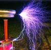
 XenoSonic Construction / Troubleshooting