If you need assistance, please send an email to forum at 4hv dot org. To ensure your email is not marked as spam, please include the phrase "4hv help" in the subject line. You can also find assistance via IRC, at irc.shadowworld.net, room #hvcomm.
Support 4hv.org!
Donate:
4hv.org is hosted on a dedicated server. Unfortunately, this server costs and we rely on the help of site members to keep 4hv.org running. Please consider donating. We will place your name on the thanks list and you'll be helping to keep 4hv.org alive and free for everyone. Members whose names appear in red bold have donated recently. Green bold denotes those who have recently donated to keep the server carbon neutral.
Special Thanks To:
Aaron Holmes
Aaron Wheeler
Adam Horden
Alan Scrimgeour
Andre
Andrew Haynes
Anonymous000
asabase
Austin Weil
barney
Barry
Bert Hickman
Bill Kukowski
Blitzorn
Brandon Paradelas
Bruce Bowling
BubeeMike
Byong Park
Cesiumsponge
Chris F.
Chris Hooper
Corey Worthington
Derek Woodroffe
Dalus
Dan Strother
Daniel Davis
Daniel Uhrenholt
datasheetarchive
Dave Billington
Dave Marshall
David F.
Dennis Rogers
drelectrix
Dr. John Gudenas
Dr. Spark
E.TexasTesla
eastvoltresearch
Eirik Taylor
Erik Dyakov
Erlend^SE
Finn Hammer
Firebug24k
GalliumMan
Gary Peterson
George Slade
GhostNull
Gordon Mcknight
Graham Armitage
Grant
GreySoul
Henry H
IamSmooth
In memory of Leo Powning
Jacob Cash
James Howells
James Pawson
Jeff Greenfield
Jeff Thomas
Jesse Frost
Jim Mitchell
jlr134
Joe Mastroianni
John Forcina
John Oberg
John Willcutt
Jon Newcomb
klugesmith
Leslie Wright
Lutz Hoffman
Mads Barnkob
Martin King
Mats Karlsson
Matt Gibson
Matthew Guidry
mbd
Michael D'Angelo
Mikkel
mileswaldron
mister_rf
Neil Foster
Nick de Smith
Nick Soroka
nicklenorp
Nik
Norman Stanley
Patrick Coleman
Paul Brodie
Paul Jordan
Paul Montgomery
Ped
Peter Krogen
Peter Terren
PhilGood
Richard Feldman
Robert Bush
Royce Bailey
Scott Fusare
Scott Newman
smiffy
Stella
Steven Busic
Steve Conner
Steve Jones
Steve Ward
Sulaiman
Thomas Coyle
Thomas A. Wallace
Thomas W
Timo
Torch
Ulf Jonsson
vasil
Vaxian
vladi mazzilli
wastehl
Weston
William Kim
William N.
William Stehl
Wesley Venis
The aforementioned have contributed financially to the continuing triumph of 4hv.org. They are deserving of my most heartfelt thanks.
Registered Member #834
Joined: Tue Jun 12 2007, 10:57PM
Location: Brazil
Posts: 644
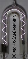
To determine the voltage precisely, produce sparks between balls. The spark length between points depends on many details, and is easily 3 times longer. This is 20 kV:
A good formula for the voltage for a spark between two identical balls is:
Registered Member #964
Joined: Wed Aug 22 2007, 12:39AM
Location: Stockton, CA
Posts: 134
Dr. Monsterarc wrote ...
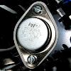
Here is the promised run with a DC flyback Approx. 40kV. I used: 390R/2W, 10(!)R/6W, 8 pri. turns, 3 feedback turns, 0.56uF cap, KD606 transistor (made by "Tesla", long discontinued, but it's the best transistor for the single transistor driver I ever had...) gets just little warm after short runs.
I'll try to remove some primary turns and set the operating point so I get more kV out with the same power...
So you mean the 390R/2W at the 'top' of the schem. and the 10R/6W at the bottom, right?
Registered Member #690
Joined: Tue May 08 2007, 03:47AM
Location: New Jersey, USA
Posts: 616
Antonio, where on earth did you find that formula!? That's a nice one; it sure takes things further than just 1.1kv/mm like i usually use to "measure" voltage.
I think it deserves this though, for ease of understanding:
Registered Member #152
Joined: Sun Feb 12 2006, 03:36PM
Location: Czech Rep.
Posts: 3384
Spedy wrote ...
So you mean the 390R/2W at the 'top' of the schem. and the 10R/6W at the bottom, right?
yeah
--- what I found out: More feedback turns=more power (but not necesarilly more voltage). Decreasing the value of bottom resistor results in more power and voltage, but the resistor WILL get very hot if you get it too small. The top resistor has minimal effect on performance, so it is best to use the highest value that allows for reliable start-up. Bigger capacitors tend to produce hotter arcs possibly with decreased output voltage.
Registered Member #1408
Joined: Fri Mar 21 2008, 03:49PM
Location: Oracle, AZ
Posts: 679
Dr. Monsterarc wrote ...
Decreasing the value of bottom resistor results in more power and voltage, but the resistor WILL get very hot if you get it too small. The top resistor has minimal effect on performance, so it is best to use the highest value that allows for reliable start-up. Bigger capacitors tend to produce hotter arcs possibly with decreased output voltage.
You bring up a very interesting point from what I am just studying. When I was looking at the circuit I believe those resistors to be functioning in parallel even though they exist in a series of two (one after another). If I'm correct and they are functioning in parallel, their collective value will be lower than the lowest one of the two.
Example: We have two resistors, a 22 ohm & a 470 which = 492ohm but the actual resistance would be 21 ohm if they are used as parallel with our circuit. But if we didn't have a 22 & 470 but a 92 & a 400 ohm we would have 75.1 total resistance. I tried playing with the values and that gave me the idea that they were functioning in parallel. If I'm right we could use two resistors & depending upon the values of each those choices would determine the functionality. So this concept playing itself out to the fullest - if we had a 600 & a 20 ohm, our total resistance would be 19.3 ohms....even less than the 470 & 22 original design.
{I also was wondering what you meant by the term "big" in capacitors; voltage or storage...? As I'd like to experiment with that.}
Registered Member #964
Joined: Wed Aug 22 2007, 12:39AM
Location: Stockton, CA
Posts: 134
Hmm, this could present a problem for me. What if I paralleled a ton of resistors of the same value to get a higher wattage, would the resistance change? Ex: 10x 10ohms in parallel would = less than 10ohms?
Registered Member #10
Joined: Thu Feb 02 2006, 09:45AM
Location: Bunbury, Australia
Posts: 1424
This circuit has been around for a long time. I got my circuit from Sam Barros' site and made it up in 2002. Draws 3 A at 20V with 2N3055 for 1/2 inch spark.
Registered Member #834
Joined: Tue Jun 12 2007, 10:57PM
Location: Brazil
Posts: 644
Shaun wrote ...
Antonio, where on earth did you find that formula!? That's a nice one; it sure takes things further than just 1.1kv/mm like i usually use to "measure" voltage.
I think it deserves this though, for ease of understanding:
The formula comes from this document ("North report"): It is said there that the formula is exact, but it isn't. It is a good approximation, however. The exact expression has an infinite series.
Registered Member #952
Joined: Mon Aug 13 2007, 11:07AM
Location: Finland
Posts: 388
I made a 555 based single MOSFET driver and started with a 440nF cap across the FET. The arc started at 5mm and stretched to 25mm. Then I removed 220nF from the capacitance and the arcs started at 20mm and drawed to 50mm! So tuning is very important.
Registered Member #2443
Joined: Wed Oct 21 2009, 06:08PM
Location:
Posts: 1
Apologies for the thread necromancy, but I figured it was better than posting an all-new thread just for my question;
I'm a newbie. I built the 2n3055 circuit on the wiki, it worked, but they were right to say it leaves you wanting more. So I tried to build this one, with the materials to hand.
The materials at hand are a 2SD1555 transistor (built in damper diode, ~5V threshold voltage) and a 12V power supply. And it doesn't work.
My suspicion is that I'm not delivering enough voltage to turn the transistor on, but I've got no idea how to modify the circuit to fix this. Can anyone help?
(explainations of why the changes you suggest would fix it would be appreciated as well, so that I can actually start to understand what I'm building)
This site is powered by e107, which is released under the GNU GPL License. All work on this site, except where otherwise noted, is licensed under a Creative Commons Attribution-ShareAlike 2.5 License. By submitting any information to this site, you agree that anything submitted will be so licensed. Please read our Disclaimer and Policies page for information on your rights and responsibilities regarding this site.


 Improved single transistor flyback driver