If you need assistance, please send an email to forum at 4hv dot org. To ensure your email is not marked as spam, please include the phrase "4hv help" in the subject line. You can also find assistance via IRC, at irc.shadowworld.net, room #hvcomm.
Support 4hv.org!
Donate:
4hv.org is hosted on a dedicated server. Unfortunately, this server costs and we rely on the help of site members to keep 4hv.org running. Please consider donating. We will place your name on the thanks list and you'll be helping to keep 4hv.org alive and free for everyone. Members whose names appear in red bold have donated recently. Green bold denotes those who have recently donated to keep the server carbon neutral.
Special Thanks To:
Aaron Holmes
Aaron Wheeler
Adam Horden
Alan Scrimgeour
Andre
Andrew Haynes
Anonymous000
asabase
Austin Weil
barney
Barry
Bert Hickman
Bill Kukowski
Blitzorn
Brandon Paradelas
Bruce Bowling
BubeeMike
Byong Park
Cesiumsponge
Chris F.
Chris Hooper
Corey Worthington
Derek Woodroffe
Dalus
Dan Strother
Daniel Davis
Daniel Uhrenholt
datasheetarchive
Dave Billington
Dave Marshall
David F.
Dennis Rogers
drelectrix
Dr. John Gudenas
Dr. Spark
E.TexasTesla
eastvoltresearch
Eirik Taylor
Erik Dyakov
Erlend^SE
Finn Hammer
Firebug24k
GalliumMan
Gary Peterson
George Slade
GhostNull
Gordon Mcknight
Graham Armitage
Grant
GreySoul
Henry H
IamSmooth
In memory of Leo Powning
Jacob Cash
James Howells
James Pawson
Jeff Greenfield
Jeff Thomas
Jesse Frost
Jim Mitchell
jlr134
Joe Mastroianni
John Forcina
John Oberg
John Willcutt
Jon Newcomb
klugesmith
Leslie Wright
Lutz Hoffman
Mads Barnkob
Martin King
Mats Karlsson
Matt Gibson
Matthew Guidry
mbd
Michael D'Angelo
Mikkel
mileswaldron
mister_rf
Neil Foster
Nick de Smith
Nick Soroka
nicklenorp
Nik
Norman Stanley
Patrick Coleman
Paul Brodie
Paul Jordan
Paul Montgomery
Ped
Peter Krogen
Peter Terren
PhilGood
Richard Feldman
Robert Bush
Royce Bailey
Scott Fusare
Scott Newman
smiffy
Stella
Steven Busic
Steve Conner
Steve Jones
Steve Ward
Sulaiman
Thomas Coyle
Thomas A. Wallace
Thomas W
Timo
Torch
Ulf Jonsson
vasil
Vaxian
vladi mazzilli
wastehl
Weston
William Kim
William N.
William Stehl
Wesley Venis
The aforementioned have contributed financially to the continuing triumph of 4hv.org. They are deserving of my most heartfelt thanks.
Registered Member #1223
Joined: Thu Jan 10 2008, 04:32PM
Location:
Posts: 133
Harry wrote ...
Xc 0.1uF @ 450kHz = 3R537 - a nice low reactance at fo - no more to it than that
The tuned circuit values given in the diagram - 63uH and 0.002uF - correspond to fo = 448.368418kHz
I just cant find suitable caps rated 100nF/5..10kV. MMC, no thanks. I want to use either ceramic or mica caps and there is no 100nF/5kV ceramics available with enough kvar. So i have to use 10nF and I think it is just fine.
Registered Member #543
Joined: Tue Feb 20 2007, 04:26PM
Location: UK
Posts: 4992
Tonskulus wrote ...
Harry wrote ...
Xc 0.1uF @ 450kHz = 3R537 - a nice low reactance at fo - no more to it than that
The tuned circuit values given in the diagram - 63uH and 0.002uF - correspond to fo = 448.368418kHz
I just cant find suitable caps rated 100nF/5..10kV. MMC, no thanks. I want to use either ceramic or mica caps and there is no 100nF/5kV ceramics available with enough kvar. So i have to use 10nF and I think it is just fine.
Costly parts, to be sure, but they are certainly available.
Registered Member #30
Joined: Fri Feb 03 2006, 10:52AM
Location: Glasgow, Scotland
Posts: 6706
DC block capacitors don't need a kVAr rating. We size them so the impedance is negligible (and Harry verified this for us) therefore the RF voltage across them is negligible, therefore so also is the kVAr, since it's the product of RF voltage and RF current.
By all means try 0.01uF, but don't come crying to us if it starts squegging
Registered Member #1223
Joined: Thu Jan 10 2008, 04:32PM
Location:
Posts: 133
Steve McConner wrote ...
DC block capacitors don't need a kVAr rating. We size them so the impedance is negligible (and Harry verified this for us) therefore the RF voltage across them is negligible, therefore so also is the kVAr, since it's the product of RF voltage and RF current.
By all means try 0.01uF, but don't come crying to us if it starts squegging
About 30ohm reactance for 10nF @ 450kHz is not so much in this case. Voltage is high and max current is 500mA. And 10nF is just so common value i have seen in commerical induction heater units..
Anyway, my first vtih uses only 5nF dc block capacitor and it is working very well as can be seen on my videos.
btw, i fixed those links in first post, so pictures are now available again ;)
Registered Member #543
Joined: Tue Feb 20 2007, 04:26PM
Location: UK
Posts: 4992
I can't help feeling that the values of components in valve circuits should be individually calculated to suit both the valve and the application.
In considering substitutions in circuits of this kind, one should reverse engineer the original designer's calculations to see why particular values were chosen. Selection shouldn't be arbitrary!
In the case of the 0.1uF capacitor, it presents an agreeably low reactance at signal frequency without becoming prohibitively large and expensive and risking unwanted inductive effects - objectionable self-resonances, odious unwanted oscillations, and so on. The self-resonance of capacitors is always an important component selection criterion in RF design.
May I suggest that this circuit diagram may perhaps be a 'skeleton' circuit - lacking in design detail for the sake of simplicity like a textbook illustration? I have no experience whatsoever of induction heating, but the following ideas occur:
The load may fluctuate wildly - for example, when the Curie temperature of the work is reached.
The oscillator frequency will definitely start 'pulling' as power is drawn from the circuit, perhaps causing de-tuning power loss.
This circuit has been designed for use with a large, complex, variable HV supply, since the existence of cathode and grid current meters implies the ability to alter the valve operating parameters in a way that is not shown in the circuit diagram.
Registered Member #1223
Joined: Thu Jan 10 2008, 04:32PM
Location:
Posts: 133
Harry wrote ...
May I suggest that this circuit diagram may perhaps be a 'skeleton' circuit - lacking in design detail for the sake of simplicity like a textbook illustration? I have no experience whatsoever of induction heating, but the following ideas occur:
The load may fluctuate wildly - for example, when the Curie temperature of the work is reached.
The oscillator frequency will definitely start 'pulling' as power is drawn from the circuit, perhaps causing de-tuning power loss.
This circuit has been designed for use with a large, complex, variable HV supply, since the existence of cathode and grid current meters implies the ability to alter the valve operating parameters in a way that is not shown in the circuit diagram.
Powersupply is not variable. To get maximum power and efficiency, there has to be plate current meter to see how much power is induced to the workpiece. Let me tell you: Ok lets think about LCR circuit in tube oscillator. If there is no R (tank circuit losses and workcoil load), Current and voltage has exactly 180deg phase difference = no power is required. But as there is always tank losses, small amount of power is needed anyway. So, without load in workcoil, plate current is at minimum. When workpiece is inserted to workcoil, this adds more R to the tank circuit. Thus, tube is trying to keep tank current constant and because workpiece now adds some phase shift, more power is needed. Plate current increases. Now, we have two plate current readings. No load current and loaded current. This current difference * plate voltage = total induced power. Thus, plate current meter is very good tool there. When designing workcoils, we just try to get maximum possible no load/load current difference. Im not sure why there is grid ammeter in hartley oscillator, but it is necessary if variable ticklercoil circuit is used.
So with no load, or small load like steel above curie point, there is smallest stress for tube. This kind of tube circuit does not go wild without load like solidstate LCL circuit does usually. Its more like viceversa, wildest things happens if too much load is used. :)
Registered Member #1223
Joined: Thu Jan 10 2008, 04:32PM
Location:
Posts: 133
Harry wrote ...
You write that you're "not sure why there is grid ammeter in hartley oscillator, but it is necessary if variable ticklercoil circuit is used."
I do hope the valve wasn't very expensive, but best of luck with it all.
Yes, grid current meter is necessary when tuning hartley to find out best tapping point for GND. When circuit is tuned, amp meter is no more needed. But this is not the case when inductively coupled tickler coil circuit is used, because it needs retuning everytime when different load is used. Tickler coil is made so that it can be adjusted manually from frontpanel of the whole system.
Check out some commerical tube osc RF generators, if there is hartley or colpitts, no grid current meters installed. If it is variable ticklercoil system, yes there is grid meter also.
Registered Member #30
Joined: Fri Feb 03 2006, 10:52AM
Location: Glasgow, Scotland
Posts: 6706
I think what Harry is trying to get at, is that the plate and grid meters are useful to check that the circuit is working properly, and the plate and grid aren't being over-dissipated, no matter whether it's a Hartley, Colpitts, Armstrong or whatever.
I think it's simply that if the manufacturer decides to make the grid drive non-adjustable by the end user, then there is no need to have a meter for it, since the user can't do anything about the meter reading. But as the designer, I'd want to know.
This site is powered by e107, which is released under the GNU GPL License. All work on this site, except where otherwise noted, is licensed under a Creative Commons Attribution-ShareAlike 2.5 License. By submitting any information to this site, you agree that anything submitted will be so licensed. Please read our Disclaimer and Policies page for information on your rights and responsibilities regarding this site.


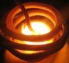
 Induction heater, vacuum tube oscillator.