If you need assistance, please send an email to forum at 4hv dot org. To ensure your email is not marked as spam, please include the phrase "4hv help" in the subject line. You can also find assistance via IRC, at irc.shadowworld.net, room #hvcomm.
Support 4hv.org!
Donate:
4hv.org is hosted on a dedicated server. Unfortunately, this server costs and we rely on the help of site members to keep 4hv.org running. Please consider donating. We will place your name on the thanks list and you'll be helping to keep 4hv.org alive and free for everyone. Members whose names appear in red bold have donated recently. Green bold denotes those who have recently donated to keep the server carbon neutral.
Special Thanks To:
Aaron Holmes
Aaron Wheeler
Adam Horden
Alan Scrimgeour
Andre
Andrew Haynes
Anonymous000
asabase
Austin Weil
barney
Barry
Bert Hickman
Bill Kukowski
Blitzorn
Brandon Paradelas
Bruce Bowling
BubeeMike
Byong Park
Cesiumsponge
Chris F.
Chris Hooper
Corey Worthington
Derek Woodroffe
Dalus
Dan Strother
Daniel Davis
Daniel Uhrenholt
datasheetarchive
Dave Billington
Dave Marshall
David F.
Dennis Rogers
drelectrix
Dr. John Gudenas
Dr. Spark
E.TexasTesla
eastvoltresearch
Eirik Taylor
Erik Dyakov
Erlend^SE
Finn Hammer
Firebug24k
GalliumMan
Gary Peterson
George Slade
GhostNull
Gordon Mcknight
Graham Armitage
Grant
GreySoul
Henry H
IamSmooth
In memory of Leo Powning
Jacob Cash
James Howells
James Pawson
Jeff Greenfield
Jeff Thomas
Jesse Frost
Jim Mitchell
jlr134
Joe Mastroianni
John Forcina
John Oberg
John Willcutt
Jon Newcomb
klugesmith
Leslie Wright
Lutz Hoffman
Mads Barnkob
Martin King
Mats Karlsson
Matt Gibson
Matthew Guidry
mbd
Michael D'Angelo
Mikkel
mileswaldron
mister_rf
Neil Foster
Nick de Smith
Nick Soroka
nicklenorp
Nik
Norman Stanley
Patrick Coleman
Paul Brodie
Paul Jordan
Paul Montgomery
Ped
Peter Krogen
Peter Terren
PhilGood
Richard Feldman
Robert Bush
Royce Bailey
Scott Fusare
Scott Newman
smiffy
Stella
Steven Busic
Steve Conner
Steve Jones
Steve Ward
Sulaiman
Thomas Coyle
Thomas A. Wallace
Thomas W
Timo
Torch
Ulf Jonsson
vasil
Vaxian
vladi mazzilli
wastehl
Weston
William Kim
William N.
William Stehl
Wesley Venis
The aforementioned have contributed financially to the continuing triumph of 4hv.org. They are deserving of my most heartfelt thanks.
Registered Member #1223
Joined: Thu Jan 10 2008, 04:32PM
Location:
Posts: 133
I just find schematic form RCA transmitting tube manual for induction heater using 833A. But i have a question: For me, 100nF seems to be way too high capacitance as they are usually in range of 1..10nF. Is there mistake or what? Schema: http://www.elisanet.fi/tonskulus/56ih.jpg
Registered Member #1223
Joined: Thu Jan 10 2008, 04:32PM
Location:
Posts: 133
Steve McConner wrote ...
The two 0.1uF's, C2, C5, are DC block capacitors, you size them so that their impedance is negligible at the working frequency.
The tank capacitor is C4.
Yes, I know C4 is tank and how hartley basically works. Anyway i have seen two different gridleak methods: cap and resistor in parallel and seriescap+resistor between G1 and cathode. As we know, in first method, both components are playing important role for biasing. Capacitor holds G1 negative while parallel resistor is for discharging that cap. Lower resistor value or smaller capacitor = less bias.
Second method, where resistor is between g1 and gnd, capacitor value is not important? It has nothing to do with actual biasing? I think it is not important capacitor at all, because there is allready dc blocking cap at plate side of tank circuit. So it is there just because of grid amp meter..?
Registered Member #30
Joined: Fri Feb 03 2006, 10:52AM
Location: Glasgow, Scotland
Posts: 6706
I don't think C5 is just there on account of the grid current meter. If it weren't there, the tank coil would short out the self-bias voltage, R and L2 would do nothing, and the tube would end up closer to Class-AB than C.
The time constant formed by R and C5 has to fall in a certain range to avoid squegging. You also have to avoid parasitic oscillations at the resonant frequency of L2,C5, and ditto for L1, C2.
All of these factors will have been taken into account by the original designer. Or maybe 0.1uF was the cheapest cap he could get with an 0.6A RMS current rating, back in the days before plastic film.
Registered Member #1223
Joined: Thu Jan 10 2008, 04:32PM
Location:
Posts: 133
Steve McConner wrote ...
I don't think C5 is just there on account of the grid current meter. If it weren't there, the tank coil would short out the self-bias voltage, R and L2 would do nothing, and the grid would get driven a lot harder.
Yes, indeed. But i wonder if the value of grid cap is critical..I think that much smaller value would still be acceptable. Like 10nF.
Registered Member #1223
Joined: Thu Jan 10 2008, 04:32PM
Location:
Posts: 133
Now i wonder where is tapping point for GND on tank coil. Any ideas? For class C operation, i think about 300V p-p gridvoltage is required. My tank coil will be made out of enameled 6mm2 copperwire so testing different tap points is not easy task. Somehow i need to know, maybe 2-3turn accuracy, tapping point. I can make few tap points for tankcoil. In schematic, tap point is near top of the coil but in practice that is not the case. It should be near grid end.
Registered Member #30
Joined: Fri Feb 03 2006, 10:52AM
Location: Glasgow, Scotland
Posts: 6706
I'd probably start by tapping it one-tenth of the way along. The tap point may well have been adjustable in the finished product.
You can use a separate feedback coil (made of thinner wire) instead of tapping the main coil, it makes no difference electrically. Either way, it's two coupled inductors connected together at a tap point.
Registered Member #1223
Joined: Thu Jan 10 2008, 04:32PM
Location:
Posts: 133
Yes, my current induction heater has separate grid coil. But hartley oscillator is more stable, feedback voltage is automatically controlled as persentage of tank voltage. And the construction itself is very simple.
If inductively coupled ticklercoil is used, it requires also separate primarycoil if matching transformer is used. So more space is wasted. This system should be as compact as possible. Thus, hartley circuit is used.
Ok, i will make some tapping points for each turn between turns 3 and 6 or so. There are 40turns total and tank voltage may be around 4kV. So, there should be 400Volts at 4th turn.. but we'll see how it works..:)
This site is powered by e107, which is released under the GNU GPL License. All work on this site, except where otherwise noted, is licensed under a Creative Commons Attribution-ShareAlike 2.5 License. By submitting any information to this site, you agree that anything submitted will be so licensed. Please read our Disclaimer and Policies page for information on your rights and responsibilities regarding this site.


 Induction heater, vacuum tube oscillator.
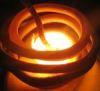

