If you need assistance, please send an email to forum at 4hv dot org. To ensure your email is not marked as spam, please include the phrase "4hv help" in the subject line. You can also find assistance via IRC, at irc.shadowworld.net, room #hvcomm.
Support 4hv.org!
Donate:
4hv.org is hosted on a dedicated server. Unfortunately, this server costs and we rely on the help of site members to keep 4hv.org running. Please consider donating. We will place your name on the thanks list and you'll be helping to keep 4hv.org alive and free for everyone. Members whose names appear in red bold have donated recently. Green bold denotes those who have recently donated to keep the server carbon neutral.
Special Thanks To:
Aaron Holmes
Aaron Wheeler
Adam Horden
Alan Scrimgeour
Andre
Andrew Haynes
Anonymous000
asabase
Austin Weil
barney
Barry
Bert Hickman
Bill Kukowski
Blitzorn
Brandon Paradelas
Bruce Bowling
BubeeMike
Byong Park
Cesiumsponge
Chris F.
Chris Hooper
Corey Worthington
Derek Woodroffe
Dalus
Dan Strother
Daniel Davis
Daniel Uhrenholt
datasheetarchive
Dave Billington
Dave Marshall
David F.
Dennis Rogers
drelectrix
Dr. John Gudenas
Dr. Spark
E.TexasTesla
eastvoltresearch
Eirik Taylor
Erik Dyakov
Erlend^SE
Finn Hammer
Firebug24k
GalliumMan
Gary Peterson
George Slade
GhostNull
Gordon Mcknight
Graham Armitage
Grant
GreySoul
Henry H
IamSmooth
In memory of Leo Powning
Jacob Cash
James Howells
James Pawson
Jeff Greenfield
Jeff Thomas
Jesse Frost
Jim Mitchell
jlr134
Joe Mastroianni
John Forcina
John Oberg
John Willcutt
Jon Newcomb
klugesmith
Leslie Wright
Lutz Hoffman
Mads Barnkob
Martin King
Mats Karlsson
Matt Gibson
Matthew Guidry
mbd
Michael D'Angelo
Mikkel
mileswaldron
mister_rf
Neil Foster
Nick de Smith
Nick Soroka
nicklenorp
Nik
Norman Stanley
Patrick Coleman
Paul Brodie
Paul Jordan
Paul Montgomery
Ped
Peter Krogen
Peter Terren
PhilGood
Richard Feldman
Robert Bush
Royce Bailey
Scott Fusare
Scott Newman
smiffy
Stella
Steven Busic
Steve Conner
Steve Jones
Steve Ward
Sulaiman
Thomas Coyle
Thomas A. Wallace
Thomas W
Timo
Torch
Ulf Jonsson
vasil
Vaxian
vladi mazzilli
wastehl
Weston
William Kim
William N.
William Stehl
Wesley Venis
The aforementioned have contributed financially to the continuing triumph of 4hv.org. They are deserving of my most heartfelt thanks.
Registered Member #89
Joined: Thu Feb 09 2006, 02:40PM
Location: Zadar, Croatia
Posts: 3145
Nice sparks considering what are you using...
Dago wrote ...
I dont think you are running in class-E. Your schematic is also very confusing because its hard to make out which crossing lines are connected and which ones are not.
Matt wrote ... PWM and Class-E don't mix...
And I'm worrying that with a very large breakout from the coil, the Q may suffer so much that maintaining class-E operation would be quite impossible... I'm also worrying that at such a low frequency, Class-E is pointless, and a halfbridge would be more rewarding.
Still a fantastic coil, and great pictures!
I don't think coil is running class E either - more in class-TVS with all the troubling power getting burned off as heat.
Mates, have you even tried to scope the C-E of the IGBT before calling the coil class E?
With true class E operation you won't need any TVS anywhere in the circuit.
That cap and diodes on collector are completely useless.
Also, how did you come to figure of 450W of your power consumption? Have you happened to measure cos fi of your system? It might be 450VA but it's terribly misleading to call it watts with huge amount of reactance at the input.
I guess I don't need to say that it would be enormously wiser to find an appropriate power supply for the coil rather than using insane amounts of motor caps as a reactive ballast.
And much safer for your circuit.
If you want to amke good progress go and use a bridge.
Good luck with audio-modulation too - last time I checked building a 400 watt audio amplifier of any type was not a trivial task.
Modulating the driver directly via open loop VCO or PLL might give you few cm of audio modulated sparks, but hard switching becomes really bad after that.
Make sure to use diodes on your bridge if you are going to do this.
Registered Member #1025
Joined: Sun Sept 23 2007, 07:53PM
Location: Czech Rep.
Posts: 566
Marko wrote ...
I don't think coil is running class E either - more in class-TVS with all the troubling power getting burned off as heat.
Mates, have you even tried to scope the C-E of the IGBT before calling the coil class E?
With true class E operation you won't need any TVS anywhere in the circuit.
That cap and diodes on collector are completely useless.
Also, how did you come to figure of 450W of your power consumption? Have you happened to measure cos fi of your system? It might be 450VA but it's terribly misleading to call it watts with huge amount of reactance at the input.
I guess I don't need to say that it would be enormously wiser to find an appropriate power supply for the coil rather than using insane amounts of motor caps as a reactive ballast.
And much safer for your circuit.
If you want to amke good progress go and use a bridge.
Good luck with audio-modulation too - last time I checked building a 400 watt audio amplifier of any type was not a trivial task.
Modulating the driver directly via open loop VCO or PLL might give you few cm of audio modulated sparks, but hard switching becomes really bad after that.
Make sure to use diodes on your bridge if you are going to do this.
I measured the power consumption via of the speed of rotating the disk on my flat power meter. I related it to speed of rotation when my 2KW boiling tea-kettle is running (I do not have AC Amp meter).
The bridge topology: I need two channels oscilloscope and probably different transistors for this. I was partially successful with the bridge but then suddenly both transistors died I do not know why. Considering seeing your problems – experienced power electronics users – I rather stick to my concept. More over I think I can beat any of the FET bridge SSTC I’ve seen until now (regarding the length of sparks)
Class E: Yeah you probably right. Most likely the coil is not Class E. I started to call it like that because the power part is similar to Steve’s Class E. However I have no idea what exactly the ClassE means – I just remember from the secondary school that is type of switching the transistor and I thought that the parallel resonance cap is the key. Thus small explanation would be great (I’m a biologist – sorry my ignorance)
The motor foil caps: I do not plan to substitute this caps (BTW: By what? 1KW transformer?). I personally think that they are the key for such a relatively good performance of the coil. They are discharged into the primary long time before the transistor is switched of (this I measured by oscilloscope). This means I can use the IGBT and do not need to care about the fall time. The transistor stays much cooler than it was in my bridge topology because of this.
TVS: The TVS heating is really not too much. I can run the coil for minutes and the TVS are just little warm (but the fan is on!). By increasing the coupling the TVS are cooler and cooler so hopefully I soon reach the stage that they are more or less spikes un-exposed.
Registered Member #580
Joined: Mon Mar 12 2007, 03:17PM
Location: Melbourne, Australia
Posts: 410
That is interesting. Ive never seen a series capacitor work for a single switch setup, but then again ive never tried placing it in parallel to the switching device. Soulds like it would work since it would discharge the capacitor before the next cycle although i think that would be canceling out the idea of LC resonant rise. Correct me if im wrong anyone?
I just tried a similar thing in a simulation and it sure seems to kill the resonance.
file>import $ 1 5.0E-6 10.391409633455755 50 5.0 50 l 304 160 304 208 0 1.0 -0.007635546547644788 c 304 208 304 256 0 1.0E-5 13.506643453460542 r 304 160 304 128 0 10.0 v 352 288 352 128 0 0 40.0 5.0 0.0 w 352 128 304 128 0 f 256 240 288 240 1 w 288 256 304 256 0 w 288 224 288 208 0 w 288 208 304 208 0 w 288 256 288 288 0 w 288 288 352 288 0 v 256 240 256 288 0 2 50.33 12.0 0.0 w 256 288 288 288 0 g 352 288 352 304 0 o 1 64 0 3 20.0 3.2 0
Registered Member #1025
Joined: Sun Sept 23 2007, 07:53PM
Location: Czech Rep.
Posts: 566
Avi wrote ...
so what is the capacitor there for even? to stretch out the 'flyback' pulse?
I'm not sure which cap you mean. The one which is in parallel to the diode - forgot about it that one is doing nothing.
On the other hand the 70nF/5KV which is in parallel to the transistor that one is really important. The coil works also without it but the efficiency is very poor and TVS gets really hot. My explanation is that it works mainly as an absorber of the spikes when the transistor gets open and because it is together with primary in resonance with the secondary the energy is used. It was actually quite difficult to tune the whole thing up - I was using 30V transformer for that trying different cap sizes and number of turns on the primary and measured the response on an incandescent tube (how strong it shines and what distance). But I can be completely wrong in my explanation...
Registered Member #1025
Joined: Sun Sept 23 2007, 07:53PM
Location: Czech Rep.
Posts: 566
Hi everybody, Today I increased the power to approx. 1500W, but unfortunately the increase in the length of the sparks is far from being linear to the energy investment. It looks I'll have to forget about 1m (40") sparks with this setting which was my aim .
When the fan is on, the transistor heat sink keeps RT after one minute run.(Actually there are two BUP314 in parallel). But, the TVS are getting hot, however I can keep the hand on them after the minute run (it means below 60 C).
Regarding your comments: I'm afraid of removing the protective diode (made from the bridge and parallel cap) from the circuit - are you guys sure it has no protective function? Ritchie Burnett also used diodes in his circuit which are in series with the FETs
Here is latest picture of sparks (18") and a short movie which was taken by my small digital camera...
Registered Member #1025
Joined: Sun Sept 23 2007, 07:53PM
Location: Czech Rep.
Posts: 566
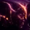
Not much progress this time - but I have to deal with flashes into primary. It is pretty annoying; because the coupling is so great in this position...I'll try to put more isolation around the secondary. I'm lucky that the set of transils can handle this
Here is the picture of my problem
and one picture taken just before the flashes started
Registered Member #795
Joined: Mon May 21 2007, 06:04PM
Location: Bocholt, Germany
Posts: 35
Good that your electronic is still alive ;)
Where did this spark come from? I can not see where it comes out of the secondary...
Perhaps your insulation is not that good? I have played with insulations between primary and secondary but my result was that the distance with air is nearly as good as the same distance between prim/sec made of plastic or something like that... At me it seemd that the sparks are just going through a lot materials without taking notice of the insulators.
I think less coupling is the only way that will prevent you for flashovers.
This site is powered by e107, which is released under the GNU GPL License. All work on this site, except where otherwise noted, is licensed under a Creative Commons Attribution-ShareAlike 2.5 License. By submitting any information to this site, you agree that anything submitted will be so licensed. Please read our Disclaimer and Policies page for information on your rights and responsibilities regarding this site.


 Ghetto I (450-2000W Class "TVS" SSTC)


 .
. 


