If you need assistance, please send an email to forum at 4hv dot org. To ensure your email is not marked as spam, please include the phrase "4hv help" in the subject line. You can also find assistance via IRC, at irc.shadowworld.net, room #hvcomm.
Support 4hv.org!
Donate:
4hv.org is hosted on a dedicated server. Unfortunately, this server costs and we rely on the help of site members to keep 4hv.org running. Please consider donating. We will place your name on the thanks list and you'll be helping to keep 4hv.org alive and free for everyone. Members whose names appear in red bold have donated recently. Green bold denotes those who have recently donated to keep the server carbon neutral.
Special Thanks To:
Aaron Holmes
Aaron Wheeler
Adam Horden
Alan Scrimgeour
Andre
Andrew Haynes
Anonymous000
asabase
Austin Weil
barney
Barry
Bert Hickman
Bill Kukowski
Blitzorn
Brandon Paradelas
Bruce Bowling
BubeeMike
Byong Park
Cesiumsponge
Chris F.
Chris Hooper
Corey Worthington
Derek Woodroffe
Dalus
Dan Strother
Daniel Davis
Daniel Uhrenholt
datasheetarchive
Dave Billington
Dave Marshall
David F.
Dennis Rogers
drelectrix
Dr. John Gudenas
Dr. Spark
E.TexasTesla
eastvoltresearch
Eirik Taylor
Erik Dyakov
Erlend^SE
Finn Hammer
Firebug24k
GalliumMan
Gary Peterson
George Slade
GhostNull
Gordon Mcknight
Graham Armitage
Grant
GreySoul
Henry H
IamSmooth
In memory of Leo Powning
Jacob Cash
James Howells
James Pawson
Jeff Greenfield
Jeff Thomas
Jesse Frost
Jim Mitchell
jlr134
Joe Mastroianni
John Forcina
John Oberg
John Willcutt
Jon Newcomb
klugesmith
Leslie Wright
Lutz Hoffman
Mads Barnkob
Martin King
Mats Karlsson
Matt Gibson
Matthew Guidry
mbd
Michael D'Angelo
Mikkel
mileswaldron
mister_rf
Neil Foster
Nick de Smith
Nick Soroka
nicklenorp
Nik
Norman Stanley
Patrick Coleman
Paul Brodie
Paul Jordan
Paul Montgomery
Ped
Peter Krogen
Peter Terren
PhilGood
Richard Feldman
Robert Bush
Royce Bailey
Scott Fusare
Scott Newman
smiffy
Stella
Steven Busic
Steve Conner
Steve Jones
Steve Ward
Sulaiman
Thomas Coyle
Thomas A. Wallace
Thomas W
Timo
Torch
Ulf Jonsson
vasil
Vaxian
vladi mazzilli
wastehl
Weston
William Kim
William N.
William Stehl
Wesley Venis
The aforementioned have contributed financially to the continuing triumph of 4hv.org. They are deserving of my most heartfelt thanks.
Registered Member #618
Joined: Sat Mar 31 2007, 04:15AM
Location: Us-Great Lakes
Posts: 628
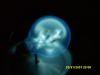
Well I was working on some stuff with the coil..and noticed that my positive wire was getting warm, so I disconnected all the gator wires, and connected the larger wire and now I've doubled the arc length, although now the heatsink for the fets gets hot fast. Got some pics and a vid.
Registered Member #240
Joined: Thu Feb 23 2006, 10:18AM
Location: Riga, Latvia
Posts: 1
Hi, I have decided to repeat Skory Mini Tesla Coil. It is a really wonderful design.I have used Mini Tesla Coil v.3 schematics from
I have put separate DC power supplies for controlelectronics (15V from 12V/1.1A transformer) and 32V from 24V/5A transformer) for Primaries (through R2 resistor and L1+L2 end).
My secondary is 75x200mm with 0.18mm wire. HV end of secondary is connected with 5x100mm bronze sharp-pointed rod (screw). (I have also tested 75x250x0.23 and 110x300x0.23 coils).
Primary (L1,L2) is 110mm diameter.
For TR1 I have used toroid 3E25 25x15x10mm with AL=5620() (12x24 turns of 1.1mm enamel wire).
This Tesla transformer is easy produce 8-10cm (about 4") sword-like streamers to air and 15-20cm arcs to ground (1hr working time is not a problem)
Oscilloscope measurements, pictures and movies will be published in a few days.
This coil is using only about 0.4-1.9A from 32V power supply depending of interrupter frequency
Registered Member #618
Joined: Sat Mar 31 2007, 04:15AM
Location: Us-Great Lakes
Posts: 628
I reaize that this topic is a bit dead but Incasesomeone was interested in doing this and was digging through the archives and found this topic, I figured I'd link a translated web page.
Registered Member #58243
Joined: Mon Jan 04 2016, 06:24PM
Location: Lithuania
Posts: 2
I saw nothing about reviving dead posts in the forum rules, so here it is: Few years ago I have studied the schematics of Skory ISSTC and a bit *improved it (*changed to my needs). Somehow I have lost the values of the components, but the schematic and video of operation is here . The most interesting thing is that it started working from 12V and was consuming only 100mA, so it is quite efficient. Later by increasing supply voltage the length of the sparks increased until it reached 20V, by further increasing the supply voltage output sparks remained the same, but current consumption increased drastically well above 7A if interrupter was set to 80% duty cycle. In the schematics I changed the snubber (R1, Z1, R8) to "softer" and simpler one, since the original one failed with smokes at 18V (because of low primary coil coupling), also added a pot to change duty cycle of interrupter and improvised better and cheaper power supply (voltage regulator) for 555 timer. If anyone still gets interest in this ISSTC design let me know, I can add more info about my variation and explain more about the original circuit and its operation if anyone needs it. Now I'm going to try to improve it further by making it more compact, increasing it's efficiency and lowering supply voltage even further. My goal is to make it run stable from 12V on constant (no interrupter) mode and staying under 2A with maximum possible output stremers, so that I could make it portable using 3 Li-Ion cells in series. Further I'm going to make a proper digital interrupter controlled via PC terminal program or using a dedicated MCU to enable it play music in MIDI files or from standard 3.5 mm audio jack. All my achievements and fails I'm going to post here if no one minds it.
Registered Member #58243
Joined: Mon Jan 04 2016, 06:24PM
Location: Lithuania
Posts: 2
Well, LiPos are better to handle more current, but I already have few LiIon batteries on hand and speaking about drill batteries – they are too big for what I'm going to make, since everything is going to be done using SMD parts. And the goal is to make it super stable and as efficient as possible, since last time it was good on 100mA, I see no need for massive batteries, but the sparks needs to be improved, while still using little power. Already ordered few super nice MOSFETs for my driver: They are awesome, imagine 1450A pulsed current, technologies are going far! I think should work perfect with a nice thick primary, good capacitor bank and a high current traces. Though a bit worried about input capacitance, it's freaking 12nF... But if I maintain resonant frequency low enough it would be still good, I hope... And also going to improve the MOSFET driving part for more current and faster switching, to cope with high gate capacity of the FETS.
Registered Member #4932
Joined: Thu May 17 2012, 01:42PM
Location:
Posts: 59
Could you use this schematic, but modify it a little bit so it uses an H-bridge of N-channel and P-channel mosfets which is driven directly by primary current feedback, which drives a single coil with a tank capacitor so you'll have like a drsstc variant of this circuit?
Registered Member #58332
Joined: Wed Jan 20 2016, 08:46AM
Location:
Posts: 1
Hello , also collected SSTC 2n2222 on the small size for the experiments , the circuit on the video . I noticed an interesting effect , which is found by chance during experiments with the coil . At presentation to the minus contact oscilloscope ( but not touching ) to the (+ ) power supply terminal SSTC, the latter will consume 10 times less consumption instead of 60 mA becomes 6mA . Video of the sstc Video effect described here
Registered Member #4932
Joined: Thu May 17 2012, 01:42PM
Location:
Posts: 59
I'm trying to create a drsstc version of this circuit. That's why here is a schematic I came up with to add zero current crossing detection to the interrupter without adding another transformer and with the ability to detect the zero crossing whether it's a falling edge or a rising edge. The circuit is drawn a little bit messily and the resistorvalues are chosen fairly arbitrarily.
V3 represents the secondary of the current transformer. V4 represents the signal generator part of the interrupter V(n014) is the waveform that's achieved when the clipped voltage of the current transformer is processed by an opamp. V(n010) is the output of my zero crossing detection circuit. V(n007) is the original interrupter signal V(n009) is the output interrupter signal, which is achieved by putting V(n010) on the enable input of a NAND D-Flipflop and V(n007) on the D input. I was wondering why it is that the output signal changes just a tiny bit before V(n010) goes high. Is this just an inaccuracy of LTSice or is something different happening?
I know a few other things about the circuit will have to change to create a DRSSTC like this, but it's got to be possible. OCD isn't gonna be in the (first itteration of) this circuit.
This site is powered by e107, which is released under the GNU GPL License. All work on this site, except where otherwise noted, is licensed under a Creative Commons Attribution-ShareAlike 2.5 License. By submitting any information to this site, you agree that anything submitted will be so licensed. Please read our Disclaimer and Policies page for information on your rights and responsibilities regarding this site.


 Interesting SSTC circuit