If you need assistance, please send an email to forum at 4hv dot org. To ensure your email is not marked as spam, please include the phrase "4hv help" in the subject line. You can also find assistance via IRC, at irc.shadowworld.net, room #hvcomm.
Support 4hv.org!
Donate:
4hv.org is hosted on a dedicated server. Unfortunately, this server costs and we rely on the help of site members to keep 4hv.org running. Please consider donating. We will place your name on the thanks list and you'll be helping to keep 4hv.org alive and free for everyone. Members whose names appear in red bold have donated recently. Green bold denotes those who have recently donated to keep the server carbon neutral.
Special Thanks To:
Aaron Holmes
Aaron Wheeler
Adam Horden
Alan Scrimgeour
Andre
Andrew Haynes
Anonymous000
asabase
Austin Weil
barney
Barry
Bert Hickman
Bill Kukowski
Blitzorn
Brandon Paradelas
Bruce Bowling
BubeeMike
Byong Park
Cesiumsponge
Chris F.
Chris Hooper
Corey Worthington
Derek Woodroffe
Dalus
Dan Strother
Daniel Davis
Daniel Uhrenholt
datasheetarchive
Dave Billington
Dave Marshall
David F.
Dennis Rogers
drelectrix
Dr. John Gudenas
Dr. Spark
E.TexasTesla
eastvoltresearch
Eirik Taylor
Erik Dyakov
Erlend^SE
Finn Hammer
Firebug24k
GalliumMan
Gary Peterson
George Slade
GhostNull
Gordon Mcknight
Graham Armitage
Grant
GreySoul
Henry H
IamSmooth
In memory of Leo Powning
Jacob Cash
James Howells
James Pawson
Jeff Greenfield
Jeff Thomas
Jesse Frost
Jim Mitchell
jlr134
Joe Mastroianni
John Forcina
John Oberg
John Willcutt
Jon Newcomb
klugesmith
Leslie Wright
Lutz Hoffman
Mads Barnkob
Martin King
Mats Karlsson
Matt Gibson
Matthew Guidry
mbd
Michael D'Angelo
Mikkel
mileswaldron
mister_rf
Neil Foster
Nick de Smith
Nick Soroka
nicklenorp
Nik
Norman Stanley
Patrick Coleman
Paul Brodie
Paul Jordan
Paul Montgomery
Ped
Peter Krogen
Peter Terren
PhilGood
Richard Feldman
Robert Bush
Royce Bailey
Scott Fusare
Scott Newman
smiffy
Stella
Steven Busic
Steve Conner
Steve Jones
Steve Ward
Sulaiman
Thomas Coyle
Thomas A. Wallace
Thomas W
Timo
Torch
Ulf Jonsson
vasil
Vaxian
vladi mazzilli
wastehl
Weston
William Kim
William N.
William Stehl
Wesley Venis
The aforementioned have contributed financially to the continuing triumph of 4hv.org. They are deserving of my most heartfelt thanks.
Registered Member #341
Joined: Thu Mar 23 2006, 07:41PM
Location: Northern Illinois, USA
Posts: 69
Thanks to the information that I obtained on this site and others, I have built my third coil. This is a 3.5†coil with a 5:1 form factor using 24 AWG wire. The primary is 11 turns of .25†copper tubing on .5†centers, tapped at ~10.5 turns. The top-load is a 3.75†by 17.75†toroid. The gap is a blown static gap (like a sucker gap, but with positive pressure) set at .20â€. The MMC is 10 (5 in series on each side of the primary) .15 uF CD 942's with the whole thing powered by a 60mA/15kV Franceformer NST protected by a Terry filter (thanks Terry.)
There is no more than about 4' of wire to connect all of the components, 12 ga. solid copper from NST to Terry filter to spark-gap and 10 ga. stranded between caps, gap, and primary.
The problem that I'm having concerns the caps and the bleeder resistors. To make repairs easy I mounted the caps with brass screws on strips of poly cutting board. To keep leads short the caps were mounted end to end so there is only about .5†of lead between caps. The problem is trying to keep the bleeder resistor leads short while reaching around the cap. I allowed 5/16†between the cap and the resistor and have found that this is not enough as I have had 4 arc overs.
My questions:
1. What is the minimum safe distance between cap and bleeder or would it be best to just mount the bleeders on the other side of the poly for the minimum amount of connecting wire.
2. Is there a minimum distance that the MMC should be from the primary coil due to the magnetic field? Does it matter if the cap bank is parallel or perpendicular to the primary?
3. Is there any advantage to mounting the gap close to the primary coil in an effort to get the magnetic field to help quench the gap?
Registered Member #127
Joined: Fri Feb 10 2006, 03:36PM
Location: Cincinnati, OH - USA
Posts: 44
1) I like to keep my bleeder resistors airborne entirely and mount them on the opposite side of the board to which I strap the caps. That gives them plenty of space to heat up and not melt anything and keeps a nice insulator between them and the caps. In normal operation they really shouldn't heat much anyway, but I still like to give them room to breathe. From my experience 1/4 inch seems to be just fine. I don't worry about the bleeder resistor lead lengths since they don't really do much when the coil is operating (in the way of providing power). I don't think their inductance (I assume that is why you want to keep them short) even matters (one of the more experienced guys here might be able to verify/correct this notion).
2) My 900 watt coil had the MMC right below the primary (about 8" under. I never noticed any difference in performance (and nothing blew up due to transients). Originally it was about 16" away, but I moved it when I added a 2nd NST to the setup. And I was even using the less durable CD 940Cs.
3) Interesting concept. I never thought of it, but my initial guess would be no. I would think the magnetic field might push the arc around a bit, but not help it quench. But if your setup can be readily changed around try it and post the results.
Registered Member #135
Joined: Sat Feb 11 2006, 12:06AM
Location: Anywhere is fine
Posts: 1735
My capacitor bank ( 40KV TDK caps) was mounted on two sheets of circuit board and etched so that there was an island of copper on both sides, and then the caps mounted to it to form the bank. I didn't notice any performance difference between it standing upright and lying on its side with the system, other then one important factor, the leads to the bank. Keeping the leads short and heavy is really important for performance.
There is one major issue I had with mounting the cap bank under the flat primary though, and some issues with the cap arrangement. The problem is that if you don't coat the copper, it tends to arc over, even with a 1" margin on either side. I had flashovers from plate to plate, and flashovers from my primary to plate. The major cause of the primary flashovers was due to a simple factor, how I mounted my primary. The primary coil was held down by little plastic wire tie holders that were screwed into the wood coil support, so the arc started from the tip of the screw to the plate, about 3" distance. Once I put Corona Dope on the plates, the arcovers ceased.
I think in SGTC keeping everything short and close together is partly important, but when you get to about 3" separation you see some pretty nasty arcovers, so you could increase the distance or use insulating coatings, teflon sleeve, the usual stuff.
There are some pictures of my setup around here and on the old forum too, I can't really find anything at the moment, I have too many files spread out.
Registered Member #160
Joined: Mon Feb 13 2006, 02:07AM
Location: Melbourne, Australia
Posts: 938
Mounting the primary with metal screws is just asking for an inefficient coil and perhaps other problems like arcing over. There are many ways of mounting the components without using screws, it just takes some imagination. 1. Mine is mounted one on each side of versa strip board. Had to dremel of some of the copper strips to make it arc safe, but no problems. 2. Concerning the arc over, I just measured the 15kV 60mA no load spark and doubled it. this should be a safe minimum distance for all components excluding secondary. I did have one arc over on my system because one of the bleeders had some of the enamel scratched off on it, so it arced and burnt it out. 3. I highly doubt that the magnetic field would be anywhere near strong enough to quench a spark gap.
Registered Member #135
Joined: Sat Feb 11 2006, 12:06AM
Location: Anywhere is fine
Posts: 1735
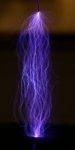
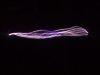
For one, the primary was mounted on little plastic wire tie hold downs, and two, metal screws has little effect on efficiency, and if you need some proof, its right here:
Registered Member #135
Joined: Sat Feb 11 2006, 12:06AM
Location: Anywhere is fine
Posts: 1735
Sure, whatever you say. You worry about the screws, I'll worry about the poor coupling, which has an impact of several orders of magnitude greater then the hardware.
Registered Member #341
Joined: Thu Mar 23 2006, 07:41PM
Location: Northern Illinois, USA
Posts: 69
Thank you all for your responses. Please forgive my tardiness in responding, an unexpected illness and then death in the family several states away required my presence, so I have been computer/internet deprived.
Tetrafluoroethane, you are correct that my intent is to minimize the amount of wire in the primary and optimize the placement of components in an effort to limit stray inductance. I have now done as you suggested and mounted the resistors on the other side of the poly from the caps.
Had another cap and resistor fail last night, but it may have had a manufacturing defect beings as it failed immediately on power-up. Still, I'm beginning to think that I'm going to have to use two strings of 20 caps rather than one string of 10 if I'm going to reduce the number of failures. It still seems odd that I have had 4 failures on one side of the primary coil and only one on the other.
Hazmatt, I think that I'm going to bolt the MMC bank directly to the sparkgap, then the only wire in the primary circuit will be between the caps and the resistors in the MMC, and the MMC and the primary coil (remember that I have half of my caps wired to either side of the primary so both banks will be bolted to either side of the gap as well.)
Goldsphere, as noted above I'm now mounting my bleeders on the opposite side of the poly from the caps. I have no way of knowing how well my gap quenches. I believe that it quenches relatively well only because I get decent arcs and have very, very little erosion of the copper contacts. The magnetic quenching question was kind of mental masturbation (just can't pass up the possibility of something for nothing). I agree that there is probably little chance of enhanced quenching, but every little bit helps and I just want to be sure.
Registered Member #160
Joined: Mon Feb 13 2006, 02:07AM
Location: Melbourne, Australia
Posts: 938
ArcLight wrote ...
(remember that I have half of my caps wired to either side of the primary so both banks will be bolted to either side of the gap as well.)
Is there a certain reason why you have decided to do this? rather than have one bank? It seems to me that the two banks would have to be well balanced. This might be the cause of the failure on one side of the primary. Maybe someone else can shed more light on this?
Registered Member #341
Joined: Thu Mar 23 2006, 07:41PM
Location: Northern Illinois, USA
Posts: 69
Goldsphere,
The short answer is I believe that Tesla did it that way.
The longer answer is that at first I didn't think that it would make any difference how the tank cap was integrated into the primary circuit of a Tesla coil. But, after reading some papers about Tesla's “equi-drive†and magnifiers I decided that I would divide the caps between the opposite ends of the primary coil and spark-gap.
While still using MOTs and salt water caps with the gap parallel to NST. Gap, caps, and primary is series, not equi-drive. I found that the side of the gap without caps got much warmer than the side with caps (about room temperature on one side and guessing about 300 F. on the other.)
After changing the MOTs to a 15Kv/60Ma NST and splitting the caps (now MMCs) evenly I still have some slight uneven warming of the gap, but it's much better than before. I think that with uneven splitting of the caps, I may be able to spread the load more evenly across the primary and get longer life for all components.
This site is powered by e107, which is released under the GNU GPL License. All work on this site, except where otherwise noted, is licensed under a Creative Commons Attribution-ShareAlike 2.5 License. By submitting any information to this site, you agree that anything submitted will be so licensed. Please read our Disclaimer and Policies page for information on your rights and responsibilities regarding this site.


 SGTC Component Spacing Questions